COTS and Design Pattern Based High Fidelity
Flight Simulator Prototype System
Shupeng Zheng
School of Mechatronics Engineering, Harbin Institute of Technology, Harbin, China Email: [email protected]
Shutao Zheng and Junwei Han
School of Mechatronics Engineering, Harbin Institute of Technology, Harbin, China Email: {zhengst, hjw}@hit.edu.cn
Abstract—Flight simulator is among the most sophisticated software systems in existence. It is highly distributed, has rigorous timing requirements, and must be amenable to frequent updates to maintain high fidelity with the ever-changing vehicle and environment it is simulating. Current flight simulation framework and software developing pattern are complicated to use and time consuming. We have accomplished a flight simulator prototype system based on a new distributed real-time simulation framework and non-flight-certified Commercial-off-the-shelf (COTS) solutions and have proved its fidelity and coordination characters as a flight training device. The distributed real-time simulation framework uses mediator design pattern as an information “broker” among flight simulation models of a sub-system which minimizes model interdependencies, improves the extendibility for the simulator and makes the maintenance easier. Meanwhile, the simulation models and executable code in the simulator were generated through COTS software and run on a PC cluster by which the difficulties of programming tasks are descend. The simulation modeling process and virtual prototype of the motion system are also expatiated. The validation methods and contrasting simulation results are presented finally to show the feasible design to carry out flight simulation with high quality.
Index Terms—COTS, design pattern, flight simulation, real-time system, fidelity, prototype system
I. INTRODUCTION
The aim of flight simulation is to produce and control animated images, sound reproduction, and device feedback in a manner as realistic and responsive as the real flight, and chasing this ideal has constantly pushed the flight simulator study forward in many different ways. Individual simulators have adopted techniques such as multi-processor, high performance graphics cards, distributed sensors and actuators to approach the desired objective. In comparison with the flourish of hardware
power, there is large lag disparity of the development in the software system. The main reason for the phenomenon is result from the high complexity of the flight simulator software system. For example, a typical level D full mission flight simulator is commonly comprised of over a million lines of code which must run and communicate under the constraint of hard real-time performance [1].
Commercial simulation development software and software design patterns [2] are effective, efficient, and established solutions to common software design problems in the flight simulation. Represented by
MATLA○R/Simulink, MATRIXx/System Build, etc., the
commercial simulation development software are now widely used in engineering simulation. They have become the modeling tools of choice because their
graphic interfaces mimic the function-block
methodologies taught in universities and technical schools. This reduces the learning time and increases engineering productivity. Another useful feature of these packages is automatic code generation which frees engineers from the tedious and error-prone task of writing code. They make it possible to go from concept to simulation without ever having to write code. And by using “tried and true” software design patterns, the enhanced extendibility and easier maintenance for the simulation software system can be efficiently achieved.
Considering advantages of developing simulation application based on COTS solutions and software design patterns, we built a Boeing 737-800 flight simulator prototype system. The models and executable code in the simulator were generated through commercial simulation
development software and run on a PC cluster,which
composed a man-in-the-loop real-time distributed flight simulation system. And through using the mediator design pattern, a distributed real-time simulation framework is proposed which simplifies model interfaces and eliminates model interdependencies. By this means, the difficulties of programming tasks descend while the quality of the simulator is still excellent. This system afforded a platform for key technology research of flight simulator such as flight dynamic modeling methods,
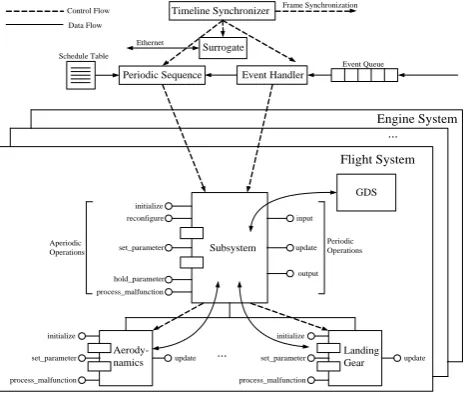
Figure 1. A generic flight simulation functional model
Periodic Sequence
initialize reconfigure
set_parameter
hold_parameter process_malfunction
input
update
output Aperiodic
Operations
Periodic Operations
update set_parameter
initialize
process_malfunction
Subsystem
...
Aerody-namics set_parameter update
initialize
process_malfunction
Landing Gear
GDS Event Handler
Schedule Table
Event Queue
Flight System Engine System
...
Control Flow Data Flow
Surrogate
Frame Synchronization
Timeline Synchronizer
Ethernet
Figure 2. Structural elements of the distributed real-time simulation famework.
advanced simulation methods, man-machine-interface, and so on. This paper describes our work and shows the character of flight simulator. In section two, a functional model of a flight simulator is presented. Section three introduces the distributed real-time simulation framework based on the mediator design pattern. In section four, we choose a main route of data flow in the flight simulator and describe the building methods of simulation models along the route. This is presented to show the advantage
of rapid modeling method provided by MATLAB○R and
the reason why we accomplish the software development easily while with high quality. In section five, we present a method to testify the coordination of our flight simulator. And then we give the simulation results which are compared with true airplane flight test record to verify the fidelity of the flight simulator. Finally we conclude our work and indicate its effectiveness.
II. GENERIC FLIGHT SIMULATION FUNCTION MODEL
Before discussing the structure and properties of flight simulator software framework any further, it is useful to look at the functionality which a flight simulator-any flight simulator must support. The functional model [3] of flight simulator is shown in Fig. 1.
A flight simulator must provide a great number and great variety of services to its users. Its users consist of the crew being trained: pilot, co-pilot, and instructor-operator. The instructor-operator is in charge of the pedagogical aspects of flight simulation—it is the person who decides what mission will be run, and under what conditions, hence the name “instructor”. However, this person also controls the simulation in real time, hence the name “operator”.
The flight simulator software must provide visual, audio and motion cues to the users—the aircrew. In addition, it has to provide force-feedback cues. These sensory cues are generated in order to provide the sights, sounds and feel of a normal air vehicle. The software must also simulate the air vehicle’s normal set of instruments. These must all be simulated to a high degree of fidelity, with a high degree of coordination.
It is important to keep this set of functions in mind, because the satisfaction of all aspects of this functionality, both in terms of the array of functions and their real-time performance, is the requirements which a flight simulator must fulfill.
III. THE DISTRIBUTED REAL-TIME FLIGHT SIMULATION
FRAMEWORK
Before the advent of object-orient simulation technology and design patterns, the data-driven software architecture was the de facto standard for aircrew trainer simulation software. Dating back to the earliest digital computer based aircrew trainers, data-driven software architectures provided a good solution to the trainer simulation software problem as it existed from the 1960s to the 1980s [4]. It was an effective solution to the trainer software problem as it existed 20 years ago; the problem, however, has changed dramatically. Today’s airplanes are more complex and dynamic; today’s computer hardware is less expensive and more powerful, while today’s software is more complex and expensive. Application of the data-driven architecture to software trainers for modern aircraft is something of a mismatch between the newer problem and the older solution.
Symptoms of this mismatch surface during
maintenance of systems based on the data-driven architecture. The functional decomposition of the data-driven architecture spreads the state information and calculations, as well as the communication of state information, across the subsystems. Data coherence problems have resulted from this spreading. The spreading of state representation, calculation, and communication leads to interdependencies among the
data-driven architecture’s system routines. Those
interdependencies complicate the concurrent
development of the simulator software, the incremental development of the simulator software, simulation of malfunctions, and freezing, saving, and restoring of state information.
Synchronization Periodic Operations
Aperiodic Operations
Slack Time
Time t(n) t(n+1)
Periodic Communication
Figure 3. Time allocation.
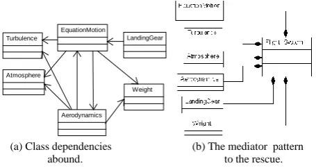
Aerodynamics EquationMotion
Weight Turbulence LandingGear
Atmosphere
(a) Class dependencies (b) The mediator pattern abound. to the rescue.
Figure 4. Comparison of components’ coupling.
FlightSimulator system_list:list<Subsystem*> update():void
Boeing_737_800
update():void
Flight
Subsystem flight:Flight_Simulator* getFlight():int update():void
Flight_System
update():void
Mediator: Decouple the model from the flight
SimulationModel mode:Mode& timer:Timer& getMode():int getTimer():int initialize():int
Aerodynamics
Model
Figure 5. The flight system mediator.
The executive handles coordination issues: real-time scheduling of sub-systems, synchronization between processors, event management from the instructor-operator station, data sharing, and data integrity. These functions are implemented via “Timeline Synchronizer”, “Periodic Sequencer”, “Event Handler”, and “Surrogate”. The application handles computation, which solely consists of modeling the air vehicle. The application’s functions are implemented by “Subsystem” and “model”.
A. The Executives
The flight simulator is typically implemented as multiple processes on multiple, distributed processors. The executive binds the group of sub-systems within a given process, handling the scheduling of those
sub-systems. The executive(s) are responsible for
coordination of the multiple processes within the flight implementation, external (to a system) communication of state information, and the overall synchronization of a system with the rest of the simulator.
The executive is partitioned by function, into software that supports periodic control, aperiodic control, external communication, and overall control and coordination. Periodic control is handled by the “Periodic Sequencer”. It invokes the sub-system according to a previously computed, fixed scheduling table, thereby ordering the execution of its associated sub-systems. Aperiodic control is handled by the “Event Handler”, which is responsible
for determining and then executing the appropriate code in response to an event (e.g., a request from the IOS). External periodic communication is handled by the “Surrogate”, which is responsible for hiding the details of external state information communications. The overall system is controlled by the “Timeline Synchronizer”, which is responsible for synchronizing the system with the rest of the simulator, and scheduling and invoking the periodic and aperiodic control software. The basic schedule scheme is based on the fixed period of time allocation, as shown in Fig. 3. The concrete scheduling algorithms are detailed described in [5, 6].
B. The Mediator Based Sub-system Architecture
Besides the executive, Fig. 2 also shows the module types that exit in the application sub-part. There are only two: the “Subsystem” and the “Simulation Model”. We used the mediator design pattern to decouple simulation models inside and outside the sub-system. It is a kind of “restrict communication” tactic. In the pattern, “Subsystem” passes data to and from other subsystem instances and to their simulation models. Subsystem simulation models pass data only to and from their father, namely “Subsystem”, not to any other sub-system simulation models. They also receive control only from their father and return it only to their father. These
restrictions on data and control passing preclude a sub-system simulation models from passing data or control even to a sibling.
Fig. 4 (a) is the class diagram for the models of flight system. The figure illustrates the interdependencies that result when simulation models of a flight system share data through direct interaction. Each class is dependent on all the other classes from which it needs data. This creates a tightly coupled system. Any new data or behavior added to one class affects all the other classes that depend on it. As the tightly coupled system grows, it tends to take on the characteristics of a monolithic class. This limits reusability, hampers testability and significantly increases the software maintenance cost. In the worst scenario, every class would be dependent on every other class. After use of the mediator design pattern, their explicit dependencies are eliminated. Fig. 4 (b) illustrates the impact of a mediator on the system shown in Fig. 4 (a). It is the superior design. Fig. 5 shows how a mediator class fits into the framework to decouple one part of a design from another.
Figure 6. Models of the flight sub-system.
IV. MODEL CONSTRUCTION
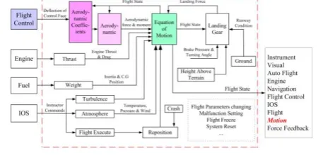
As seen in Fig. 2, flight simulator contains many sub-systems, and every sub-system contains tremendous simulation models. Just aircraft model which belongs to simulation model is composed of flight control sub-system, engine sub-sub-system, navigation sub-sub-system, auto flight system, fuel system, electrical power sub-system, hydraulic power sub-sub-system, air conditioning sub-system, and so on. Further more, flight sub-system contains aerodynamic model, equation of motion, atmosphere model, crash model, ground model, height above terrain, reposition, thrust model, weight model, and so on. Model and model connect each other by data flows, which organize a complex big net. But tremendous data flows have a basic and main route, which begins from data input by pilots, and passes flight control sub-system, flight sub-system, finally outputs flight state to visual sub-system, instruments sub-system, motion sub-system and force feedback sub-system. For the sake of convenience to show the rapid prototype modeling method and prepare for the next section to testify the coordination and fidelity of our flight simulator, we choose some models on this typical route to describe their building process, such as equation of motion, aerodynamic coefficients, and the virtual prototype of the motion system, which are colored in Fig.6.
Fig.6 describes the models of the flight sub-system which are enclosed in dash frame. The most important block is the equation of motion. It works out the flight state according to the summation of forces and moments acting on the center of gravity of the simulated aircraft (A/C). The forces and moments come from various source. Firstly, aerodynamic coefficients are defined in the Aerodynamic Coefficients block as functions of the flight state of the A/C including such as Mach number, angle of attack, angle of sideslip, true airspeed, and geometric characteristics of the aircraft. The geometric characteristics of the aircraft include such as control surfaces deflections, high lift devices, landing gear, and center of gravity location [7]. And then, aerodynamic block uses these coefficients, air density, true airspeed, wing platform area, wing span, and wing mean aerodynamic chord to work out aerodynamic forces and moments. Secondly, the landing gear block works out landing forces and moments according to flight state and runway conditions. Thirdly, the Thrust block works out engine thrust, engine drag and ram drag. Finally, the gravity, of course, is computed in the weight block. The
weight block also calculates the inertia of tensor and estimates the center of gravity according to the fuel consumption, landing gear position, and deflections of the wing flaps. The equation of motion summates these forces and moments, then integrates the effect of wind and turbulence, furthermore obeys the commands sent out by IOS and at last outputs the state of flight. The detailed descriptions of some models building methods are following.
A. Equation of Motion
As the core of the simulation model, the equation of motion affects the fidelity of the flight simulation directly. So we consider many effects which influence the dynamic of the A/C, such as earth rotation, earth flattening, mass of A/C altering. And we use quaternion instead of Euler angles to describe the A/C attitude in order to avoid singularity. Meanwhile, we neglect the earth’s nutation and polar motion which affect the flight dynamic trivially.
The Equation of Motion block considers the rotation of an Earth-centered Earth-fixed (ECEF) coordinate frame
XECEF,YECEF,ZECEF
about an Earth-centered inertial(ECI) reference frame
XECI,YECI,ZECI
. The origin of theECEF coordinate frame is the center of the Earth, additionally the body of A/C is assumed to be rigid, an assumption that eliminates the need to consider the forces acting between individual elements of mass. The representation of the rotation of ECEF frame from ECI frame is simplified to consider only the constant rotation
of the ellipsoid Earth (e) including an initial celestial
longitude (LG(0)) [8].
The translational motion of the ECEF coordinate frame
is given in (1), where the applied forces [Fx Fy Fz]T
are in the body frame.
[ ] ( b bi( e i))
T z y x
b F F F mV DCM x
F
m(VbbVb2(DCMbieVb)
DCMbi(
e(
exi))). (1)Where DCMbiis the direction cosine matrix from ECI
frame to Body frame, and the change of position in ECI
(xi) which is used to define the A/C position in ECI (xi)
is calculated in
T ib b e i
ECI ECI ECI
i x y z DCM V x
x [ ] . (2)
The velocity in body-axis Vb is defined as [u v w]T,
angular rates in body-axis b as [p q r]T, and Earth
rotation rate e as T
e]
0 0
[ . The relative angular
rate (rel) used to calculate the attitude of A/C in
body-axisisdefined as
rel
bDCMbi
e, (3)The rotational dynamics of the body defined in body-fixed frame are given in (4), where the applied
moments are [L M N]T , and the inertia tensor
Iis with respect to the body origin.
[ ] b b ( b)
T
b L M N I I
12 Ab 11 pdot,qdot,rdot 10 p,q,r 9 p,q,r rel 8 Vb 7 DCM_ef 6 DCM_be 5 DCM 4 Euler 3 XG 2 XECEF 1 VECEF 1 s xo p,q,r pm_0 [0 0 w_E]
m/s m/s Velocity Conversion Matrix Multiply Matrix Multiply uT LG0 LG0 Trigger [Vb] [DCM_IF] [XEI] [XECEF] [Trigger] [Trigger] [DCM_IF] [DCM_IF] [Trigger] [Vb] [XEI] [Trigger] [XECEF] LG DCM_IF ECEF to Inertial Xf
l h ECEF Position to LLA Vb f orces mass mdot I I_dot f orces mass I, I_dot Out9 Determine Force,
Mass & Inertia
LG(0) LG Celestial Longitude
of Greenwich p q r I, I_dot Moments
pdot qdot rdot
Calculate omega_dot XEI Ab p q r DCM we Trigger
Vb
p q r rel Calculate Velocity
in Body Axes Vb DCM_if we DCM Trigger V_mass XEI Calculate Position in EI
p q r mu l DCM_if Trigger DCM Euler DCM_be DCM_ef Calculate DCM & Euler Angles DCM_be DCM_ef DCM_f b Calculate Body to ECEF deg rad Enable 7 Triger 6 I 5 I_dot 4 mass 3 m_dot 2 Moments 1 Forces
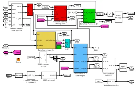
Figure 7. Simulink diagram of the equation of motion.
Calculate Position in EI
2 XEI 1 V_mass A B C Cross Product C = AxB pxwe 1 s xo p xg_0 Matrix Multiply Matrix Multiply Matrix Multiply uT
l h
Xf
LLA to ECEF Position 4 DCM 5 Trigger 4 DCM 3 we 2 DCM_if 1 Vb
Figure 8. Simulink diagram of A/C reposition and position calculating.
The integration of the rate of change of the quaternion vector is given below,
3 2 1 0 3 2 1 0 0 0 0 0 2 1 q q q q p q r p r q q r p r q p q q q q
. (5)
Now, we have listed the equations which satisfy one of the functions of the Equation of Motion block. The next step, we need to transform these equations to Simulink models. Fortunately, Aerospace Blockset [9] which is one of the Simulink components offered us a ready-made model, Custom Variable Mass 6DoF ECEF (Quaternion). So we just needed to do a little improvement on it. This is an advantage of COTS software, mature, reliable and easy to use. Fig.7 presents the position of each equation. Equation (1) were realized in the blocks identified by red, (2) in the green, (4) in the yellow, (3) and (5) in the light blue.
There are other functions need to be realized in the Equation of Motion block, which don’t compute the state of the A/C. These functions allow IOS to freeze the A/C, or reset the state of the A/C, such as reposition. For freezing the A/C, we add an Enable block colored by orange in Fig.7 to hold the integrators in the Equation of Motion. For reposition, we used an external signal, which was colored by magenta in Fig.7, sent by IOS to reset the integrator in Fig.8. Once the falling edge trigger signal is coming, the integrator will be reset to its initial condition value colored by green in Fig.6 which has been modified by IOS using the API function provided by RT-Lab. And then the position of A/C will be reset to the new value. Fig.8 describes the Simulink diagram of equations to
calculate A/C position in ECI coordinate frame, and the A/C reposition function.
B. Aerodynamic Coefficients
The reason why an aircraft can fly is the aerodynamic force acting on it and lifting it up. The Aerodynamic Coefficients block reflects the flight character of the A/C. Accurate identification of aerodynamic models of aircraft behaviour is important to the fidelity of a flight simulator. Here, we use cubic spline to represent nonlinear aerodynamic functions. This method offer advantages over traditional linear lookup table representation for the problem of parameter identification from flight test data. The method offers a natural fit to a smooth function with a twice continuity property. In addition, the cubic spline
coefficients offer improved conditioning to the
identification process, promising improved convergence properties of identification algorithms [10].
A spline is a smooth piecewise polynomial function. There are two commonly used ways to represent a polynomial spline, the ppform and the B-form. A spline in ppform is often referred to as a piecewise polynomial.
The ppform of a polynomial spline of order kprovides a
description in terms of its breaks
1…
l1and the localpolynomial coefficients cjiof its lpieces as in (6),
, ) ( ) ( 1
k i ji i k jj x x c
p j1:l. (6)
A cubic spline is of order 4, corresponding to the fact that it requires four coefficients to specify a cubic polynomial. The ppform is convenient for the evaluation and uses of a spline.
The concept of the ppform extends naturally to functions with more than one independent variable. Such a bivariate spline comprises, analogously, a cell array of break sequences, a multidimensional coefficient array, a vector of number pieces, and a vector of polynomial
orders. We made use of MATLAB○R Spline Toolbox [11]
to achieve the spline functions. Fig.9 shows a graph of an extract of the basic lift coefficient due to flap and body angle of attack taken from Boeing aerodynamic data package (Boeing D611A001 Revision G). This is similar to a conventional lift curve, the coefficient increasing with the angle of attack and the effective flap deflection angle. The spline function as in (7) has coefficients which
form a 121224matrix, breaks which form a 12cell
with 54 values of angle of attack, 7 values of effective flap deflection, and 53 pieces in column and 6 pieces in row.
) ,
( f
bf f
Cl . (7)
The piecewise polynomial functions which represent the aerodynamic model are recorded in a file after they were identified. Once the simulation task beginning, the file is loaded to memory and used by real-time simulation program to computer the aerodynamic coefficients according to the parameters of the spline functions.
Everything in this process from the spline construction
to their use becomes easy with the help of MATLAB○R.
Figure 9. Spline of basic lift coefficient due to flap and angle of attack.
ADAMS Sub-assemblies (Parts need to be driven)
ADAMS Complete Assembly
VRML VRML Files
Matlab simulink SimMechanics Model
Matlab simulink Simulation Model VRML
VRML Model
LabView Virtual Reality
QNX Real-time model assemble
Save as VRML CAE
Compose as transform
nodes and add Java script Add controllerand interface
Activex
Cortona Contact API RT-Lab
UDP
Figure 10. The development process of the motion system’s virtual prototype.
Figure 11. Structure of the computer cluster.
C. Virtual Prototype of the Motion System
As we know, it is difficult to analyze kinematics and dynamics of Stewart platform. If we designed and developed the virtual prototype of the platform with traditional method, it would cost a lot of time on dynamic equations [12]. Even if we worked out the dynamic equation of every part of the Stewart platform such as actuators, joints, and the platform, it was also difficult to drive these numerous parts in virtual reality by those equations. For these reason, we chose SimMechanics CAE Translator as a bridge to combine CAE of the Stewart platform’s mechanical system, SimMechanics
model and virtual reality. With the CAE Translator,
models of the motion system’s virtual prototype were
unified in the MATLAB○R environment and could be used
to drive virtual reality.
This method used SimMechanics CAE Translator to transform ADAMS geometric assembly into Simulink block diagram model. After adding controller’s model, actuators’ models and washout filters, the motion system’s model could perform dynamics simulation. Then the model was combined with the flight simulation model as a whole. Finally we used RT-Lab to compile the whole model and loaded it to separate computational nodes, which was the source of driving signals to virtual reality.
At the same time, we built a LabVIEW Virtual Instrument (VI) to contain the VRML model which was generated from ADAMS sub geometric assemblies and added Java script node. Then UDP communication blocks were added to receive driving data and sent back object-to-object collision information which was provided by Cortona Clients (ParallelGraphics. Inc) and would be used for platform structure interference validation. Connecting the simulation part with the virtual reality part by Ethernet was the last step to complete the virtual prototype of the motion system. The development process is described in Fig.10.
The virtual prototype has the same control interface and similar dynamic character as the real motion system.
And its animation is exquisite as in Fig.2. Its major advantage is utilizing the existence resource in the process of motion platform design stage. The method decreases the difficulties of generating virtual prototype and makes the development fast and high quality.
V. COORDINATION AND FIDELITY VALIDATION
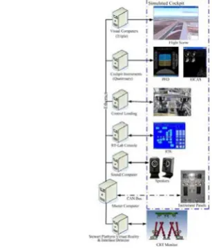
An experimental flight simulator has been built for testifying the software framework. The whole system consists of 11 PCs as a cluster, control loading system, digital geometry and soft edge correction machine (Equipe 3ch-ProMap), 3 projectors (Equipe Contour 300), 2 speakers, and a virtual prototype of motion system. The refresh rate of the flight simulation model was set to 30 frames per second, which could ensure fidelity and coordination of the simulator.
Simulation models were transformed to C code
through MATLAB○R/RTW and loaded by RT-Lab to
0 5 10 15 20 25 30 35 40 45 50 -50
0 50 100
Time (sec)
A
lti
tu
de
(
m
)
A/C Altitude
0 5 10 15 20 25 30 35 40 45 50
-10 -5 0 5
Time (sec)
A
ng
le
(
de
g)
Elevator Angle Flight Test
Simulator
Simulator
Figure 14. Elevator angle vs. A/C altitude during taking off
Flight Control IOS
Aerodynamic Coefficients
Equation of Motion
1 S
1 S
1 S
1 S Pilots
Visual System
Cockpit Instruments
Motion System Force-Feedback
System
Task Executive
Process
Flight State
Flight State
Flight State Feedback Begin
End
Once the states equal, or a flag appears, record the output
value of the Integrator corresponding to the cue system with task done
1 time1
time2
time3
time4 1
1
1
A. Coordination Validation
The cues which a flight simulator provides to the pilots being trained must be strictly coordinated. It wouldn’t do to have the pilot execute a turn, but not to begin to see the change visually, or feel the change for even a small period of time. Even for delays which are so small that they are not consciously detectable; a lack of coordination may be a problem. Such delays may result in a phenomenon known as simulator sickness, a purely physiological reaction to imperfectly coordinated sensory inputs.
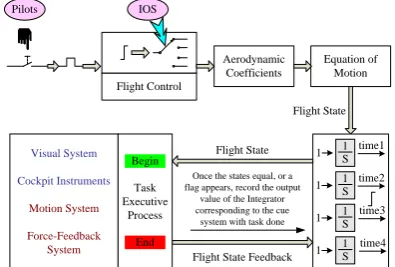
We verified the coordination with a way as call and back. We installed a press-button on the cockpit where the pilots could touch it easily. Before we started the test, we should control the A/C to fly high above the terrain. Once the pilots pressed down the button, the message was captured by a digital-In card and then a step signal was generated in the flight control model. The step signal had a very large final value, and replaced one of the normal control signals such as aileron, elevator, or rudder, which had specified by IOS and input by the pilots through the wheel and the pedal. Now the step signal with other control signals would enter to the aerodynamic coefficients block to join the computation, and then the equation of motion block. Because of the large value of the step signal, there must be a large angular acceleration on the output port of the equation of motion block described in detail in section IV. The large and unusual angular acceleration was detected to reset four Integrators to their initial conditions 0 and to hold the state of flight which would be sent to motion system, visual system, cockpit instruments, and force feedback system.
The cueing systems received the flight state at different time, and then refreshed their own output devices. To Visual system, a new frame was drawn on column screen by three projectors. To Cockpit Instruments system, new positions of pointers were updated. These two systems had a common method to deal with the process, which was executed in a loop. While a loop was executed over, a refresh task was done. So we added a UDP sender at the end of the loop. Once a refresh task was done, the data which the system received from the simulation model, the state of flight, such as the position of the A/C to Virtual system, was sent back to simulation model. Currently, the state of flight had been held in the simulation model. Then, the feedback state was compared with the held state. Once the two states were equal, the output value of the Integrator was recorded. This value was the time consumed by updating a new cue, which we concerned with, Fig.13 shows this method.
To motion system and force Feedback system, there was a little difference to the visual system and cockpit instruments system. We judged the task done by the acceleration of these systems. Because we only had a virtual prototype of Motion system, we measured the platform’s acceleration by adding a body sensor block on the centre of gravity of the upper platform in the SimMechanics model. To force feedback system, we measured the actuators control signal. When the acceleration of the platform or the control signal of the actuators exceeded a predefined value, a flag signal was sent back to the simulation model to record the output value of the corresponding Integrators. And then, we had the consuming time too.
We did the test for several times and with different control channels, roll, pitch and yaw. We got the longest time which every cueing system needed to refresh a frame. The result was exciting. The visual and virtual motion system could execute to completion with in sixty milliseconds, and the instruments and force-feedback system higher which reached 60Hz refresh rate. And the maximum difference of the delay time between the cueing systems was less than 30 milliseconds. Under this refresh rate and delay time, no one would feel uncomfortable for coordination. This result proved the design of our flight simulator based on COTS solution satisfied the coordination demand [13].
B. Fidelity Validation
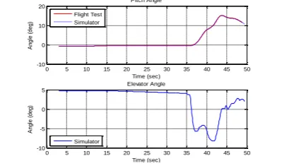
Fig.14 and 15 are a typical simulation about a normal taking off under some special conditions. The input commands are generated by a qualification test program.
The figures describe a pilot pulled the wheel at 35th
second to make the elevator to a negative degree, and then the pitch angle increasing, the aircraft began climbing. In this process, the simulation conformed to the flight test strictly. It indicated that the states of the A/C are in the tolerance defined by the Airplane Simulator Qualification. Other simulations such as cruise, landing and so on all had the same good performance and all conformed to the flight tests. Hence, the flight simulator had enough fidelity as a training device.
VI. CONCLUSION
In this paper, a distributed real-time simulation
framework and COTS-based simulation models
0 5 10 15 20 25 30 35 40 45 50 -10
-5 0 5
Time (sec)
A
n
g
le
(
d
e
g
)
Elevator Angle
0 5 10 15 20 25 30 35 40 45 50
-10 0 10 20
Time (sec)
A
n
g
le
(
d
e
g
)
Pitch Angle
Simulator Flight Test Simulator
Figure 15. Pitch angle vs. elevator angle during taking off.
system are presented. It successfully uses the mediator design pattern and commercial simulation development software. The mediator design pattern provides object
decoupling and minimizes simulation model
interdependencies which results in more simple designs and software which is more maintainable and extensible.. The application of mature and commercial simulation development software speeds up and
decreases the risk of engineering productions’
construction. As the modularity implementation nature of the method, it is easier to improve the fidelity of the flight simulator as better models becomes available or additional elements are included in the future, such as adding various wind models, more malfunction model and more logic functional model. The methods simultaneously provide an efficient software development approach for other real-time distributed simulation systems.
ACKNOWLEDGMENT
This work was supported by the fund of China's "World class university (985)" project (CDAZ98502211) and supported by Program for New Century Excellent Talents in University (NCET_04_0325).
REFERENCES
[1] Len Bass, Paul Clements, and Rick Kazman, Software
architecture in practice, MA: Addison Wesley, 2003.
[2] Gamma, E., R. Helm, R. Johnson, and J. Vlissides, Design
patterns: plements of reusable object-oriented software,
MA: Addison-Wesley, 1995.
[3] Wang Xinren, Jia Rongzhen, Peng Xiaoyuan, and Feng Qin, Flight real-time simulation system and technology, Press of Beihang University, Beijing, 2003.
[4] Rolfe, J.M. & Staples, K.J. Flight simulation, New York, NY: Cam-bridge University Press, 1986.
[5] Jane W.S. Liu, Real-time systems 1e, Prentice Hall, Inc., 2000.
[6] Wang Yongji, Chen Qiuping, “On schedulability test of rate monotonic and its extendible algorithms”, Journal of Software, vol. 2, pp. 799-814, 2004.
[7] Christopher J. Atkinson, Development of an Aerodynamic Table Lookup System and Landing Gear Model for the Cal
Poly Flight Simulator, PhD thesis, California Polytechnic
State University, San Luis Obispo, August 2002.
[8] Stevens, B.L. and F.L. Lewis, Aircraft Control and
Simulation, New York John, Wiley & Sons, 1992.
[9] The Mathsworks, Aerospace Blockset for Simulink, MATLAB USER’S GUIDE, September 2005.
[10] P D Bruce and M G Kellet, “Modeling and Identification of Nonlinear Aerodynamic Functions Using B-Splines”, UKACC International Conference on CONTROL, pp.907~912, September 1998.
[11] The Mathsworks, Spline Toolbox For use with MATLAB, MATLAB USER’S GUIDE, February 2003.
[12] Sjirk Holger KOEKEBAKKER, Model Based Control of a
Flight Simulator Motion System, PhD thesis, Delft
University of Technology, Delft, 2001, pp.31~118. [13] Federal Aviation Authority, Airplane Simulator
Qualification, Advisory Circular (AC) 120-40C, July 1995.
Shupeng Zheng, born in Henan, China, 1979, has got a master degree of computer science in 2004, at the School of Computer Science, Harbin Institute of Technology. He is a PhD candidate at the School of Mechatronics Engineering, Harbin Institute of Technology.
His main research interests include distributed system, real-time system and software architecture, etc. He has published more than 5 scientific papers about flight simulation and real-time system in various periodicals and conference proceedings.
Shutao Zheng, BSc, MSc, PhD, born in Henan, China, 1977, has got a PhD in Mechanical Engineering, at the School of Computer Science, Harbin Institute of Technology, 2009.He is lectorate at the School of Mechatronics Engineering, Harbin Institute of Technology.
He is an active researcher in flight simulation field. He has published many scientific papers in various periodicals and conference proceedings.
Junwei Han, Born in Liaoning, China, 1964, he received PhD from Harbin Institute of Technology in 1992. Now, he is a professor in School of Mechatronics Engineering, Harbin Institute of Technology, Harbin, China.