Computer Simulation of Sequential Impoundment
Process of Concrete-faced Rockfill Dam
Shouju Li
Key Lab. of Structural Analysis for Industrial Equipment, Dalian University of Technology, Dalian, 116023, China Email: [email protected]
Zichang Shangguan and Jizhe Wang
Institute of Civil Engineering, Dalian Ocean University, Dalian, 116023, China The Second Affiliated Hospital of Dalian Medical University, Dalian, 116027, China
Email: [email protected], [email protected]
Abstract—A procedure is presented for simulating the
sequential impoundment process of concrete-faced rockfill dam using nonlinear finite element method. The parameters of constitutive relationship of stress and strain are determined by tri-dimensional compression test in laboratory. The model applied in this study adopts the technique of element birth and death to simulate the sequential impoundment process of concrete-faced rockfill dam with time. Duncan and Chang's model is adopted herein to define the non-linear stress-strain behaviour of the rockfill materials and is used to simulate the prototype behavior of various components of the dam in sequential nonlinear analysis and some representative results are presented.
Index Terms—computer simulation, sequential
impoundment process, model parameters
I. INTRODUCTION
Modern studies on simulation make full use of computer and system simulation technologies, which makes it possible to perform the simulation investigation for CFRD on computer and provides a favorable platform for organizing the construction process with complex physical and mechanical problems. Rockfill has been used in the construction of dams for over 150 years [1]. The concrete-faced rockfill dam was used with increasing frequency in recent years, in many parts of the world. In addition to being a natural choice where suitable clayey core material is not available in the vicinity of the project, the CFRD has in many cases been found to be the least-cost alternative dam design. As worldwide experience is accumulating on the long-term performance of CFRD, their popularity may well increase in coming years [2]. This widespread current use of the CFRD results from increased recognition that: (1) The modern CFRD is a very good dam type from all technical standpoints; and (2) the CFRD is often the lowest-cost dam type. The previous problems of high settlement and leakage of the older, dumped (uncompacted) rockfill dam with concrete face have been overcome. The CFRD is being used for reservoirs for all purposes and sizes, from small irrigation
pressures increase. With increasing confining pressures, the dilation decreases and the contraction eventually prevails. Initial strength parameters show a nonlinear relationship with confining pressures when the pressures are relatively low. Shear strength parameters decrease with increasing confining pressures [10]. Centrifuge model tests were conducted for a rockfill dam model in order to investigate behavior of dam during first reservoir filling and the typical test result was simulated by using a consolidation analysis method coupled with an elastoplastic model for unsaturated geo-materials [11]. Postconstruction deformations of some rockfill dams with a slightly inclined or central till (moraine) core are presented by Dascal. Although deformation still continues, even 30 years after dam construction, for all practical purposes the settlement could be nevertheless considered to cease 36 months following the end of construction [12]. A recently developed constitutive model for rockfill has been implemented in a coupled finite element program, which solves the hydromechanical problem for general unsaturated conditions. The performance of the dam during construction and impoundment has been analyzed. The agreement between calculated and measured displacements indicates that the capabilities of the constitutive models and computational tools used [13]. Szostak Chrzanowski presented a study of behaviour of the Shibuya Dam in P. R. China, the tallest (233 m) concrete face rockfill dam in the world using results of monitoring and FEM analysis [14]. An elasto-plasticity damage interface element, a numerical format of the EPDI model, is described for numerical analysis of a CFRD that can trace the separation and re-contact between the face slab and the cushion layer at the interface [15]. A study of the post-construction crest settlements and deflections of 68 rockfill dams has been made in order to assess the usefulness and accuracy of the prediction of such deformations using empirical equations by Clements. Comparisons of predicted and observed movements show that use of empirical equations can lead to large errors [16]. A neural network model has been developed for the prediction of relative crest settlement of concrete-faced rockfill dams using 30 databases of field data from seven countries. The settlement values predicted using the optimum artificial neural network model are in good agreement with these field data [17]. A method was presented for estimating the modulus of compacted rockfill in dams based on the particle size, unconfined compressive strength of the rock, compaction layer thickness, compactive effort, and the applied vertical stress [1]. The settlement and slaking problems of the ataturk dam were investigated both in the field and the laboratory using soil and rock mechanical techniques by Cetin [18]. Standard proctor tests were run to determine the optimum moisture content at which the highest dry density (best compaction) is obtained during compaction of the impervious clay core. Consolidation tests were performed on undisturbed compacted clay core samples to determine if the field compaction of the clay core was done to the standards determined in the
laboratory. Unconfined compression tests were run on the two different basalts used in the rock-fill section of the dam to determine their unconfined compressive strengths [19]. It has been known pore water pressure developed during this time in the impervious section is an important factor in slope stability analysis of dams. The slope stability analysis in this research is done with Geo-slope software [20].
This paper is organized as follows: Section 1 gives some review and remark about numerical simulation of CFRD. Section 2 presents the basic characteristics of Pushihe CFRD, general construction plan and layout, sequential impoundment phase and time schedule, main properties of rockfill materials. Section 3 briefs the constitutive model used for rockfill dam body. Duncan EB model is employed to describe the non-linearity of rockfill materials. The parameters of constitutive relationship of stress and strain are determined by tri-dimensional compression test in laboratory. Section 4 numerically simulates impoundment process of concrete-faced rockfill dam. The stress and deformation distributions are shown in the section. Section 5 draws conclusions and recommendations.
II. DAM CHARACTERISTICS
Pushihe pumped storage power station is located in Kuandian county, Liaoning province, China, 60km of Dandong city, on Pushihe River. The main purpose is to provide energy during periods of high electrical demand. Pushihe dam is 78.5m high from river bed. The side slopes are 1:1.4 both in the upstream and downstream faces. The crest extends 714m. Construction of the dam body filled with rock was started in July 2007 and finished in Novermber 2008. The impoundment process of the dam lasted for 15 months approximately. Fig. 1 shows general construction plan and layout of the dam. Basic geological unit in the dam site is composed of granite. Table І lists main mechanical parameters of rock foundation. Table П lists main properties of rockfill materials.
TABLE I.
MAIN MECHANICAL PARAMETERS OF ROCK FOUNDATION
Rock
type kg/mDensity/ 3 ratio /% Porosity strength/MPa Compression
SWG WWG SLWG
2630 2730 2670
1.67 0.18 0.75
The CFRD is composed of cushion zone, transition zone, main rock fill zone, downstream rockfill zone and road foundation rockfill zone. The main purpose of cushion zone of finer rock directly under the slab is to provide uniform and firm support for the concrete slab. Maximum particle size of cushion zone is 100mm. Layer compaction thickness of cushion zone is 400mm. The rockfill embankment is in four zones of increasing layer thickness to give a desirable transition of compressibility and permeability from upstream to downstream. The transition zone is located in between of cushion zone and main rockfill zone. The main purpose of it is to limit the size of voids and ensure that materials of cushion zone could not be washed into large voids in the main rockfill. Maximum particle size of transition zone is 300mm. Layer compaction thickness of transition zone is 400mm. Because most of the water loads passes into the foundation through the upstream shell, it is desirable that the compressibility of main rockfill zone be made as low as practical to minimize slab settlement. Maximum particle size of main rockfill zone is 600mm. Layer compaction thickness of main rockfill zone is 800mm. The downstream rockfill zone takes negligible water load, and its compressibility has little influence on the settlement of the face slab. Maximum particle size of downstream rockfill zone is 800mm. Layer compaction thickness of downstream rockfill zone is 1000mm. It needs 8 passes of a 10-t smooth steel-drum vibratory roller to give satisfactory performance for any rockfill zone. Fig. 2 shows particle size distribution for main rickfill zone and downstream rockfill zone. Table Ⅲ lists general characteristics of the Pushihe Dam.
The main rockfill zone at the upstream is the main part of the dam body. It provides a support for hydrostatic loads transmitted from the cushion zone and transition zone. The downstream rockfill zone is filled with relatively poor quality materials since this zone responds smaller load. The cushion and transition zones are filled with fresh granite blasted from tunneling. Table Ⅳ lists construction phase and time. Fig. 3 shows construction sequence of Pushihe Dam. Fig. 4 and 5 depict Pushihe dam during construction and after finial completion (upstream show).
TABLE IV.
CONSTRUCTION PHASE AND TIME
Notes: M-main rockfill, D-downstream rockfill, R-road rockfill. TABLE III.
GENERAL CHARACTERISTICS OF THE PUSHIHE DAM
General characteristics Depiction Type of dam
Purpose Crest elevation
Crest length Crest width Height from foundation
Max. water level Min. water level Reservoir area Installed capacity
Rockfill dam pumped storage
395.5m 714.0m 8.0m 78.5m 393.6m 360.0m 0.442km2
1200MW
0 20 40 60 80 100
0 100 200 300 400 500 600 700 800 Particel Size/mm
C
umu
la
tiv
e r
at
io
/%
Downstrean rockfill M ain rockfill
Figure 2. Particle size distribution for main rickfill zone and downstream rockfill zone.
TABLE II.
MAIN PROPERTIES OF ROCKFILL MATERIALS
zone material ρ/kg/m3 D/mm φ/% t/mm
MR DSR CR TR
A B C C
2112 2094 2255 2227
600 800 100 300
20.0 21.0 18.0 19.0
800 1000
400 400 Note: A represents slightly weathered Granite; B represnets weakly or strongly weathered Granite, C represents fresh Granite blasted from tunneling. MR- Main rockfill. DSR- Down stream rockfill. CR- Cushion. TR- Transition. D is maximum particle size, t is compaction thickness.
Ⅲ. CONSTITUTIVE MODEL AND PARAMETERS OF
ROCKFILL MATERIALS
In order to provide a simple framework encompassing the most important characteristics of rockfill stress-strain behaviour using material parameters available from conventional laboratory tests, Duncan and Chang developed a hyperbolic model based on the hyperbolic equation proposed by Kondner [20]. Because of its simplicity and wide applicability, Duncan and Chang's model is adopted herein to define the non-linear stress-strain behaviour of the rockfill materials. The stress-strain behavior of conditioned rockfill depends on a number of different factors including density, water content, structure, drainage conditions, strain conditions, duration of loading, stress history, confining pressure,
and shear stress. The hyperbolic equation proposed by Kondner is expressed as follows[21]
1 3
(
)
a b
ε
σ σ
ε
−
=
+
(1)Where σ1 and σ3 are the major and minor principal
stresses; ε is the axial strain; a and b are constants whose values may be determined experimentally. By expressing the parameters a and b in terms of the initial tangent modulus value and the compressive strength, Eq. 1 can be rewritten as follows
1 3
1 3
(
)
1
[
]
(
)
f
i f
R
E
ε
σ σ
ε
σ σ
−
=
+
−
(2)
Where Rf is the failure ratio, which always has a value
less than unity, the value of Rf has been found to be
between 0.75 and 1.00. (σ1-σ3)f is the compressive
strength. Experimental studies by Janbu have shown that the relationship between initial tangent modulus and confining pressure may be expressed as
3
(
)
ni a
a
E
Kp
p
σ
=
(3)Where Ei is the initial tangent modulus; pa is the
atmospheric pressure expressed in the same pressure units as Ei; k is a modulus number; n is the exponent
determining the rate of variation of Ei with σ3. If it is
assumed that failure will occur with no change in the value of σ3, the relationship between compressive
strength and confining pressure may be expressed conveniently in terms of the Mohr-Coulomb failure criterion as
3
1 3
2 cos
2
sin
(
)
1 sin
f
c
ϕ
σ
ϕ
σ σ
ϕ
+
−
=
−
(4)Where c and ϕ are the Mohr-Coulomb strength parameters. Eqs. 3, 4, combination with Eq. 2, provide a means of relating stress to strain and confining pressure by means of the five parameters K, n, c , ϕ and Rf. The
stress-strain relationship may be employed very conveniently in incremental stress analyses because it is possible to determine the value of the tangent modulus corresponding to any point on the stress-strain curve. If the value of the minor principal stress is constant, the tangent modulus may be expressed as
1 3
(
)
t
E
σ σ
ε
∂
−
=
∂
(5)Figure 5. Pushihe CFRD after finial completion (upstream show). Figure 4. Pushihe CFRD during construction.
Where Et is the tangent modulus of rockfill materials.
The values of tangent modulus and Poisson ration for any stress condition may be expressed as
1 3 2
3
3
(1 sin )(
)
(
) [1
]
2 cos
2
sin
f n t a a
R
E
Kp
p
C
ϕ σ σ
σ
ϕ
σ
ϕ
−
−
=
−
+
(6)3 2 lg( ) 1 a i G F p A σ − ν =
− (7)
Where νi is tangent Poisson ration of rockfill for
different stress condition. G and F are two constants determined by test data. And constant A is computed by
1 3
1 3
3
3
(
)
(
)(1 sin )
[
][1
]
2 cos
2
sin
f a a
D
A
R
Kp
p
c
σ σ
σ σ
ϕ
σ
ϕ
σ
ϕ
−
=
−
−
−
+
(8)Where D is a constant. The bulk modulus can be expressed as follows
3
(
)
mt b a
a
B
k p
p
σ
=
(9)Where Bt is bulk modulus, kb and m are two constants
for rockfill materials. The expression for tangent and bulk modulus may be employed very conveniently in incremental stress analyses, and constitutes the essential portion of the stress-strain relationship. The test dada shows that internal friction angle of rockfill has a relationship with the confining stress, which can be expressed by
3 0
= -
lg(
)
a
p
σ
ϕ ϕ
Δ
ϕ
(10)Where ϕ0 and Δϕ are two constants for rockfill
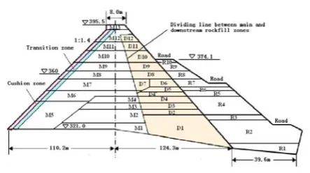
materials. Laboratory tests were conducted in a tree-dimensional compression machine to study the characteristics of the rockfill materials. Model parameters of nonlinear constitutive relationship of rocfill are listed Table Ⅴ. Fig. 6 shows stress-strain relationship of main rockfill zone. Fig. 7 shows mesh of finite element model.
Ⅳ.NUMERICAL SIMULATION OF IMPOUNDMENT PROCESS OF CONCRETE-FACED ROCKFILL DAM
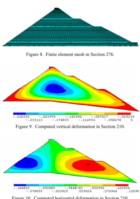
The model applied in this study adopts the technique of element birth and death to simulate the impoundment process of concrete-faced rockfill dam with time. All elements must be created, including those rockfill to be born in later stages of the analysis. The method proposed herein does not remove elements to achieve the ‘‘element death’’ effect. Instead, the method deactivates them by multiplying their stiffness by a severe reduction factor. Although zeroed out of the load vector, element loads associated with deactivated elements still appear in element-load lists. Computational procedure follows the construction sequence as shown in Fig. 3. Fig. 8 shows Finite element mesh in Section 276. Fig. 9 and 10 illustrate the computed vertical and horizontal displacements. In the upstream and downstream parts, the computed maximum horizontal displacement is -155mm (directional upstream) and 112mm (directional downstream), respectively. The maximum horizontal displacements of directional upstream and downstream are -124mm and 130mm, respectively. The maximum vertical displacement is 372mm, which is located in the middle of dam height and is about 0.50% of dam height.
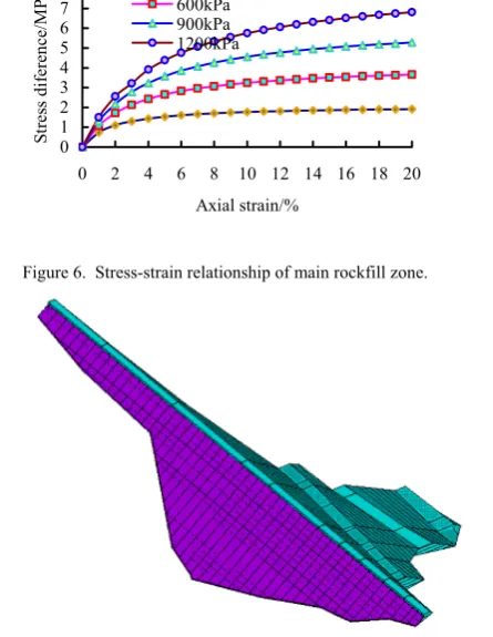
Figure 7. Finite element model in tree dimension.
0 1 2 3 4 5 6 7 8
0 2 4 6 8 10 12 14 16 18 20
Axial strain/% St re ss d ife re nc e/ M
Pa 300kPa600kPa
900kPa 1200kPa
Figure 6. Stress-strain relationship of main rockfill zone.
TABLE V.
MODEL PARAMETERS OF NONLINEAR CONSTITUTIVE RELATIONSHIP OF
ROCFILL
Material
zones γ/m/Kn 3 φ/° Δφ/° K n Rf Kb m
The horizontal displacement of dam is zero at the central line of dam section and increases towards both upstream and downstream faces, as shown in Fig. 10. The maximum computed horizontal displacements do not occurs at the dam faces, which is not same as the calculated results from reference [6]. The maximum computed horizontal displacement at the upstream face of dam can reach 0.13m. The horizontal displacement at the upstream face of dam induced from sequential impoundment process must be considered in order to make upstream face of dam to a designed straight line after rockfill construction and ensure concrete slab to contact rockfill during casting concrete slab phase and service period. Fig. 11 shows shear stress distribution in Section 276, Fig. 12 and 13 show distribution of the first principal stress and the third principal stress in Section 276.
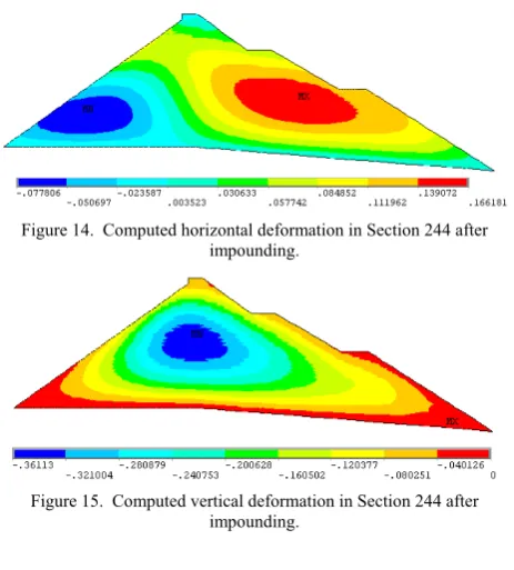
The shear stress is zero at the central line of dam and increases towards the upstream and downstream faces, until the maximum value of both negative and positive shear is reached at points midway between central line and upstream or downstream face, as shown in Fig. 11. The maximum shear stress is 0.23 MPa. The third principal stress (compression stress) increase with the increase of deposition depth. The maximum occurs at the contacting face of dam body with rock foundation, on the central line of dam section. The maximum value of compression stress is 1.39 MPa, as shown in Fig. 13. The stress state of dam body is governed by compression stress. The tensile stress zone occurs only at superficial layer of dam body. The depth of tensile stress zone is less than 5m, as shown in Fig. 12. The maximum tensile stress of dam body is only 3kPa. If the contour line of upstream surface is constructed according to design contour line, the shape of contour line of upstream surface will become curve shape as shown in Fig. 11 when the rockfill of CFRD is filled up. The maximum error can reach 155mm, which will make casting concrete-faced slab be very difficult. The adjustment of impounding contour line is performed during the rockfill construction period according to calculated horizontal deformation. The width of dam under and above neutral point must decrease or increase, respectively. The application of numerical simulation to Pushihe CFRD indicates the effectiveness and necessity. Fig. 14 and 15 depict the computed horizontal and vertical deformation after dam impounding.
Figure 13. Distribution of the third principal stress in section 220. Figure 12. Distribution of the first principal stress in Section 220.
Figure 11. Shear stress distribution in Section 220. Figure 10. Computed horizontal deformation in Section 210.
Ⅵ. CONCLUSIONS
1) By using the birth and death of elements technique, sequential impoundment process of a concrete-face rockfill dam is numerically analyzed. Duncan EB model is employed to describe the non-linearity of rockfill materials. The parameters of constitutive relationship of stress and strain are determined by tri-dimensional compression test in laboratory.
2) Numerical simulation shows that the maximum computed horizontal displacement is 0.155m. The location of maximum computed horizontal displacement is 0.27 times of dam height. The maximum computed vertical displacement is 0.372m and 0.50% of dam height and occurs at 0.45 times of dam height, on the central line of dam section.
3) The maximum computed horizontal displacement at the upstream face of dam can reach 0.13m. The horizontal displacement at the upstream face of dam induced from sequential impoundment process must be considered in order to make upstream face of dam to a designed straight line after rockfill construction and ensure concrete slab to contact rockfill during casting concrete slab phase and service period.
4) The third principal stress (compression stress) increase with the increase of deposition depth. The maximum occurs at the contacting face of dam body with rock foundation, on the central line of dam section. The maximum value of compression stress is 1.39 MPa. The stress state of dam body is governed by compression stress. The tensile stress zone occurs only at superficial layer of dam body. The depth of tensile stress zone is less than 5m. The maximum tensile stress of dam body is only 3kPa. The maximum shear stress is 0.23 MPa.
5) Based on numerical simulation of sequential impoundment process, the Pushihe CFRD is constructed. The practical application validates the accuracy and
effectiveness of sequential impoundment simulation with nonlinear finite element method.
REFERENCES
[1] G. Hunter, R. Fell, “Rockfill Modulus and Settlement of Concrete Face Rockfill Dams,” Journal of Geotechnical and Geoenvironmental Engineering, vol. 129, pp. 909–917, 2003.
[2] J. B. Cooke, “Progress in rockfill dams (18th Terzaghi lecture),” J. Geotech. Eng., vol. 110, pp. 1383–1414, 1984. [3] M. W. Seo, I. S. Ha, Y. S. Kim, “Behavior of Concrete-Faced Rockfill Dams during Initial Impoundment,” Journal of Geotechnical and Geoenvironmental Engineering, vol. 135, pp. 1070–1081, 2009.
[4] H. F. Xing, X. N. Gong, X. G. Zhou, “Construction of Concrete-Faced Rockfill Dams with Weak Rocks,” Journal of Geotechnical and Geoenvironmental Engineering, vol. 132, pp. 778–785, 2006.
[5] A. Varadarajan, K. G. Sharma, K. Venkatachalam, “Testing and Modeling Two Rockfill Materials,” Journal of Geotechnical and Geoenvironmental Engineering, vol. 129, pp. 206–218, 2003.
[6] S. Ozkuzukiran, M. Y. Ozkan, M. Ozyazicioglu, “Settlement behaviour of a concrete faced rock-fill dam,” Geotechnical and Geological Engineering, vol. 24, pp. 1665–1678, 2006.
[7] B. Y. Zhang, J. G. Wang, R. F. Shi, “Time-dependent deformation in high concrete-faced rockfill dam and separation between concrete face slab and cushion layer,” Computers and Geotechnics, vol. 31, pp. 559–573, 2004. [8] J. B. Cooke, J. L. Sherard, “Concrete-Face Rockfill Dam:
II. Design,” Journal of Geotechnical Engineering, vol. 113, pp. 1113–1132, 1987.
[9] H. L. Liu, A. Deng, Y. Shen, “Shear behavior of coarse aggregates for dam construction under varied stress paths,” Water Science and Engineering, vol. 1, pp. 63–77, 2008. [10] Y. Kohgo, A. Takahashi, I. Asano, T. Suzuki, “FEM
Consolidation Analysis of Centrifuge Test for Rockfill Dam Model During First Reservoir Filling,” Unsaturated Soils, vol. GSP 147, pp. 2312–2323, 2006.
[11] O. Dascal, “Postconstruction Deformations of Rockfill Dams,” Journal of Geotechnical Engineering, vol. 113, pp. 46–59, 1987.
[12] E. E. Alonso, S. Olivella, J. Hugas, “Modelling the behaviour of an earth and rockfill dam during construction and impoundment,” Unsaturated Soils: Numerical and Theoretical Approaches, vol. 94, pp. 269–287, 2005. [13] A. Szostak_Chrzanowski, N. Deng, M. Massiear,
“Monitoring and Deformation Aspects of Large Concrete Face Rockfill Dams,” In: 13th FIG Symposium on Deformation Measurement and Analysis, LNEC, Lisbon, 2008, pp. 12–15.
[14] G. Zhang, J. M. Zhang, “Numerical modeling of soil– structure interface of a concrete-faced rockfill dam,” Computers and Geotechnics, vol. 36, pp. 762–772, 2009. [15] R. P. Clements, “Post-construction deformation of rockfill
dams,” Journal of Geotechnical Engineering, vol. 110, pp. 821–840, 1984.
[16] Y. S. Kim, B. T. Kim, “Prediction of relative crest settlement of concrete-faced rockfill dams analyzed using an artificial neural network model,” Computers and Geotechnics, vol. 35, pp. 313–322, 2008.
[17] J. L. Sherard, J. B. Cooke, “Concrete-face rockfill dam: I. assessment,” Journal of Geotechnical Engineering, vol. 113, pp. 1096–1112, 1987.
Figure 15. Computed vertical deformation in Section 244 after impounding.
[18] H. Cetin, M. Laman, A. Ertunc, “Settlement and slaking problems in the world’s fourth largest rock-fill dam, the Ataturk Dam in Turkey,” Engineering Geology, vol. 56, pp. 225–242, 2000.
[19] A. Zomorodian, K. Sahebzadeh, A. Ooria, “Effect of Number of Layers on Incremental Construction Analysis of Earth and Rock Fill Dams,” Electronic Journal of Geotechnical Engineering, vol. 11, 2006.
[20] J. M. Duncan, C. Chang, “Nonlinear analysis of stress and strain in soils,” Journal of the Soil Mechanics and Foundations Division, vol. 96, pp. 1629–1653, 1970. [21] R. L. Kondner, “Hyperbolic stress-strain response:
cohesive soils,” Journal of the Soil Mechanics and Foundations Division, vol. 89, pp. 115–143, 1963.
Shouju Li was born in Shenyang,
Liaonong Province, China, on October 3, 1960. He received the Ph. D. degree in Engineering Mechanics from the Dalian University of Technology, Dalian, China, in 2004.
He was Professor at Department of Engineering Mechanics, Dalian University of Technology form 2008. He teaches and conducts research in the areas of neural network,
intelligent optimization, parameter identification applied to soil mechanics and underground engineering fields.
Zichang Shangguan was born in Fushun,
Liaonong Province, China, on May 29, 1959. He received the Ph. D. degree in Civil Engineering from the Dalian University of Technology, Dalian, China, in 2011.
His research interest is Geotechnical Engineering, Structure Engineering and Intelligent Computing. He is working at Dalian Ocean University as a Professor and an Associate Dean of Civil Engineering Institute.
Jizhe Wang was born in Shenyang, Liaonong Province, China, on April 1, 1968. He received the Ph. D. degree in Medical Science from the China Medical University, Shenyang, China, in 2005.
He is working at the second affiliated hospital of Dalian Medical University as a Professor and an associate dean of ear-nose-throat department.