5
IV
April 2017
Technology (IJRASET)
Causal Productions
62
Design and Implementation of PLC Based Seal
Packing Process
Chaitanya Umesh Prabhu Gaunker
Electronics and Telecommunications Department, Goa College of Engineering, Farmagudi, Ponda Goa, India- 403401
Abstract— this paper deals with the PLC based approach to put and inspect the integrity of LPG cylinders packing seal. New method was proposed for sealing the blue colour plastic cover. This method currently meets industries requirement for very high speed, accurate and quality inspection with very low associated production cost. This new system will be based on Allen Bradley PLC which will do the work more efficiently. The PLC hardware system will be controlling, and the PLC ladder program is designed, and the software will be used to do the monitoring. This PLC based seal packing process will be very stable and reliable, along with it there will be distant monitoring, and operator convenience.
Keywords— Allen Bradley PLC, Inductive Sensor, SCADA, Sealing Unit, Solenoid Valve I. INTRODUCTION
This LPG gas cylinders are very essential as they are used in day today’s life. Over the past few years the system has been using a pneumatic way for sealing the valve of cylinder. In recent years the demand of LPG cylinders has increased and the plant is expected to produce more number of LPG cylinders per day. Pneumatic based sealing unit has its own limitation in terms of number of LPG cylinders per hour, so in order to increase the capacity, there was a need for new idea which would make the process faster compared to the existing one. The entire new system was designed based on Allen Bradley PLC to increase the production. Advantage of doing this entire process on programmable logic controller are very high as the program can be changed anytime depending on the industries need. Person can put password to his work so that no other person can alter his work in order to protect further damage to the system. PLC can withstand in harsh temperature and conditions [1].
II. DESIGNING
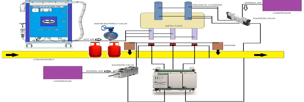
[image:2.612.48.538.530.694.2]The block diagram is shown in Fig. 1. Conveyor belt will be carrying the LPG cylinders. Three inductive sensors are placed right below the sealing unit. Once the LPG cylinders reach under the metal plate, PLC will stop the cylinders by turning on the stopper. Stoppers are pneumatic cylinders which has a piston inside it and they can take up to 10 bar maximum pressure. This stoppers will stop the movement of LPG cylinders until the sealing is carried out. The pneumatic cylinders mounted on the metal plate will push the gun to come down along with the metal plate. When the gun comes in contact with the LPG cylinders, wafer butterfly valve will be turned on and it will initiate the flow of hot air through the small openings onto the seals. Baliga heater which is specially used in such industries will continuously supply the hot air (250°C) required for the sealing purpose.
Technology (IJRASET)
Causal Productions
63
Once the sealing is done, PLC will turn off the stopper so that sealed LPG cylinders can move forward. It will pull the metal plate upwards to prepare for the next set of LPG cylinders. Solenoid valves are basically used to control this pneumatic cylinders. Five by two solenoid will control the pneumatic cylinders mounted on top of the metal plate. It will have a continuous air supply from the compressor. Two by two solenoid valve will be controlling the stoppers.
A. Programmable Logic Controller
PLC is the true platform for the automation field. Because of its design it has numerous advantages over the microprocessors, general purpose computers. PLC is designed for an industrial environment and was manufactured to deal with the harsh conditions which could be electrical noise, electromechanical interferences, mechanical vibrations, extreme temperatures and non-condensing humidity of 95% [2]. The PLC platform used in this study is Allen Bradley microtransistor820. This type of PLC processors and hardware provide the required processing power to execute the complex automation algorithms.
Since PLC works in sequential fashion it can easily recover from the power failure since it does not have any boot-up procedure [3]. This PLC has eight digital inputs and six digital outputs. It also has four analog input and one analog output. All PLCs work on 24V dc supply. Ethernet port is available for PC to PLC communications. It has 100 kilo byte memory reserved for programming. This type of PLC can work under -20°C to 60°C temperature. It has 4 megabyte of memory capacity. It gives 1600 mA of output current.
B. Inductive Sensor
This inductive sensors are like metal detecting sensors. It has a range of about 8 mm. This sensors are round shaped with 12 mm diameter. This sensors are PNP (Normally Open) output. Three sensors are used so that at a time 3 cylinders can enter the sealing unit.
C. Solenoid Valve
As we discussed above there are two types of solenoid valves used in our system. Valves are like the executive body in the control process. They largely determine the response of that particular system. One type of solenoid valve we have used for controlling the stoppers is two by two Festo solenoid valve and the other type of solenoid valve used for controlling the metal plate pneumatic cylinders is five by two Festo solenoid valve.
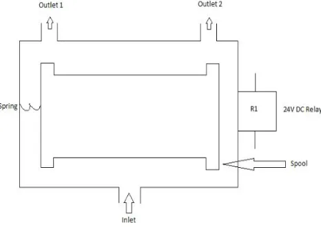
[image:3.612.196.429.487.652.2]For two by two solenoid valve inlet will get a continuous air supply from the compressor. This solenoid valve will have two outlets which are specifically named in the Fig. 2. This two outlets are connected to the top and bottom of the pneumatic cylinders placed at the start and at the end of sealing unit. It will have a spring on one side and a 24V DC relay on the other side. If the relay R1 is turned ON it will attract the spool towards it, which will cause the air entering from inlet to go to outlet 2. This outlet 2 will be connected to pneumatic cylinder and it will cause piston to move downwards, thus the piston will push the pusher out to block the movement of LPG cylinders.
Fig. 2 Schematic diagram of two by two solenoid valve
Technology (IJRASET)
Causal Productions
64
of piston, it will pull the pusher inside and the blocked path of the LPG cylinders will be freed.
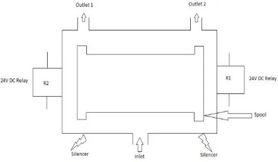
For five by two solenoid valve inlet will get a continuous air supply from the compressor. This type of solenoid valve will have two outlets, two relays and two silencers which are specifically named in the Fig. 3. The two outlets of this solenoid valve will be connected to top and bottom of pneumatic cylinders mounted on top of the metal plate. It will have two 24V DC relays R1 and R2 mounted on both the side of the valve.
[image:4.612.169.454.196.362.2]If the relay R1 is turned ON it will attract spool towards its side and outlet 2 will be open. The air entering through inlet will pass through outlet 2. This air will be passed to the top of pneumatic cylinders mounted on top of the metal plate. This air will force the piston to move downwards thus taking the metal plate closer to the LPG cylinders.
Fig. 3 Schematic diagram of five by two solenoid valve
Once the metal plate comes in contact with the LPG cylinders, wafer butterfly valve will be turned ON and it will allow the flow of hot air through stainless steel pipes. This hot air will be used to apply the seals onto the cylinders. Once the seals are applied which often takes few seconds, the control valve will be turned OFF and the flow of hot air will be restricted.
As the seals are applied, PLC will excite the relay R2 thus the spool will be attracted towards the R2. This will open the outlet 1 which is connected to the bottom of the pneumatic cylinder. Now the air entering through the inlet will be passed on to bottom of the pneumatic cylinders and it will force the piston to move upwards thus pulling the metal plate up. Metal plate will come to its normal position and air which is trapped inside the pneumatic cylinder will be extracted through the silencers which are placed at the bottom of the valve.
D. Baliga Heater
The Flame Proof Portable hot air sealing system consists of FLP electrical control unit, FLP hot air chamber, pneumatic accessories, insulated Teflon hose, sealing gun and FLP plug and socket. The system is electro pneumatic, which provides a high degree of safety as required in hazardous area like LPG bottling plant. The initial warm up time is approximately 8-10 minutes after which sealing can be started. The FLP electrical control unit, hot air chamber and pneumatic components are housed in a fabricated sheet steel panel and mounted in a trolley, which makes system portable to move to any desired location easily. A flame proof plug is provided at the end of electrical cable so that the system can be connected to the matching FLP socket installed in the plant.
E. Wafer Butterfly Valve
Wafer Butterfly valve is used to trim or control ambient or preheated air. The valve can be supplied with a hand lever and linkage for automatic control. When sizing wafer butterfly valve for automatic control, normal practice is to size for a valve differential pressure of 10-20% of the total available air pressure. It can handle up to 1200ºF of preheated air.
III. ALGORITHM
A. When start button is pressed, the first thing it should do is to check the temperature. The temperature should be above 250ºC.
B. When sensor 3 detects the LPG cylinder stopper 2 will be high.
Technology (IJRASET)
Causal Productions
65
D. Five by two solenoid valve will force the metal plate to come down. Once the seal is applied the same valve will force it to go up.
E. Once the seal is applied stopper 2 will go low.
F. Exceptional Cases
1) If sensor 3 is high and sensor 2 and sensor 1 don’t get any signal for 3 seconds, stopper 1 will be high along with stopper 2 and then the seal will be applied.
2) If sensor 3 and sensor 2 are high but sensor 1 is low and doesn’t get any signal for 3 seconds, stopper 2 and stopper 1 will be high and sealing will take place.
3) There will be emergency stop button which will halt the operation.
IV. SCADA APPLICATION
The SCADA (Supervisory Control and Date Acquisition) is mainly designed to visualize and control processes, production sequences and machines and troubleshooting. SCADA implementation in automation systems improves the planning ability and also enables the operation, control and visualization of the automation system from one outdoor [4]. In order to observe and control the sealing process we will be using Wonderware InTouch 10.0 SCADA software. This software is widely used in the automation industries.
[image:5.612.132.489.538.701.2]When the InTouch software is start up, Application Manager Page will show all the existing projects and will give us the opportunity to make a new one. In Application Manager Page projects, modes, screen resolutions and versions can be checked [5]. InTouch SCADA software Application Manager Page is shown in Fig. 4. InTouch SCADA software is run in Window Viewer mode. In Window Maker Page, there will be a Runtime icon, by clicking that the simulation can be carried out.
Fig. 4 Application Manager Page of SCADA InTouch 10.0
InTouch SCADA software will have a window script option where in you have to write the script. After selecting the wizards required for the project, you have to name them in a specific order [6]. It is shown in Fig. 5.
Technology (IJRASET)
Causal Productions
66
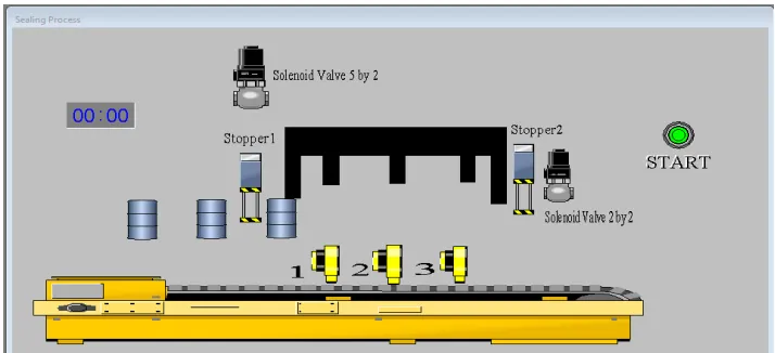
[image:6.612.132.491.142.302.2]Once the naming is done then you are free to program them. There will be two screens, ‘On Show’ and ‘While Showing’. Under ‘On Show’ screen you have to define the initial conditions whereas in ‘While Showing’ you have to write the actual program. Three LPG cylinders are entering the sealing unit as shown in Fig. 6. Once they enter the unit, seals will be applied onto the LPG cylinders as shown in Fig. 7. Once the seals are applied, new cylinders will enter the sealing unit.
[image:6.612.132.490.335.490.2]Fig. 6 Three LPG cylinders entering the sealing unit
Fig. 7 Sealing of LPG cylinders
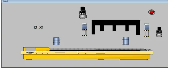
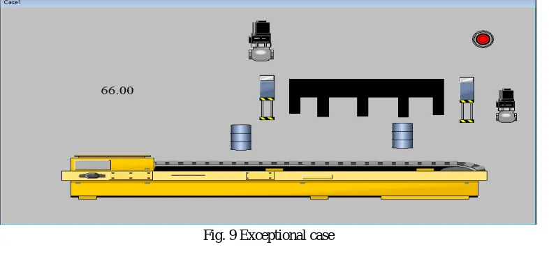
[image:6.612.163.462.582.701.2]There will be exceptional cases as explained in algorithm part. When there will be a lot of delay between the two LPG cylinders, the unit cannot afford to wait for all three cylinders to come at same time. If there is a delay of more than three seconds it will seal the LPG cylinder which have entered the unit and will stop the next cylinder from entering the unit as shown in Fig. 8 and Fig. 9. The cylinder which was waiting outside the sealing unit can enter the unit once the cylinder which was present inside the unit is sealed.
Technology (IJRASET)
[image:7.612.119.512.81.263.2]Causal Productions
67
Fig. 9 Exceptional case
V. CONCLUSIONS
The main ideas of this study are designing and implementation of PLC based seal packing process by using the industrial production equipment and visualization and controlling the system via SCADA System. This SCADA System enables us to control and manage the sealing unit from a distance.
Using the pneumatic system the sealing unit could seal around 1600 LPG cylinders per hour, but because of this PLC based system, the unit could seal around 1800 LPG cylinders per hour thus meeting the demand.
VI. ACKNOWLEDGMENT
I am deeply indebted to my guide, Prof. Devendra Sutar, Professor, Department of Electronics and Telecommunication Engineering, and Mr. Manish Lenpale, Plant manager, H.P.C.L. Kundai Goa, for allowing me to carry out this project under his supervision. He has given me a confidence to take up this project and guided me at the times of difficulty.
I thank my teachers, who have taught enthusiastically at the Goa College of Engineering. I also thank Dr. Hassanali Virani, (Head of the Department), Department of Electronics and Telecommunication Engineering, and Dr. Vinayak N. Shet (Principal), Goa College of Engineering.
REFERENCES [1] K. T. Erickson, “Programmable logic controllers”, IEEE Potentials, 1996.
[2] Curtis Parrott, Ganesh K. Venayagamoorthy. (2003). Real-Time Implementation of Intelligent Modelling and Control Techniques on a PLC Platform. Presented at IEEE International Conference on Industrial Technology.[Online].Available: http://ieeexplore.ieee.org/document/4658952/
[3] K. Erickson, Programmable Logic Controllers: An Emphasis on Design and Applications, Rolla: Dogwood Valley Press, 2005, pp. 1-20. [4] DOGANOLGU C., YENITIPE R., “SCADA Systems and an Application”, Graduation Project, M. U. Istanbul, 2003.
[5] R. Yenitepe. (2004, June). An Application of SCADA System on a MT educational MPS unit. Presented at Mechatronics, 2004. ICM’04. Proceedings of the IEEE International Conference. [Online]. Available: http://ieeexplore.ieee.org/document/1364487/
[6] “Wonderware Factory Suite, InTouch”, User’s Guide, Version A, Wonderware Corporation, September 2002. [7] Wonderware Software System www.wonderware.com