Hazlee Azil ILLIAS
1,2, Ab Halim ABU BAKAR
2, Hazlie MOKHLIS
1,2, Syahirah Abd HALIM
1Faculty of Engineering, University of Malaya (1), UMPEDAC (2)
Calculation of inductance and capacitance in power system
transmission lines using finite element analysis method
Abstract. In power system, every transmission line exhibits many electrical properties. Analytical method has been widely used in determination of the inductance and capacitance for various transmission line configurations. However, it not applicable in general especially for complicated conductor arrangements. Therefore, in this work, a magnetic flux-linkage finite element analysis (FEA) method has been proposed to calculate the inductance in various conductor arrangements in different transmission line configurations while the capacitance is calculated using electric potential FEA method.
Streszczenie. W artykule opisano metodę określania indukcyjności I pojemności linii przesyłowej wykorzystujący analizę strumienia rozproszonego metoda elementu skończonego. Rozpatrzono przykłady różnych konfiguracji linii. (Obliczenia indukcyjności i pojemności linii przesyłowej z wykorzystaniem metody elementu skończonego)
Keywords: Capacitance; inductance; transmission line modelling; finite element methods.
Słowa kluczowe: linia przesytłowa, określanie pojemności, określanie indukcyjności.
Introduction
In power system, transmission lines transfer electrical energy between power generation unit and distribution system. There are various configurations of transmission lines with different phase conductors, shield wires and kV ratings. Every transmission line exhibits many electrical properties, where the most common properties are inductance and capacitance. The capacitance and inductance in a transmission line depend on the line configuration itself. These two electrical properties are important in the development of transmission line models used in power system analysis [1].
Nowadays, analytical method has been commonly used to calculate the inductance and capacitance of many transmission line configurations. The advantage of using analytical method is the physical interpretation of inductance and capacitance equations in transmission line is clear and well defined. However, analytical method is not applicable in general, especially for complicated conductor. Therefore, finite element analysis (FEA) method can be used to calculate the inductance and capacitance of transmission lines in general without the need of many complex calculations [2, 3].
There is a work that has reported on modelling of capacitance and inductance for multi-conductors system using finite element analysis (FEA) method [3]. The models consists of two conductors within two different layers of dielectric material, two conductors within the same dielectric layers and three conductors within three different dielectric layers. The inductance and capacitance per unit conductor length of multi-conductor transmission lines are related to each other. A matrix of a transmission line capacitance is obtained from the FEA model and its inverse matrix is then used to calculate the inductance of the line. The results obtained for the capacitance and inductance per unit conductor length using this method agree well with values calculated in the literature.
Previous works have considered the energy-perturbation and flux-linkage methods to determine inductance values of electrical machines from a two-dimensional (2D) FEA model [4, 5]. The numerical characteristics and equivalence of the energy-perturbation and flux-linkage methods have been demonstrated through calculation of the time-varying apparent inductances of the stator and rotor field windings of a turbine generator under transient conditions. It was found that both methods yield inductance values which agree to each other. However, the
flux-linkage method uses less computation spaces and is more robust than the energy perturbation method. Therefore, the flux-linkage method has been suggested as the preferred method for calculation of 2D inductance of electrical machines.
In this work, the calculations of the inductance and capacitance of various conductor arrangements in transmission lines have been performed by the proposed magnetic flux-linkage and electric potential FEA method. The calculated inductance and capacitance using the proposed method have been compared with the analytical method to validate the proposed method. In the end of the work, general equations for inductance and capacitance in transmission lines have been deduced based on the results obtained through the proposed method. Compared to the analytical method, the proposed method is not only fast and simple but can also be used for general conductor arrangements in power transmission line.
Calculation of inductance and capacitance using analytical method
General assumptions made for calculating inductance of transmission lines are:
a) The cross section of transmission line is uniform b) The current and charge densities are uniform over the entire length of conductors
c) The conductivity, permittivity and permeability over the entire length of conductors are constant
For a single cylindrical conductor carrying a current I or charge q across the cross sectional area, as shown in Fig. 1(a), the inductance, L and capacitance, C between two points, p1 and p2 in the magnetic and electric field regions around the conductor are obtained by [1]
(1)
L
12/I 2107ln
p2 p1
(2) Cq/V12 2
0/ln
p2/p1
where λ12and V12 are the magnetic flux-linkage and electric potential between the two points respectively.
A single-phase two-wire conductor of radius r carrying a current, I1 or charge q1 and the return current –I1 or charge –q1, separated by a distance, D is shown in Fig. 1(b). The inductance, L and capacitance, C per phase per unit length are calculated using [1, 6]
(4) C
0/ln
D/r
Fig.1. (a) Current-carrying conductor perpendicular to the plane, (b) single-phase and (c) three phase-transmission line
A three-phase transmission lines is shown in Fig. 1(c). The arrangement consists of three conductors of phases a, b and c, each having a radius r and separated by a distance Dab, Dac and Dbc between each of them. The inductance, L
and capacitance, C per phase per unit length are defined as [1, 6-8]
(5)
2
10
7ln
3
1/4
re
D
D
D
L
ab ac bc
(6)
C
0
ln
3D
abD
acD
bcr
A three-phase double circuit lines is shown in Fig. 2, where each conductor carrying a current of relative phase position a1b1c1-c2b2a2. The inductance per phase unit length for this transmission line configuration are defined as [1, 6] (7)
6
2 1 2 1 2 1 4 / 1 3
7
' ' ' ln 10
2 Dab Dac Dbc re Daa Dbb Dcc
L
(8)
6
2 1 2 1 2 1 3
0
ln
D
ab'
D
ac'
D
bc'
r
D
aaD
bbD
ccC
where
4 4 4
2 2 1 2 2 1 1 1
2 2 1 2 2 1 1 1
2 2 1 2 2 1 1 1
'
'
'
c a c a c a c a ac
c b c b c b c b bc
b a b a b a b a ab
D
D
D
D
D
D
D
D
D
D
D
D
D
D
D
Proposed Magnetic Flux-Linkage FEA Method to Calculate the Inductance
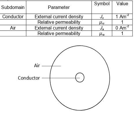
The proposed calculation of inductance in transmission line using FEA method in this work is solved with COMSOL Multiphysics software. Fig. 3 shows a two-dimensional (2D) model geometry that has been developed using finite element analysis (FEA) method to solve the magnetic field problem in transmission lines. The model geometry consists of a conductor (radius r) carrying a current perpendicular to the plane enclosed by surrounding air.
[image:2.595.345.501.63.321.2]
Fig.2. Three-phase double-circuit lines; (a) a transmission line tower and (b) model of the conductors
The partial differential equation (PDE) which is used to solve the magnetic field problem in the model is
(9)
A
/
0
r
J
ewhere μ0 is the vacuum permeability, μr is the relative
permeability (in Hm-1), A is the magnetic potential or the flux-linkage (Wbm-1) and J
e is the current density (Am-2).
[image:2.595.65.276.70.283.2]Free triangular mesh elements are used since it allows more freedom of meshing [9]. For a higher accuracy in the calculation, the mesh is refined near the conductor region. The subdomain settings of the model are detailed in Table 1.
Table I. Subdomain settings in the model geometry for magnetic field problem
Subdomain Parameter Symbol Value
Conductor External current density Jc 1 Am-2
Relative permeability μrc 1
Air External current density Ja 0 Am-2
Relative permeability μra 1
Fig.3. 2D model geometry of a single conductor
From the FEA model, the inductance, L between two points, p1 and p2 external to a conductor is obtained using
Air
[image:2.595.309.541.511.713.2]flux-linkage, λ divided by the current I through the conductor,
(10) p
c c
p
B
dl
J
S
I
L
21
/
where Jc is the current density across the cross-sectional
area, Sc of the conductor. The flux linkage, λ is obtained by
[image:3.595.306.530.161.252.2]integration of the magnetic flux density, B along a line connecting the two points.
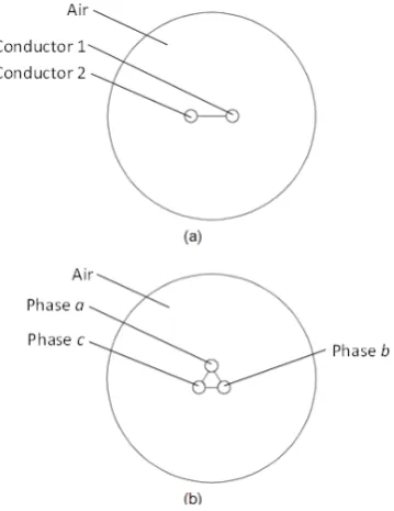
Fig.4. 2D model geometry of (a) two and (b) three conductors
Fig. 4a shows 2D FEA geometry of two conductors carrying current density Jc and -Jc while Fig. 4b shows three
conductors carrying current densities of Jc, Jc∟1200 and Jc∟2400. The flux linkage between two conductors, λ is
obtained by integration of the magnetic flux density, B along a line connecting the two conductors. For Fig. 4a, the inductance per unit length has been found to be equal to
(11)
2 2 1 1 2 1 2
1 12 2 1 12 2 1 12 c c c c c
c cc
ave
J
S
J
S
dl
B
I
L
where Iave is the average current of the two conductors, c1 and c2 and λ12 is the integration of the magnetic field, Bc1c2 along the line between the two conductors. It is multiplied by ½ since λ12 is the net flux-linkage due to two conductors.
For three conductors or three-phase transmission line, as shown in Fig. 4b, the inductance of phases a, b and c in the FEA model can be calculated using
(12)
L
a
12
L
ab
L
ac
,
L
b
12
L
ab
L
bc
,
L
c
12
L
ac
L
bc
where Lab, Lac and Lbc are the inductance due to flux-linkage
between phases a and b, a and c and b and c which are calculated using eq. (11). The inductance per phase per unit length has been found to be equal to the average of inductances from each conductor phase, where
(13)
L
13
L
a
L
b
L
c
Inserting eq. (12) into eq. (13), the inductance per phase per unit length can be written as a summation of inductances between different combination of two
conductors divided by the number of different combination of two conductors,
(14)
L
13
L
ab
L
ac
L
bc
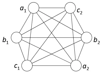
[image:3.595.85.265.170.403.2]To further verify eq. (14), the similar method is tested on a three-phase double-circuit transmission line, as shown in Fig. 5. The line between two phase conductors is used to calculate the flux-linkage between the two conductors. The inductance from each conductor phase is equal to
(15)
21 22 21 2 2 21
5 1 2 2 1 2 1 1 1 2 1 1 1 5 1 1 1 2 2 2 1 2 2 2 1 2 5 1 2 2 1 2 1 1 1 2 1 1 1 5 1 1 1 2 2 2 1 2 2 2 1 2 5 1 2 2 1 2 1 1 1 2 1 1 1 5 1 1 a c a c c c b c b c c a c c c a c b c b c c b b c b c b a b a b b a b c b c b b b a b b a a c a c a b a b a a a a c a c a b a b a a
L
L
L
L
L
L
L
L
L
L
L
L
L
L
L
L
L
L
L
L
L
L
L
L
L
L
L
L
L
L
L
L
L
L
L
L
Deriving the inductance per phase per unit length as the average of inductances from each conductor phase, again it is found that the inductance per phase per unit length equals to the summation of inductances between different combinations of two conductors, divided by the number of different combination of two conductors, where
(16)
2 1 2 2 1 2 2 1 1 1 2 1 2 2 1 2 2 2 1 2 2 1 2 1 1 1 2 1 1 1 15 1 2 1 2 1 2 1 6 1 c c c b c b c b c b b b c a c a b a b a a a c a c a b a b a c c b b a aL
L
L
L
L
L
L
L
L
L
L
L
L
L
L
L
L
L
L
L
L
L
Therefore, using flux-linkage method in finite element analysis, the inductance per phase per unit length can be deduced in general as the average of the inductances between different combinations of two conductors, Lij, or
(17)
L
j
i
n
n
L
n j i ij
,
)
1
(
2
1 , 1where i and j are the i-th and j-th conductor and n is the total number of conductors. The number of different combinations of two conductors equals to [n(n-1)]/2. Lij is
calculated using eq. (11). Eq. (17) can be used in general for n number of conductors in transmission lines.
Proposed Electric Potential FEA Method to Calculate the Capacitance
The partial differential equation (PDE) which is used to solve the electric field problem in the model is
(18)
(
E
)
where ε is the permittivity, E is the electric field and ρ is the charge density.
The charge in a conductor per unit length and time can be related to the current density, Jc on the cross-sectional
area of the conductor, S by
(19)
S
J
cSt
For per unit length and time, ρ equals to Jc in eq. (19).
Table II details the subdomain setting to compute the electric field in the model.
[image:3.595.312.540.327.389.2]divided by the electric potential, V12 between the two points from the FEA model,
(20)
21 12
/
pp
c
S
E
dl
V
q
C
where E is the electric field. V12 is obtained by integration of E along the line between the two points.
For two conductors in parallel to each other as in Fig. 4a, the capacitance per unit length is calculated as the average of charge in conductors 1 and 2 divided by the electric potential between the two conductors,
(21)
2 1 2 2 1 1 2 1 12 12 p p c cdl
E
S
J
S
J
V
q
C
where Jc1 and Jc2 are the current density in conductors 1 and 2.
In Fig. 4b, for a three-phase transmission line, the capacitance of phases a, b and c in the FEA model can be calculated using
(22)
ab ac
b
ab bc
c
ac bc
a
C
C
C
C
C
C
C
C
C
12
,
12
,
12
where Cab, Cac and Cbc are the capacitance between
phases a and b, a and c and b and c which are calculated using (21). The capacitance per phase per unit length has been found to be equal to the average of capacitances from each conductor phase, where
(23)
C
13
C
a
C
b
C
c
By inserting eq. (22) into eq. (23), the capacitance per phase per unit length equals to a summation of capacitances between different combination of two conductors divided by the number of different combination of two conductors, where
(24)
C
13
C
ab
C
ac
C
bc
Similar to the inductance calculation, eq. (24) is further verified on a three-phase double-circuit transmission line, as shown in Fig. 5. The capacitance from each conductor phase is equal to
(25)
21 2 2 21 22 21
5 1 2 2 1 2 1 1 1 2 1 1 1 5 1 1 1 2 2 2 1 2 2 2 1 2 5 1 2 2 1 2 1 1 1 2 1 1 1 5 1 1 1 2 2 2 1 2 2 2 1 2 5 1 2 2 1 2 1 1 1 2 1 1 1 5 1 1 a c a c c c b c b c c a c c c a c b c b c c b b c b c b a b a b b a b c b c b b b a b b a a c a c a b a b a a a a c a c a b a b a a
C
C
C
C
C
C
C
C
C
C
C
C
C
C
C
C
C
C
C
C
C
C
C
C
C
C
C
C
C
C
C
C
C
C
C
C
[image:4.595.330.504.59.190.2]The capacitance per phase per unit length has been found to be equals to a summation of capacitances between different combinations of two conductors, divided by the number of different combination of two conductors, where (26)
2 1 2 2 1 2 2 1 1 1 2 1 2 2 1 2 2 2 1 2 2 1 2 1 1 1 2 1 1 1 15 1 2 1 2 1 2 1 6 1 c c c b c b c b c b b b c a c a b a b a a a c a c a b a b a c c b b a aC
C
C
C
C
C
C
C
C
C
C
C
C
C
C
C
C
C
C
C
C
C
Fig.5. Three-phase double-circuit transmission lines
Table 2. Subdomain Settings in the Model Geometry for Electric Field Problem
Subdomain Parameter Symbol Value
Conductor Space charge density ρc Jc Cm-2
Relative permittivity εrc 1
Air Space charge density ρa 0 Cm-2
Relative permittivity εra 1
Therefore, the general equation of capacitance per phase per unit length in transmission lines for n conductors using FEA method can be written as
(27)
C
j
i
n
n
C
n j i ij
,
)
1
(
2
1 , 1where i and j are the i-th and j-th conductor and Cij is
[image:4.595.305.537.434.559.2]calculated using eq. (20). Eq. (27) is in similar pattern to that of the general equation for inductance as eq. (17).
Table 3. Comparison of inductance between two points external to a single conductor between the proposed and analytical methods
Distance between
two points (m) Analytical method (mH/km) [1] method (mH/km)Proposed FEA
5 1.1624 1.1624
10 1.3008 1.3008
15 1.3818 1.3818
20 1.4392 1.4392
25 1.4838 1.4838
30 1.5203 1.5203
35 1.5511 1.5511
40 1.5778 1.5778
45 1.6013 1.6013
Results and Discussion
a) Single conductor
Table 3 compares the inductance between two points external to a current-carrying conductor (radius of 0.015 m) obtained using the proposed flux-linkage FEA method and the analytical method. The inductance is higher when the distance between two points external to the conductor is larger. This is due to the inductance is dependent on flux-linkage between the two points, where a further distance yields higher inductance. The inductance is approaching constant values for a longer distance between the two points because the magnetic fields are nearly zero. For the inductance calculation, there is a good agreement between results obtained using the proposed flux-linkage FEA method and the analytical method. Therefore, this shows that the proposed FEA method can be used to calculate inductance between two points external to a current-carrying conductor.
The capacitance between two points external to a current-carrying conductor (radius of 0.015 m) obtained
using the proposed electric potential FEA method and the analytical method is shown in Table 4. The capacitance between the two points decreases with their spacing because the potential different between them increases. From this table, the results obtained using the proposed FEA method and analytical method is in good agreement. Hence, the proposed FEA method can also be used to calculate the capacitance between two points external to a current-carrying conductor.
Table 4. Comparison of capacitance between two points external to a single conductor between the proposed and analytical methods
Distance between two points (m)
Analytical method (pF/m) [1]
Proposed FEA method (pF/m)
5 9.7345 11.0619
10 8.8496 9.7345 15 8.4071 9.2921 20 7.9646 8.8496 25 7.7434 8.8493 30 7.5221 8.8490 35 7.5218 8.8488 40 7.5215 8.8485 45 7.5211 8.8482
b) Two conductors
Comparison between values obtained using the proposed FEA and analytical methods of inductance as a function of distance between centres of two current-carrying conductors (radius of 0.015 m each) is shown in Table 5. Similar to a single current-carrying conductor, the inductance increases when the spacing between the two conductors is larger. The inductance calculated using the proposed method agrees with the analytical method. This again shows that the proposed FEA method can be used to calculate inductance between two current-carrying conductors.
Table 5. Comparison of inductance for different distance between two conductors between the proposed and analytical methods
Distance between two conductors (m)
Analytical method (mH/km) [1]
Proposed FEA method (mH/km)
10 1.3505 1.3462 20 1.4891 1.4730 30 1.5702 1.5340 40 1.6277 1.5631 50 1.6723 1.6472 60 1.7088 1.6642 70 1.7396 1.6787 80 1.7663 1.6863
Table 6. Comparison of capacitance for different distance between two conductors between the proposed and analytical methods
Distance between two conductors (m)
Analytical method (pF/m) [1]
Proposed FEA method (pF/m)
10 4.2668 4.2667
20 3.8858 3.8857
30 3.6572 3.6571
40 3.1238 3.0857
50 3.4286 3.3905
60 3.4284 3.3903
70 3.4282 3.3901
80 3.4281 3.3900
c) Three conductors or three-phase transmission line
Table 6 shows comparison between capacitance obtained from the proposed FEA and analytical methods for different distance between centres of two current-carrying conductors (radius of 0.015 m each). It can be seen that both methods are in good agreement. Therefore, the proposed electric potential FEA method can be used to
calculate the capacitance between two current-carrying conductors in a transmission line.
The proposed method has also been used to calculate the inductance of a three-phase transmission line, consisting of three conductors (radius of 0.015 m each) arranged symmetrically. Referring to Table 7, the inductance values calculated using the proposed FEA method seems to be in agreement with the values calculated using the analytical method. The behaviour of inductance as a function of spacing between three conductors is similar to a two-conductor transmission line.
The results of capacitance per phase per unit length using the proposed FEA and analytical methods for a three-phase transmission line are shown in Table 8. This again shows the calculated capacitance values using the proposed FEA method are in good agreement with the analytical method.
Table 7. Comparison of inductance for different distance between three phase conductors between the proposed and analytical methods
Distance between two conductors (m)
Analytical method (mH/km) [1]
Proposed FEA method (mH/km)
10 1.3505 1.3152
20 1.4891 1.4415
30 1.5702 1.4987
40 1.6277 1.5140
50 1.6723 1.4743
60 1.7088 1.6373
70 1.7396 1.6320
80 1.7663 1.6235
Table 8. Comparison of capacitance for different distance between three phase conductors between the proposed and analytical methods
Distance between two conductors (m)
Analytical method (pF/m) [1]
Proposed FEA method (pF/m)
10 4.2593 4.3519
20 3.8889 3.9815
30 3.6111 3.7037
40 3.5185 3.6111
50 3.4259 3.4260
60 3.4257 3.4258
70 3.4256 3.4257
80 3.4255 3.4256
Table 9. Calculated Inductance for Three-Phase Double-Circuit Lines
Parameters Analytical
method (mH/km) [1]
Proposed FEA method (mH/km) x1, m x2, m x3, m ym 1, y2, m
5.5 8.25 6.25 3.5 3.25 0.5692 0.5687 8.25 12.375 9.375 5.25 4.875 0.6097 0.6076
11.0 16.5 12.5 7.0 6.5 0.6385 0.6321
13.75 20.625 15.625 8.75 8.125 0.6608 0.6452 Table 10. Calculated capacitance for three-phase double-circuit lines
Parameters Analytical
method (pF/m) [1]
Propose d FEA method
(pF/m) x1, m x2, m x3, m y1,
m
y2, m
5.5 8.25 6.25 3.5 3.25 10.219 9.8289 8.25 12.375 9.375 5.25 4.875 9.5102 9.1442
11.0 16.5 12.5 7.0 6.5 9.0642 8.6711
13.75 20.625 15.625 8.75 8.125 8.7461 8.2617
d) Three-phase double-circuit transmission line
calculation is 0.015 m. It has been found that the inductance values calculated using all methods are within reasonable agreement to each other. Therefore, the proposed FEA method can be said reasonable in calculating the inductance of three-phase double-circuit transmission lines.
Table 10 shows the calculated capacitance using the proposed FEA and analytical methods for a three-phase double-circuit line with model parameters similar to those that have been used in Table 9. The results clearly show that the values calculated using both methods are within reasonable agreement to each other. Thus, the proposed FEA method is acceptable for capacitance calculation of a three-phase double-circuit transmission line.
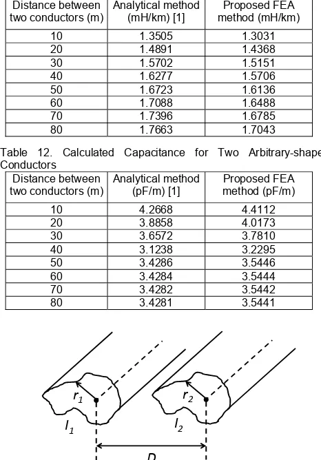
Table 11. Calculated Inductance for Two Arbitrary-shaped Conductors
Distance between two conductors (m)
Analytical method (mH/km) [1]
Proposed FEA method (mH/km)
10 1.3505 1.3031
20 1.4891 1.4368
30 1.5702 1.5151
40 1.6277 1.5706
50 1.6723 1.6136
60 1.7088 1.6488
70 1.7396 1.6785
[image:6.595.51.284.226.560.2]80 1.7663 1.7043
Table 12. Calculated Capacitance for Two Arbitrary-shaped Conductors
Distance between two conductors (m)
Analytical method (pF/m) [1]
Proposed FEA method (pF/m)
10 4.2668 4.4112
20 3.8858 4.0173
30 3.6572 3.7810
40 3.1238 3.2295
50 3.4286 3.5446
60 3.4284 3.5444
70 3.4282 3.5442
80 3.4281 3.5441
e) Inductance and capacitance for arbitrary conductor shape
Fig. 6 shows two conductors of arbitrary shape with a cross sectional area of A1 and A2, carrying a current, I1 and I2, separated by a distance D. For the calculation of inductance and capacitance, the analytical method assumes that the conductor is a cylindrical shape with a radius of r, as shown in eqs. (3) and (4). Thus, this is the limitation of the analytical method as it is not applicable to general conductor shape in transmission lines [10]. In Fig. 6, if the radius of each conductor is taken as the average radius (here, the average radius equals to 0.015 m), if r1 = r2 and I2 = -I1, the calculated inductance and capacitance using the proposed FEA and analytical method are shown in Tables 11 and 12. The parameters used are the same as in Tables 1 and 2. From these tables, it is found that the results are slightly different between the two methods, unlike those obtained in Tables 5 and 6. This may be due to
the analytical method assumes that the conductor is a cylindrical, which simplifies the calculation. Whereas, the inductance and capacitance calculated using the FEA method depend on the shape of the conductor, which influences the magnetic and electric field distributions around the conductor.
Conclusions
Calculations of the inductance using magnetic flux-linkage and the capacitance using electric potential in finite element analysis (FEA) method for various transmission line configurations have been proposed in this work. The inductance and capacitance calculated using the proposed FEA method has been validated through comparison with the analytical method. It has been found that both results from the proposed FEA and analytical methods are within reasonable agreement to each other. From the FEA model, general equations of inductance and capacitance per phase per unit length for multi-conductors in power system transmission lines have been deduced as the summation of the inductances and capacitances between two conductors divided by the number of different combinations of two conductors respectively. The calculations of inductance and capacitance using the proposed FEA method are simple, straight forward and is applicable in general, especially for complicated conductor arrangements and arbitrary conductor shapes.
This work was supported by University of Malaya, Malaysia through UMRG Research Grant (Grant no. RG135/11AET).
REFERENCES
[1] H. Saadat, Power System Analysis, 2nd ed.: McGraw-Hill (2004).
[2] S. Cristina, M. Feliziani, A finite element technique for multiconductor cable parameters calculation, IEEE T. Magn. 25 (1989) 2986-2988.
[3] S. M. Musa, M. N. O. Sadiku, Application of the finite element method in calculating the capacitance and inductance of multiconductor transmission lines, IEEE Southeastcon. (2008) 300-304.
[4] R. Escarela-Perez, E. Campero-Littlewood, M. A. Arjona-Lopez, A. Laureano-Cruces, Comparison of two techniques for two-dimensional finite-element inductance computation of electrical machines, IEE Proc. - Electric Power Applications. 152 (2005) 855-861.
[5] E. Melgoza, R. Escarela-Perez, J. Alvarez-Ramirez, Finite-Element Inductance Computation in 2-D Eddy-Current Systems Using Sensitivity Analysis, IEEE T. Energy Conver. 25 (2010) 690-697.
[6] J. D. Glover, M. S. Sarma, T. J. Overbye, Power System Analysis and Design, 4th ed.: Cengage Learning, USA (2004). [7] D. Labridis, V. Hatziathanassiou, Finite element computation
of field, forces and inductances in underground SF6 insulated cables using a coupled magneto-thermal formulation, IEEE T. Magn. 30 (1994) 1407-1415.
[8] R. Lucas, S. Talukdar, Advances in Finite Element Techniques for Calculating Cable Resistances and Inductances, IEEE T. Power Ap. Syst. PAS-97 (1978) 875-883.
Authors: dr. Hazlee Azil Illias, Department of Electrical Engineering, Faculty of Engineering, University of Malaya, 50603 Kuala Lumpur, Malaysia, E-mail: [email protected]; dr. Ab Halim Abu Bakar, University of Malaya Power Energy Dedicated Advanced Centre (UMPEDAC), University of Malaya, 50603 Kuala Lumpur, Malaysia, E-mail: [email protected]; dr. Hazlie Mokhlis, Department of Electrical Engineering, Faculty of Engineering, University of Malaya, 50603 Kuala Lumpur, Malaysia, E-mail: [email protected]; ms. Syahirah Abd Halim, Department of Electrical Engineering, Faculty of Engineering, University of Malaya, 50603 Kuala Lumpur, Malaysia, E-mail: [email protected].