Technology (IJRASET)
Performance Comparison of a Speed Controlled
PFC Bridgeless Buck-Boost Converter fed BLDC
Motor Drive with PI &Fuzzy Controllers
B. Gopala Krishna1, Dr. M. Uma Vani2
1
PG Scholar, 2Professor and Head, Department of EEE Lakkireddy Balireddy College of Engineering, MYVALARAM
Abstract—This paper presents a power factor corrected (PFC) bridgeless (BL) buck–boost converter-fed brushless direct current (BLDC) motor drive as a cost-effective solution for low-power applications. An approach of speed control of the BLDC motor by controlling the dc link voltage of the voltage source inverter (VSI) is used with a single voltage sensor. This facilitates the operation of VSI at fundamental frequency switching by using the electronic commutation of the BLDC motor which offers reduced switching losses. A BL configuration of the buck–boost converter is proposed which offers the elimination of the diode bridge rectifier, thus reducing the conduction losses associated with it. A PFC BL buck–boost converter is designed to operate in discontinuous inductor current mode (DICM) to provide an inherent PFC at ac mains. . In this work, conventional PI and fuzzy logic controllers have been used for the speed control of BLDC motor drive. The performance of conventional PI and Fuzzy controllers are compared under variable reference speed and varying supply voltages with improved power quality at ac mains. The obtained power quality indices are within the acceptable limits of international power quality standards such as the IEC 61000-3-2. The performance of the proposed drive is simulated in MATLAB/Simulink environment
Keywords— Bridgeless (BL) buck–boost converter, brushless direct current (BLDC) motor, discontinuous inductor current mode (DICM), power factor corrected (PFC), power quality.
I. INTRODUCTION
Efficiency and cost are the major concerns in the development of low-power motor drives targeting household applications such as fans, water pumps, blowers, mixers, etc. [1], [2]. The use of the brushless direct current (BLDC) motor in these applications is becoming very common due to features of high efficiency, high flux density per unit volume, low maintenance requirements, and low electromagnetic-interference problems [1]. These BLDC motors are not limited to household applications, but these are suitable for other applications such as medical equipment, transportation, HVAC, motion control, and many industrial tools [2]–[4].
A BLDC motor has three phase windings on the stator and permanent magnets on the rotor [5], [6]. The BLDC motor is also known as an electronically commutated motor because an electronic commutation based on rotor position is used rather than a mechanical commutation which has disadvantages like sparking and wear and tear of brushes and commutator assembly [5], [6]. Power quality problems have become important issues to be considered due to the recommended limits of harmonics in supply current by various international power quality standards such as the International Electrotechnical Commission (IEC)61000-3-2 [7]. A BLDC motor when fed by a diode bridge rectifier (DBR) with a high value of dc link capacitor draws peak current which can lead to a THD of supply current of the order of 65% and power factor as low as 0.8 [8]. Hence, a DBR followed by a power factor corrected (PFC) converter is utilized for improving the power quality at ac mains. Many topologies of the single-stage PFC converter are reported in the literature which has gained importance because of high efficiency as compared to two-stage PFC converters due to low component count and a single switch for dc link voltage control and PFC operation [9], [10].
Technology (IJRASET)
converter can be designed in either continuous conduction mode (CCM) or in discontinuous conduction mode (DCM)[7].The voltage stress in continuous conduction mode is less than the voltage stress in discontinuous conduction mode. But continuous conduction mode requires the study of two control loops (Voltage and current loop) which is not a cost effective solution and may also cause imbalance in the reading due to different sensitivities of the sensors. On the other hand, Discontinuous mode of conduction requires only a single sensor for the speed control purpose. This eliminates the problem of different current sensitivity and reduces the cost of the system also. But DCM of conduction lead a high voltage stress at the switches so this mode of conduction is used mainly for low power household applications such as fan load, driers, mixer etc[8].
This paper presents a BL buck–boost converter-fed BLDC motor drive with variable dc link voltage of VSI for improved power quality at ac mains with reduced components. Fuzzy logic controller (FLC) is the most useful technology for control applications of motor drives as FLC can handle non-linearity, load disturbance and parametric variations[9]. Due to these reasons ,for the speed control of BLDC motor a fuzzy logic controller has been used and its performance is compared with conventional PI controller..Power factor and total harmonic distortion (THD) has been evaluated at variable speed and supply voltages [10]. A MATLAB/simulink model has been used to verify the performance of this bridgeless converter fed BLDC motor drive with conventional PI and fuzzy logic controllers.
II. PROPOSED PFC BL BUCK –BOOST CONVERTER-FED BLDC MOTOR DRIVE
Fig. 1. Proposed BLDC motor drive with front-end BL buck–boost converter
[image:3.612.111.520.311.649.2]Technology (IJRASET)
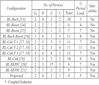
Table 1: Comparative analysis of proposed bl buck –boost converter With existing topologies
control of VSI using a BL buck–boost converter. This reduces the switching losses in VSI due to the low frequency operation of VSI for the electronic commutation of the BLDC motor. The performance of the proposed drive is evaluated for a wide range of speed control with improved power quality at ac mains. Moreover, the effect of supply voltage variation at ac mains is also studied to demonstrate the performance of the drive in practical supply conditions. Voltage and current stresses on the PFC converter switch are also evaluated for determining the switch rating and heat sink design A brief comparison of various configurations reported in the literature is tabulated in Table I. The comparison is carried out on the basis of the total number of components (switch—Sw , diode—D, inductor—L, and capacitor—C) and total number of components conducting during each
half cycle of supply voltage. The BL buck [13] and boost [14], [15] converter configurations are not suitable for the required application due to the requirement of high voltage conversion ratio.
The proposed configuration of the BL buck–boost converter has the minimum number of components and least number of conduction devices during each half cycle of supply voltage which governs the choice of the BL buck–boost converter for this application.
III. OPERATION OF PROPOSED SYSTEM
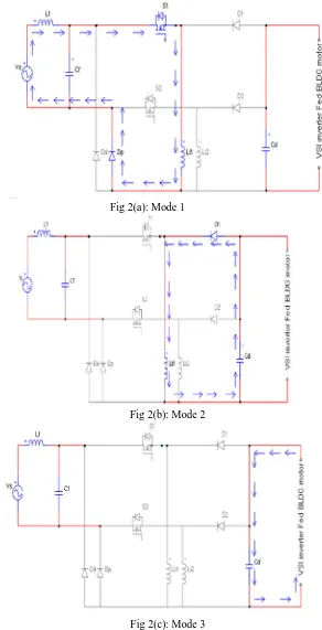
The operation of the PFC BL buck–boost converter is classified into two parts which include the operation during the positive and negative half cycles of supply voltage and during the complete switching cycle.
A. Operation in positive half cycle
Mode 1: As shown in figure 2(a) in mode 1, switch S1 conducts when gate pulse is applied to it. Magnetizing current flow from S1 -L1-Dp-source .Due to this current inductor L1 charges and initial charge stored by the DC link capacitor gets discharges by the BLDC Motor Drive.
Mode 2: In this mode switch S1 is turned off and total energy stored in the inductor is transferred to the DC link capacitor. Now inductor energy reduces to zero and Cd charges completely. This is shown in figure 2(b)
Technology (IJRASET)
Fig 2(a): Mode 1
Fig 2(b): Mode 2
Fig 2(c): Mode 3
B. Operation in complete half cycle
Mode 1: As shown in figure 2(d), in negative half cycle switch S2-D2-L2 and Dn completes the path. At first when switch S2 is triggered then magnetizing current flows from S1- L1-Dn-source.This magnetizing current leads to store an energy in the inductor L2 and initial charge stored by the DC link capacitor gets discharges by the BLDC Motor Drive.
[image:5.612.173.465.85.656.2]Technology (IJRASET)
inductor energy reduces to zero and Cd charges completely. This is shown in figure 2(e).
Mode 3: Now inductor falls into discontinuous mode of conduction. Energy across the inductor is zero so there is no more charging of DC link capacitor. Now DC link capacitor start discharging by the VSI fed BLDC Motor Drive. Now Cd starts decreasing and this process repeats itself when switch S2 is triggered again.
Fig 2(d): Mode1
Fig 2(e):Mode 2
[image:6.612.165.453.136.699.2]Technology (IJRASET)
IV. CONTROL OF PFC BL BUCK –BOOST CONVERTER-FED BLDC MOTOR DRIVE
A. Control of Front-End PFC Converter: Voltage Follower Approach
The control of the front-end PFC converter generates the PWM pulses for the PFC converter switches (Sw1 and Sw2) for dc link voltage control with PFC operation at ac mains. A single voltage control loop (voltage follower approach) is utilized for the PFC BL buck–boost converter operating in DICM. A reference dc link voltage ( ∗)
is generated as
∗= ∗... (1)
where and ∗ are the motor’s voltage constant and the reference speed, respectively The voltage error signal ( ) is generated by comparing the reference dc link voltage ( ∗)
with the sensed dc link voltage ( ) as (K) = ∗(K)− (k)………. .. (2)
where k represents the kth sampling instant. This error voltage signal ( ) is given to the voltage proportional–integral (PI) controller to generate a controlled output voltage ( ) as
(K) = ( −1) + { ( )− ( −1)} + ( )…..(3) where kp and ki are the proportional and integral gains of the voltage PI controller.
Finally, the output of the voltage controller is compared with a high frequency sawtooth signal (md) to generate the PWM pulses as For > 0; if < then S = ON
if > then S = OFF ……… (4)
For < 0; if < then S = ON
if ≥ then S = OFF ……….(5)
where Sw1 and Sw2 represent the switching signals to the switches of the PFC converter.
B. Control of BLDC Motor: Electronic Commutation
An electronic commutation of the BLDC motor includes the proper switching of VSI in such a way that a symmetrical dc current is drawn from the dc link capacitor for 120°. And placed symmetrically at the center of each phase. A Hall-effect position sensor is
used to sense the rotor position on a span of 60°., which is required for the electronic commutation of the BLDC motor. The
[image:7.612.117.500.493.703.2]conduction states of two switches (S1 and S4) are shown in Fig. 3. A line current is drawn from the dc link capacitor whose magnitude depends on the applied dc link voltage ( ), back electromotive forces (EMFs) ( and ), resistances ( and ), and self-inductance and mutual inductance ( , , and M) of the stator windings. Table II shows the different switching states of the VSI feeding a BLDC motor based on the Hall-effect position signals (Ha . Hc).
Technology (IJRASET)
Table 2: Switching States for Achieving Electronic Commutation of BLDC Motor Based on Hall-Effect Position Signals
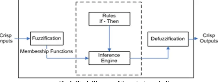
C. Proposed Fuzzy Logic Controller
[image:8.612.116.469.364.496.2]The control framework is in light of fuzzy logic. FL controller is an one –sort, non- straight controller and programmed. This kind of the control drawing closer to human thinking that makes the utilization of the acknowledgement, vulnerability, imprecision and fluffiness in the choice making procedure, figures out how to offer an exceptionally tasteful execution, without the need of a definite numerical model of the framework, just by fusing the specialists' learning into the Fluffy.
Fig 4: Block Diagram of fuzzy logic controller
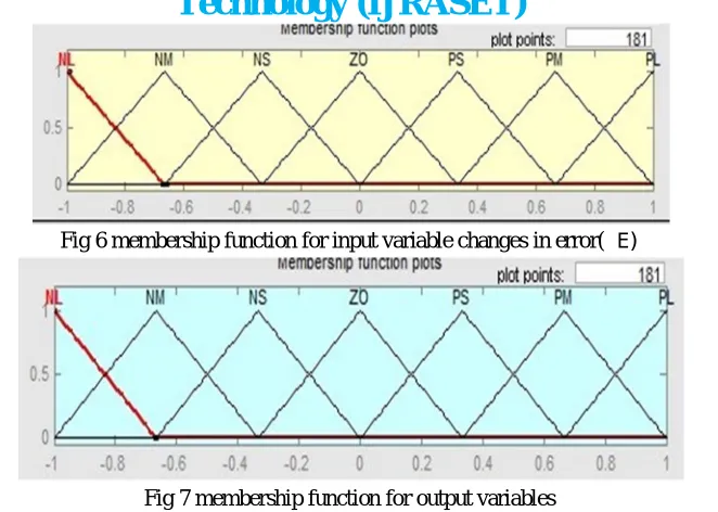
[image:8.612.154.453.573.711.2]For the best control performance and simplicity,triangular membership functions are used as the input and output for FLC. The inputs of the fuzzy controller are expressed in several linguistic levels.These levels has been described as Positive large(PL), Positive medium(PM),Positive small(PS),Zero order(ZO), Negative large(NL), Negative medium(NM), Negative small(NS). Figures 5-7 respectively shows membership functions of the input signal (e1),change in input signal (e2) and output torque (Te).
Technology (IJRASET)
Fig 6 membership function for input variable changes in error(∆E)
Fig 7 membership function for output variables
Table 3 shows the rule base used in this work which is based on the fuzzy variables selected and the observations of human operator to ensure the stability and steady state accuracy.
Table 3:Fuzzy rule base E/∆E
Type equation here.
NL NM NS ZO PS PM PL NL NL NL NL NM NS ZO PS NM NL NL NL NM NS ZO PS NS NL NL NM NS ZO PS PM
ZO NL NM NS ZO PS PM PL PS NM NS ZO PS PM PL PL PM NS ZO PS PM PL PL PL PL ZO PS PM PL PL PL PL
V. MATLAB/SIMULINK RESULTS
A. Test system data
No of poles(P)=4 Ra = 0.2 Ω
La = 8.5 mH
Ke = 146.077 V,peak L-L/Krpm Kt = 1.4 N.m/A Peak
J = 1.3× 10 N.m/ B = 0.005 N.m.s Controller Gains: Kp = 0.4
Ki = 3
B. Steady state results of PI controlled drive rated 200 volts
Technology (IJRASET)
Fig 8: Steady state results of PI controlled drive at rated 200 volts
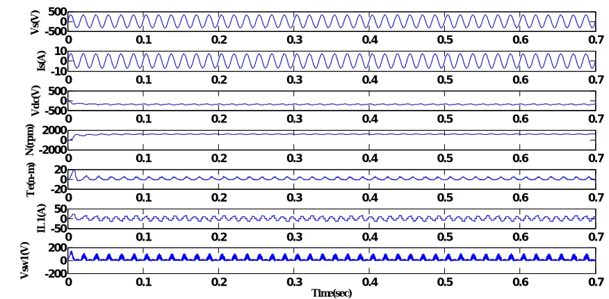
1) Steady state results of FUZZY controlled drive rated 200 volts: The steady-state behavior of the proposed BLDC motor drive for two cycles of supply voltage at rated condition (rated dc link voltage of 200 V) is shown in Fig. 9. The performance of the proposed BLDC motor drive for speed control by using fuzzy controller has been shown and oscillations in speed troque are reduced compared with the PI controller.
Fig 9:Steady state results of FUZZY controlled drive at rated 200 volts
0
0.1
0.2
0.3
0.4
0.5
0.6
0.7
-500
0
500
V s( V )0
0.1
0.2
0.3
0.4
0.5
0.6
0.7
-10
0
10
Is
(A
)
0
0.1
0.2
0.3
0.4
0.5
0.6
0.7
-500
0
500
V d c( V0
0.1
0.2
0.3
0.4
0.5
0.6
0.7
-2000
0
2000
N (r p m )0
0.1
0.2
0.3
0.4
0.5
0.6
0.7
-20
0
20
T e( N -M )0
0.1
0.2
0.3
0.4
0.5
0.6
0.7
-50
0
50
IL 1 (A )0
0.1
0.2
0.3
0.4
0.5
0.6
0.7
-200
0
200
Time(sec) V sw 1 (V )0 0.1 0.2 0.3 0.4 0.5 0.6 0.7
-5000 500 V s( V )
0 0.1 0.2 0.3 0.4 0.5 0.6 0.7
-100
10
Is
(A
)
0 0.1 0.2 0.3 0.4 0.5 0.6 0.7
-5000 500 V d c( V )
0 0.1 0.2 0.3 0.4 0.5 0.6 0.7
-20000 2000 N (r p m )
0 0.1 0.2 0.3 0.4 0.5 0.6 0.7
-200 20 T e( n -m )
0 0.1 0.2 0.3 0.4 0.5 0.6 0.7
-500 50 IL 1 (A )
0 0.1 0.2 0.3 0.4 0.5 0.6 0.7
[image:10.612.76.514.493.708.2]Technology (IJRASET)
[image:11.612.93.520.118.346.2]2) THD analysis results of source current with PI controller at rated 200 volts: The harmonic spectra of the supply current at rated dc link voltage of 200V and peak value of 5amps are shown in fig 10 for PI controller, respectively, which shows that the THD of supply current obtained is under the acceptable limits of IEC 61000-3-2.
Fig 10:THD analysis results of source current with PI controller at rated 200 volts
3) THD analysis results of source current with FUZZY controller at rated 200 volts: The harmonic spectra of the supply current at rated dc link voltage of 200V and peak value of 5amps are shown in Fig 11 for fuzzy controller respectively, which shows that the THD of supply current obtained is under the acceptable limits of IEC 61000-3-2 and improved as compared with PI controller.
Fig11THD: analysis results of source current with FUZZY controller at rated 200 volts
0.5 0.502 0.504 0.506 0.508 0.51 0.512 0.514 0.516 0.518 -5
0 5
FFT window: 1 of 35 cycles of selected signal
Time (s)
0 200 400 600 800 1000 1200 1400 1600 1800 2000
0 5 10 15 20 25 30 Frequency (Hz) Fundamental (50Hz) = 6.432 , THD= 6.73%
M a g ( % o f F u n d a m e n ta l)
0.5 0.502 0.504 0.506 0.508 0.51 0.512 0.514 0.516 0.518 -5
0 5
FFT window: 1 of 33 cycles of selected signal
Time (s)
0 100 200 300 400 500 600 700 800 900 1000
0 0.2 0.4 0.6 0.8 1 Frequency (Hz) Fundamental (50Hz) = 7.365 , THD= 2.00%
[image:11.612.96.514.425.700.2]Technology (IJRASET)
Table 4: Comparision of performances at 200 volts PARAMETER PI
CONTROLLER
FUZZY
CONTROLLER Vdc 200 200
Is 6 6
PF 0.98 0.92 THD 6.73 2
[image:12.612.105.508.241.465.2]C. Steady state results of PI controlled drive rated 185 volts: The steady-state behavior of the proposed BLDC motor drive for two cycles of supply voltage at rated condition (rated dc link voltage of 185 V) is shown in Fig.12. The performance of the proposed BLDC motor drive for speed control by using pi controller.
Fig 12:Steady state results of PI controlled drive at rated 185 volts
1) Steady state results of FUZZY controlled drive rated 185 volts: The steady-state behavior of the proposed BLDC motor drive for two cycles of supply voltage at rated condition (rated dc link voltage of 185 V) is shown in Fig.13 by using fuzzy controller. Oscillations in speed troque are reduced compared with the PI controller
Fig 13: Steady state results of FUZZY controlled drive at rated 185 volts
0 0.1 0.2 0.3 0.4 0.5 0.6 0.7
-5000 500 V s( V )
0 0.1 0.2 0.3 0.4 0.5 0.6 0.7
-100 10
Is
(A
)
0 0.1 0.2 0.3 0.4 0.5 0.6 0.7
-5000 500 V d c( V )
0 0.1 0.2 0.3 0.4 0.5 0.6 0.7
-20000 2000 N (r p m )
0 0.1 0.2 0.3 0.4 0.5 0.6 0.7
-100 10 T e( n -m )
0 0.1 0.2 0.3 0.4 0.5 0.6 0.7
-200 20 IL 1 (A )
0 0.1 0.2 0.3 0.4 0.5 0.6 0.7
-500 0 500 Time(sec) V s w 1 (V )
0 0.1 0.2 0.3 0.4 0.5 0.6 0.7
-5000 500 V s( V )
0 0.1 0.2 0.3 0.4 0.5 0.6 0.7
-100 10
Is
(A
)
0 0.1 0.2 0.3 0.4 0.5 0.6 0.7
-5000 500 V d c( V )
0 0.1 0.2 0.3 0.4 0.5 0.6 0.7
-10000 1000 N (r p m )
0 0.1 0.2 0.3 0.4 0.5 0.6 0.7
-1000 100 T e( n -m )
0 0.1 0.2 0.3 0.4 0.5 0.6 0.7
-500 50 IL 1 (A )
0 0.1 0.2 0.3 0.4 0.5 0.6 0.7
[image:12.612.103.503.548.706.2]Technology (IJRASET)
[image:13.612.82.530.117.344.2]2) THD analysis results of source current with PI controller at rated 185volts: The harmonic spectra of the supply current at rated dc link voltage of 185V and peak value of 5amps are shown in Fig 14 for PI controller, respectively, which shows that the THD of supply current obtained is under the acceptable limits of IEC 61000-3-2.
Fig 14:THD analysis results of source current with PI controller at rated 185volts
3) THD analysis results of source current with FUZZY controller at rated 185volts: The harmonic spectra of the supply current at rated dc link voltage of 200Vand peak value of 5amps are shown in Fig 15 for fuzzy controller respectively, which shows that the THD of supply current obtained is under the acceptable limits of IEC 61000-3-2 and improved compared with pi controller
Fig 15:THD analysis results of source current with FUZZY controller at rated 185volts
0.5 0.502 0.504 0.506 0.508 0.51 0.512 0.514 0.516 0.518
-5 0 5
FFT window: 1 of 35 cycles of selected signal
Time (s)
0 100 200 300 400 500 600 700 800 900 1000
0 5 10 15 20 25 30 Frequency (Hz) Fundamental (50Hz) = 6.432 , THD= 12.73%
M a g ( % o f F u n d a m e n ta l)
0.5 0.502 0.504 0.506 0.508 0.51 0.512 0.514 0.516 0.518
-5 0 5
FFT window: 1 of 33 cycles of selected signal
Time (s)
0 100 200 300 400 500 600 700 800 900 1000
0 0.2 0.4 0.6 0.8 1 Frequency (Hz) Fundamental (50Hz) = 7.365 , THD= 2.00%
[image:13.612.82.533.427.702.2]Technology (IJRASET)
Table 5: Comparison of performance at 185 volts PARAMETER PI controller Fuzzy controller
Vdc 185 185 Is 6.432 7.366 Pf 0.894 0.8674 THD 12 2
D. Steady state results of PI controlled drive at rated 130 volts
[image:14.612.96.513.244.449.2]The steady-state behavior of the proposed BLDC motor drive for two cycles of supply voltage at rated condition (rated dc link voltage of 130 V) is shown in Fig.16. The performance of the proposed BLDC motor drive for speed control by using pi controller has been shown
Fig 16: Steady state results of PI controlled drive at rated 130 volts
[image:14.612.106.502.542.705.2]1) Steady state results of FUZZY controlled drive at rated 130volts: The steady-state behavior of the proposed BLDC motor drive for two cycles of supply voltage at rated condition (rated dc link voltage of 130V) is shown in Fig.17. The performance of the proposed BLDC motor drive for speed control by using fuzzy controller has been shown and oscillations in speed troque are reduced compared with the PI controller.
Fig 17: Steady state results of FUZZY controlled drive at rated 130volts
0 0.1 0.2 0.3 0.4 0.5 0.6 0.7
-5000 500 V s( V )
0 0.1 0.2 0.3 0.4 0.5 0.6 0.7
-100
10
Is(
A
)
0 0.1 0.2 0.3 0.4 0.5 0.6 0.7
-5000 500 V d c( V )
0 0.1 0.2 0.3 0.4 0.5 0.6 0.7
-20000 2000 N (r p m )
0 0.1 0.2 0.3 0.4 0.5 0.6 0.7
-200 20 T e( n -m )
0 0.1 0.2 0.3 0.4 0.5 0.6 0.7
-500 50 IL 1 (A )
0 0.1 0.2 0.3 0.4 0.5 0.6 0.7
-200 0 200 Time(sec) V sw 1 (V )
0 0.1 0.2 0.3 0.4 0.5 0.6 0.7
-5000 500 V s( V )
0 0.1 0.2 0.3 0.4 0.5 0.6 0.7
-100 10
Is
(A
)
0 0.1 0.2 0.3 0.4 0.5 0.6 0.7
-2000 200 V d c( v )
0 0.1 0.2 0.3 0.4 0.5 0.6 0.7
-10000 1000 N (r p m )
0 0.1 0.2 0.3 0.4 0.5 0.6 0.7
0 50 100 T e( n -m )
0 0.1 0.2 0.3 0.4 0.5 0.6 0.7
-500 50 IL 1 (A )
0 0.1 0.2 0.3 0.4 0.5 0.6 0.7
Technology (IJRASET)
[image:15.612.81.536.117.374.2]2) THD analysis results of source current with PI controller at rated 130volts: The harmonic spectra of the supply current at rated dc link voltage of 130V and peak value of 5amps are shown in Fig 18 for PI controller, respectively, which shows that the THD of supply current obtained is under the acceptable limits of IEC 61000-3-2.
Fig 18:THD analysis results of source current with PI controller at rated 130volts
3) THD analysis results of source current with FUZZY controller at rated 130volts: The harmonic spectra of the supply current at rated dc link voltages of 130V and peak value of 5amps are shown in Fig 19 for fuzzy controller respectively, which shows that the THD of supply current obtained is under the acceptable limits of IEC 61000-3-2 and improved compared with pi controller results of Fig 18
Fig 19 :THD analysis results of source current with PI controller at rated 130volts
0.5 0.502 0.504 0.506 0.508 0.51 0.512 0.514 0.516 0.518
-200 0 200
FFT window: 1 of 35 cycles of selected signal
Time (s)
0 500 1000 1500
0 5 10 15 20 25 30 Frequency (Hz) Fundamental (50Hz) = 9.94 , THD= 16.73%
M a g ( % o f F u n d a m e n ta l)
0.5 0.502 0.504 0.506 0.508 0.51 0.512 0.514 0.516 0.518
-5 0 5
FFT window: 1 of 33 cycles of selected signal
Time (s)
0 100 200 300 400 500 600 700 800 900 1000
0 0.2 0.4 0.6 0.8 1 Frequency (Hz) Fundamental (50Hz) = 7.365 , THD= 3.50%
[image:15.612.87.530.451.703.2]Technology (IJRASET)
Table 6: Performance comparison
Parameter Pi controller Fuzzy controller Vdc 130 130
Is 9.94 7 PF 0.7 0.7049 THD 16.73 3.50
[image:16.612.100.515.192.288.2]The performance comprasion of the BLDC drive for speed control at different DC link voltages with PI and FUZZY logic controllers is shown in Table 7
Table 7: Overall performance comparison of BLDC drive S.NO PI CONTROLLER FUZZY CONTROLER
Vdc(Volts) N(rpm) Is(A) PF %THD N(rpm) Is(A) PF %THD 130 1000 9.94 0.7 15 850 7 0.70 3.50 185 1200 6.6 0.8 12 1000 7 0.86 2 200 1320 6 0.98 6.73 1200 6 0.92 2
VI. CONCLUSION
A PFC BL buck–boost converter-based VSI-fed BLDC motor drive has been proposed targeting low-power applications. A new method of speed control has been utilized by controlling the voltage at dc bus and operating the VSI at fundamental frequency for the electronic commutation of the BLDC motor for reducing the switching losses in VSI. The front-end BL buck–boost converter has been operated in DICM for achieving an inherent power factor correction at ac mains. A satisfactory performance has been achieved for speed control and supply voltage variation with power quality indices within the acceptable limits of IEC 61000-3-2. Moreover, voltage and current stresses on the PFC switch have been evaluated for determining the practical application of the proposed scheme The proposed PFC Bridgeless Buck Boost converter-fed BLDC motor drive with PI and Fuzzy logic controllers separately have been successfully simulated in MATLAB/simulink. The simulation analysis proves that the fuzzy logic controller minimize the torque ripples, improves speed control, stator currents and stator emf as compared to PI controller. DC link capacitor allows the switching of VSI at fundamental frequency leading to less switching and conduction losses. The obtained power quality at the supply mains has been found within the considerable limits of power quality standards such as IEC 61000-3-2.
REFERENCES
[1] T. Gopalarathnam and H. A. Toliyat, “A new topology for unipolar brush- less dc motor drive with high power factor,”IEEE Trans. Power Electron., vol. 18, no. 6, pp. 1397–1404, Nov. 2003.
[2] B. Singh, B. N. Singh, A. Chandra, K. Al-Haddad, A. Pandey, and D. P. Kothari, “A review of single-phase improved power quality ac- dc converters,” IEEE Trans. Ind. Electron., vol. 50, no. 5, pp. 962–981, Oct. 2003.
[3] J. Moreno, M. E. Ortuzar, and J. W. Dixon, “Energy-management system for a hybrid electric vehicle, using ultracapacitors and neural networks,” IEEE Trans. Ind. Electron., vol. 53, no. 2, pp. 614–623, Apr. 2006
[4] L. Huber, Y. Jang, and M. M. Jovanovic´, “Performance evaluation of bridgeless PFC boost rectifiers,” IEEE Trans. Power Electron., vol. 23, no. 3, pp. 1381– 1390, May 2008.
[5] Y. Jang and M. M. Jovanovic´, “Bridgeless high-power-factor buck con- verter,” IEEE Trans. Power Electron., vol. 26, no. 2, pp. 602–611,Feb. 2011 [6] B. Singh, S. Singh, A. Chandra, and K. Al-Haddad, “Comprehen-sive study of single-phase ac-dc power factor corrected converters with high-frequency
isolation,” IEEE Trans. Ind. Informat., vol. 7, no. 4, pp. 540–556, Nov. 2011.
[7] S. Singh and B. Singh, “Power quality improved PMBLDCM drivefor adjustable speed application with reduced sensor buck-boost PFC converter,” in Proc. 4th ICETET , Nov. 18–20, 2011, pp. 180–184.
[8] C. L. Xia, Permanent Magnet Brushless DC Motor Drives and Controls. Hoboken, NJ, USA: Wiley, 2012.
[9] X. Huang, A. Goodman, C. Gerada, Y. Fang, and Q. Lu, “A single sidedmatrix converter drive for a brushless dc motor in aerospace applications,” IEEE Trans. Ind. Electron., vol. 59, no. 9, pp. 3542–3552, Sep. 2012.
[10] Y. Chen, C. Chiu, Y. Jhang, Z. Tang, and R. Liang, “A driver for the single- phase brushless dc fan motor with hybrid winding structure,” IEEE Trans. Ind. Electron., vol. 60, no. 10, pp. 4369–4375, Oct. 2013.