Technology (IJRASET)
Design and Implementation of Energy efficient
MAC Layer for Indoor Real Time Localization
Systems
Binyam Shiferaw Heyi
Department of Computer Engineering, Addis Ababa Science and Technology University
Abstract –Positioning is a technique that is used to locate mobile devices in real-time or near real time. As GPS system can’t truck movable objects accurately in indoor environment there have to be another method that should be designed and implemented? In this paper it is presented the design and implementation of a Medium Access control (MAC) that relies on ultra wide band (IEEE 802.15.4a) technology and it is also described why IEEE 802.15.4a has been chosen. The system built uses time difference of arrivals (TDOA) technique to estimate the position of the movable object. Through thorough evaluation the mobile device can be tracked with a deviation of ±1.1m, but it assumed if all devices are synchronized effectively this accuracy can be improved.
Keywords— in door localization, Ultra Wide Band (UWB), Wireless Sensor Networks, IEEE 802.15.4a and MAC Layer
I. INTRODUCTION
Wireless Sensor Networks (WSN) contains a collection of nodes that are installed at different locations that are able to sense the medium, process the data they sense and the can communicate to each other. As the technology advances each node becomes computationally active and smaller size. To mention some area of application includes environmental monitoring, earth sensing health monitoring, forest fire detection and Indoor Positioning.
The main objective of this paper is to design and implement an energy efficient MAC layer for locating mobile devices in indoor environment.
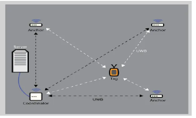
The implementation phase consists of five devices, four of the devices are installed in known location in a room and they are called anchors and the other device is a movable one where it is location is going to be found, this device is called tag. From the four anchors one device is selected as a coordinator, this device is responsible for calculating the distance and controlling the media accesses. In the implementation the tag will send a signal at every 15 sec, when the anchors receives this message they resent to the coordinator, then the coordinator will calculate the distance the tag.
This report is organized as follows
A. Chapter II discusses Theory and Background
B. Chapter III discusses Design and Implementation
C. Chapter IV discusses Results and Discussions
II. THEORYANDBACKGROUND
A. Wireless Personal Area Networks (WPAN)
Wireless Personal area network (WPAN) is a network of devices around the vicinity of individual persons to mention, Bluetooth and infrared communications. The communication range of WPAN could reach up to hundred meters. The IEEE 802.15 working group is responsible for ratifying and maintaining WPAN standard. The task group 4(TG4) of this workgroup is responsible for finding solutions for low power ,high efficiency and low complexity communication that allow devices to work and communicate for a month to years using only batteries. Some applications that need such systems include Sensor networks, remote area control and Smart Bridge. The IEEE 802.15.4a standard specifies the Physical (PHY) layer and MAC layers for low power WPAN standards. This standard gives two alternate PHY these are.
1) Chirp Spread Spectrum (CSS PHY): This is used in devices moving at high speed and longer range communication.
2) Ultra Wide Band PHY (UWB PHY): This is used for devices that require lower power, lower cost and higher precision ranging. This physical Layer standard also gives high resistance to fading and interference
B. Localization Techniques
Localization is technique of finding the accurate position of a moving object i.e. the coordinate axes. To do localization one can use time of arrival, difference in time of arrival or angle of arrival to known location. Since the system implemented is time based, Time of arrival (TOA) and Time Difference of Arrivals are going to be discussed here; interested reader about angle of arrivals (AOA) can read [17].
C. Time of Arrival (TOA)
The main idea behind TOA is shown in Fig 1.The three nodes A, B, and C are located at known locations and they have been synchronized .When the mobile node D broadcast a message by embedding the transmit time in the broadcast message .When each reference nodes A, B and C receives the broadcast messages they can easily calculate the time of flight (TOF) by decrementing the time embedded in the message from the time that they receive the broadcast message. To calculate the distance from the mobile node D they can simply multiple the TOF by multiplying the speed of light. Then they can pass this to central coordinator to calculate the actual position of the mobile device, the central coordinator can calculate the distance based on eq 1 and eq 2.
Figure 1: Time of Arrival Localization
--- (eq1)
Where (xa,ya) the location of node A,
(xb,yb) the location of node B,
(xc,yc) the location of node C
(x,y) the location of mobile node D.
Ra, Rb,Rc, are distances to the mobile node D
The coordinator can calculate by solving the following matrix
--- (eq2)
The systems four reference node to calculate 3D dimensions, and for 2D calculation the system needs there fixed reference nodes.
Technology (IJRASET)
III.TIMEDIFFERENCEOFARRIVAL(TDOA)
Fig 2 shows the technique behind TDOA localization; in TDOA system implemented all reference nodes are located in a known location .In the system the mobile nodes D to all reference nodes then the reference nodes notes down the time they receive, as they locate at different location they will receive the signal at different times and they will send this time they receive to the coordinator then the coordinator take the difference between the message they receive and it receive the message from them and calculate the distance according to eq 3.[4]
Figure 2: Time Difference of Arrival Localization
In order to calculate the following assumption are taken
A. It assumed that the movable device is located at coordinate (x,y,z)
B. Node R, L, and Q are nodes located at the Right, Left, and Quadrant Location (xR,yR,,zR) , (xL,yL,zL) and (xQ,yQ,,zQ)
respectively.
C. Node C is the Coordinator which is responsible for calculating the position of the nodes and also the access of the shared media is controlled by the coordinator and it is also located at (x,y,,z)
Then the arrival times at these nodes can be calculated as (eq 3)
After the signals have been broadcasted to the coordinator the difference in time of arrivals can be calculated as in (eq 4)
Each equation in (4) defines a separate hyperbola, the solution of would be the intersection point as shown in Fig 2.
IV.DESIGNANDIMPLEMENTATION
Figure 3: Localization system
A. Message Exchanged formats
[image:5.612.95.551.342.436.2]Fig 4 shows the ranging frame format of IEEEE802.15.4 standard the payload part of the frame has been changed for localization purpose
Figure 4: Localization Frame format
The IEEE 802.15.4a standard MAC frame formats can be described as follows
1) Frame Control: Describes what kind of frame is it? It can be Beacon, Acknowledgment, Data or Command
2) Sequence Number: The bytes are numbered in sequence; it denotes the sequence of the byte sent.
3) PANID: Sometimes WPAN can have cluster of many nodes together, in this case PANID defines and distinguishes which
cluster the node belongs.
4) Destination Address: It is the address of a destination node that will accept the message.
5) Source Address: It is the address of a source node that sent a message.
6) Payload: It is the part where it carries data, this part of the frame programmed to denote the localization
7) Frame Check Sequence (FCS):This is for the error checking
In the localization there are four POLL MESSAGE, REPLAY MESSAGE, FINAL MESSAGE, and TD Message.
1) POLL MESSAGE: Any device whose joining the network sends this message, each message of this time are associated with time out if the device didn’t receive the reply within this time limit it will send this message again.
2) REPLY MESSAGE: The coordinator reply this message in response to the POLL MESSAGE.
3) FINAL MESSAGE: If POLL-RESPONSE message is successful ,then to calculate two way time of flight the FINAL MESSAGE is sent by the tag/anchor to the coordinator, this message also have a time out associated to it
4) REPORT MESSAGE: Sent by the coordinator to the sender of the FINAL MESSAGE, this message contains six time values for synchronization purpose
5) POLL RECIVED TIME: The time the POLL MESSAGE coordinator receives the frame.
6) REPLY SENT TIME: The time the coordinator sent REPLY MESSAGE
Technology (IJRASET)
8) SYNC_TIME (Synchronizing Time): This time tells the relative drift in time between the sender of the FINAL MESSAGE
and the coordinator.
9) Slot_Number: This time is used for synchronization purpose only, it tells the slot which is allocated for the device that sends the FINAL MESSAGE, at what time it can transmit /receive.
10) TD MESSAGE: After synchronization is achieved, the next phase is to calculate the distance of the movable device then, this message signifies it is only for the purpose of synchronization.
B. Medium Access Design
Since the medium of the system is shared and needs synchorinization, it is decided to select one device is selected to coordinate this process, this devices is called the coordinator. Since the MAC layer should be efficient in battery usage the design that is selected is Scheduled Based MAC.
The first phase of medium access is synchronizing of all devices according to coordinator time base. The step that is followed
1) First synchronizing the anchors involved
2) Then synchronize the movable device (tag) Both of the steps followed the same procedure:
The device that wants to initialize synchronization will send a POLL MESSAGE to the coordinator and replied by the coordinator by REPLY MESSAGE from the coordinator side, the device that sent the POLL MESSAGE send the FINAL MESSAGE if it receive the REPLY MESSAGE before the timeout expires, if not it will restart the process again by sending POLL MESSAGE again, when the coordinator receives the FINAL MESSAGE it will send the REPORT MESSAGE by embedding the six time stamps discussed in 3.1.
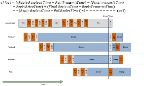
[image:6.612.91.556.354.632.2]The device that receive REPORT MESSAGE will correct its time according to eq(5) and the synchronization process is depicted in fig 5
Figure 5: Synchronization Phase
In the figure 5
RX, TXP, TXR, TXF, TXRP, TXTD are meant to Listen, Transmit POLL, Transmit REPLY, Transmit FINAL ,Transmit Report and Transmit TDOA messages respectively
Sleep means power of all the necessary radios to reduce energy consumption.
assumed also the synchronization process takes 1 sec at any moment any device can go out of synchronization so it has to resynchronize again in order to resynchronise,the resynchronization time is calculated in advance using Moving Average Drift Compensation (MADC).As in [19] the offset time that one will synchronization can easily estimated in eq(6).
Where,
α is a waiting factor =0.1
The resynchronization phase is shown in fig 7
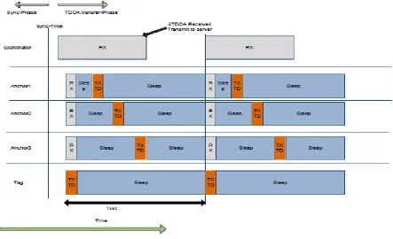
Once the synchronization phase is completed the next phase will be data transfer phase, in the data transfer phase ,the first slot number is given to the movable device (tag), which broadcast TDOA signal which is received by the by the anchors ,then the anchors will sent to the coordinator when its time (slot number ) reaches, after the coordinator receives all the four TDOA messages including the tag TDOA message it will pass it to the position server to which the position is re-calculated.
[image:7.612.82.525.292.562.2]The detail this message is depicted in Fig 6.
Figure 6: Data (TDOA) transfer phase
In fig 7 Anchor 3 losses it synchronization, then it will wait to its slot time and try to resynchronize again.
Technology (IJRASET)
Figure 7: Resynchronizarion Phase
V. MEASUREMENTRESULTANDDISCUSSION
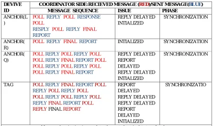
The measurement has been done in the same room; the tag has been operated inside the four nodes as can be seen in fig 3. Since the connection between the position servers has not yet implemented, I have used UART (Universal Asynchronous Receiving and Transmitting) interface to see the packet coming and leaving from the coordinator. The device that sent/receive message can be easily differentiated. Table 1 shows the message and the results obtained in system.
TABLEI
MEASUREMENT AND RESULT
DEVIVE ID
COORDINATOR SIDE:RECIEVED MESSAGE (RED)/SENT MESSAGE(BLUE) MESSAGE SEQUENCE ISSUE PHASE
ANCHOR(L )
POLL REPLY POLL RESPONSE POLL
RESPLY POLL REPLY FINAL REPORT REPLY DELAYED INTIALIZED SYNCHRONIZATION ANCHOR( R)
POLL REPLY FINAL REPORT INTIALIZED SYNCHRONIZATION
ANCHOR( Q)
POLL REPLY POLL REPLY POLL POLLREPLY FINAL REPORT POLL POLL REPLY POLL REPLY POLL POLL REPLY FINAL REPORT
REPLY DELAYED REPORT DELAYED REPLY DELAYED INTIALIZED SYNCHRONIZATION
TAG POLL REPLY FINAL REPORT POLL
REPLY POLL REPLY POLL POLL REPLY POLL REPLY POLL REPLY FINAL REPORT POLL
REPLY FINAL REPORT
REPORT DELAYED REPLY DELAYED REPLY DELAYED REPORT DELAYED INTIALIZED SYNCHRONIZATIO
TAG TD(1) DATA TRANSFER ANCHOR(L
)
TD(2) DATA TRANSFER
ANCHOR( R)
TD(3) DATA TRANSFER
ANCHOR( Q)
TD(3) DATA TRANSFER
Now coordinator has received 4 timestamps, it can send all time stamps to the position server ,the distance of the tag from the coordinator is 2.5m,but the coordinate found as calculated by eq(3) and eq(4) is (2.09,3.11) with a radius of 3.74m.the deviation is 1.24m
TAG TD(1) DATA TRANSFER
ANCHOR(L )
TD(2) DATA TRANSFER
ANCHOR( Q)
POLL REPLY POLL REPLY POLL
REPLY POLL REPLY
POLL REPLY FINAL REPORT
ANCHOR LOSES SYNCRONIZATIO N RE-SYNCHRONIZED RE-SYNCHRONIZATION
Since new synchronization is in effect the coordinator will simply discard the previous TDOA messages and wait for new ones
TAG TD(1) DATA TRANSFER
ANCHOR(L )
TD(2) DATA TRANSFER
ANCHOR( R)
TD(3) DATA TRANSFER
ANCHOR( Q)
TD(3) DATA TRANSFER
Now coordinator has received 4 timestamps, it can send all time stamps to the position server ,the distance of the tag from the coordinator is 2.9.m,but the coordinate found as calculated by eq(3) and eq(4) is (2.11,3.23) with a radius of 3.86 4m.the deviation is 0.94m
The overall measurement shows an average result is 1.09m deviation in radius compare to the actual measurement, this can be improved y accurate synchronization.
VI.CONCLUSION
In this paper an IEEE 802.15.4a standard MAC layer has been designed, implemented and the measurement result also discussed. The initial assumption was to get an accuracy of ± 30cm deviation in radius, but to achieve this the system needs 0.1ns synchronization offset which is a very difficult task to achieve and no one has able to implemented localization system of this accuracy so far in UWB technology, so the system that is builded and tested come with an average of ±1.1m which can be improved if proper synchronization is achieved.
The second goal of the project was a battery life that reaches from 2-4 years; this is not implemented because the physical layer transceiver IC that is used still doesn’t support sleep, so this phase is replaced by an ideal phase that has power consumptions of 8mW, that force the nodes to only wait for 10-15minuts.
REFERENCES
[1] [9]. Y. Al-Obaisat and R. Braun,” Wireless Sensor Networks: Architectures. Protocols, Applications, and Management,” Auswireless Conference, 2006
[2] IEEE 802.15.4a WPAN Low Rate Alternate PHY Task Group 4a (TG4a), [online]: Available: http://www.ieee802.org/15/pub/TG4a.html. Last Accessed:
Aug 2, 2014
[3] Xin-long Luo, Wei Li, and Jia-ru Lin, “Geometric Location Based on TDOA for Wireless Sensor Networks,” ISRN Applied Mathematics, vol. 2012, Article ID 710979, 10 pages, 2012. doi:10.5402/2012/710979
[4] H. Karl, A. Willig, “Protocols and Architectures for Wireless Sensor Networks,” John Wiley &Sons, New York, 2005
[5] P. Lin, C. Qiao, and X. Wang, “Medium Access Control with a Dynamic Duty Cycle for Sensor Networks,” IEEE WCNC, vol. 3, Mar. 2004, pp. 1534–
39.
Technology (IJRASET)
[7] Wireless LAN Medium Access Control (MAC) and Physical Layer (PHY) Specification, IEEE Std. 802.11, 1997
[8] Benoit Denis, “ UWB Localization Techniques, “In support of TG4a Ranging Subcommittee work, IEEE P802.15 working group for WPAN,
doc:IEEE802.15-04/418vo,August ,2004.
[9] R. Roberts, “TDOA Localization Techniques,” In support of TG4a Ranging Subcommittee work, IEEE P802.15 working group for WPAN, IEEE
802-15-04-0572-004a, October, 2004.
[10] Z. Jinyun Zhang, P.V. Orlik, Z. Sahinoglu, A.F. Molisch, P. Kinney, "UWB Systems for Wireless Sensor Networks," Proceedings of the IEEE , vol.97, no.2, pp.313-331, Feb. 2009
[11] Ilker Demirkol, Cem Ersoy, and Fatih Alagöz, “MAC Protocols for Wireless Sensor Networks: a Survey,” IEEE Communications Magazine, pp.115-121,
April 2006
[12] Joseph Kabara and Maria Calle, “MAC Protocols Used by Wireless Sensor Networks and a General Method of Performance Evaluation,” International
Journal of Distributed Sensor Networks, vol. 2012, Article ID 834784, 11 pages, 2012. doi:10.1155/2012/834784.
[13] Rilind Ballazhi, “Wireless Indoor Positioning Techniques,” Communication Systems V. IFI Technical Report, IFI 2012.06, pages 55-67, August 2012
(2002) The IEEE website. [Online]. Available: http://www.ieee.org/
[14] M. Shell. (2002) IEEEtran homepage on CTAN. [Online]. Available: http://www.ctan.org/tex-archive/macros/latex/contrib/supported/IEEEtran/
[15] FLEXChip Signal Processor (MC68175/D), Motorola, 1996.
[16] Tingcong Ye, Michael Walsh, Peter Haigh, John Barton, Alan Mathewson, Brendan O’Flynn, “Experimental Impulse Radio IEEE 802.15.4a UWB
Based Wireless Sensor Localization Technology: Characterization, Reliability and Ranging,” technical report, Tyndall national institute, June, 2011.
[17] Zafer Sahinoglu, Sinan Gezici, “Ranging in the IEEE 802.15.4a Standard TR2006-0 97”, December 2006.
[18] .G. Lu, B. Krishnamachari, and C. S. Raghavendra, “An Adaptive Energy-Efficient and Low-Latency MAC for Data Gathering in Wireless Sensor Networks,” Proc. 18th Int’l. Parallel and Distrib. Processing Symp., Apr. 2004, p. 224.[12].
[19] Rainer Mautz,” Indoor Positioning Techniques,” habilitation thesis, ETH-Zurich, Feb 2012
[20] M. Brzozowski, H. Salomon, and P. Langendoerfer, “On efficient clock drift prediction means and their applicability to IEEE 802.15.4,” in Proceedings