International Journal of Emerging Technology and Advanced Engineering
Website: www.ijetae.com (ISSN 2250-2459, ISO 9001:2008 Certified Journal, Volume 7, Issue 9, September 2017)
329
Finite Element Analysis of Dynamic Pressure on a Floating
Platform Due to Surface Waves
Bhagirathi Tripathy
1, Pratap Kumar Pani
21Asst. Professor, 2Professor, Department of Civil Engineering, IGIT, Sarang, Dhenkanal, Odisha, India-759146.
Abstract—The hydroelastic response of mat-type floating structures (VLFS) due to severe sea waves must be assessed for safety and survivability. An efficient and robust nonlinear hydroelastic model is required to predict accurately the motion and the dynamic loads on a VLFS due to such waves. Here, an efficient finite element technique is developed to determine the dynamic pressure on a floating plate subjected to surface waves. The coupled fluid structure system is solved in a decoupled way by transmitting the pressure to the platform and acceleration of the platform to the fluid till both equilibrium and compatibility is achieved. The unknown time dependent boundary conditions on the free surface and the interface are evaluated by a time-stepping procedure, which gives a time domain solution. The bending characteristics of the platform are studied.
Keywords— Velocity Potential, FEM, VLFS, hydroelasticity, Dynamic Pressure, Wave structure Interaction.
I. INTRODUCTION
In the analysis of floating structures, the dynamic response of structures to waves is the most important factor. A small-scale floating structure can be analyzed as a rigid body. However, for a large-scale floating structure like floating vessel, floating bridge or floating airport, the elastic deformation cannot be ignored, and then the effect of flexibility should be considered in the wave-structure interaction. The rigid body motion on the other hand, will be small and may be disregarded, because the wave length of sea waves of practical concern is obviously too short compared with the huge size of the structure to induce rigid body motions.
Here a very large floating structure (VLFS) of thin and rectangular plate configuration floating on water of shallow depth is considered .The linear shallow water theory in addition to a small draft approximation is made. The shallow water assumption is made because floating structures are intended to be installed in coastal areas. It is assumed that the waves are incident head on to the long plates.
The width of an actual airport, however, will be very large compared with the wave length of incident waves. In this paper, we study the case in which both the width and the length of the structure are very large, yet the former is much smaller than the latter. In the earlier studies, the investigators have calculated the wave-induced deformation of floating structure by the radiation-diffraction theory, in which the velocity potentials are expressed as a linear summation of incident, radiation and diffraction waves. This theory is available for the analysis of periodic waves, however it is difficult to solve the problem with non-periodic waves, such as the random waves in actual seas. Approaches used for analysis of wave-ship or wave–structure interaction [Faltinsen1990] will be applicable but may not always be the best for straightforward prediction of the elastic response of large floating structures. The water motion is represented by its velocity potential and is solved using the linear potential theory. The platform is in most of the cases, is represented with classical thin plate theory or Kirchhoff(1850) plate theory to describe its motion. There are a number of ways to solve the coupled water and floating platform. Kashiwagi (1998) used a combination of the pressure distribution and mode expansion methods, where the numerical solution was given by way of B-spline functions and the Galerkin method. Hermans (2000) and Meylan (2002) used boundary element method (BEM) to represent the velocity potential and the finite element method (FEM) for the thin plate of arbitrary geometry.
International Journal of Emerging Technology and Advanced Engineering
Website: www.ijetae.com (ISSN 2250-2459, ISO 9001:2008 Certified Journal, Volume 7, Issue 9, September 2017)
330
Second, the numerical calculation of the moments and shear forces in the Kirchhoff plate is not accurate, since the stress resultants depend on the second and the third derivatives of the displacement w, where w is usually some approximation function. This inadequacy is particularly serious when FEM is employed, because of the polynomial functions used to approximate the displacement. Therefore, in order to obtain a more accurate calculation of the plate deformation, the first-order shear deformation plate theory (also known as Mindlin plate theory) is used.
In the present study, a finite element approach is developed to simulate the interaction of floating platform with the waves. In order to examine the validity and applicability of the proposed numerical method the calculated results are compared with previous available data.
II. APPLICATION OF RECTANGULAR PLATE AS VLFS.
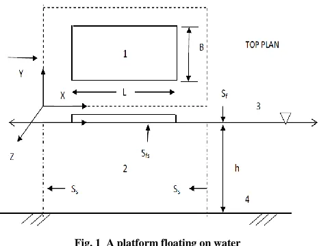
[image:2.612.53.286.380.560.2]Let us consider a platform of Length l and width b floating on a water of depth h under the action of a incident wave (Fig-1)
Fig. 1 A platform floating on water
The conservation of mass and momentum leads to the Laplace equation given as
2
, ,
0
p x y z
(1)where,
2is the Laplacian operator2.1 Boundary Conditions.
Boundary Conditions (Linearised approximation of the free surface)
Assuming a linearised approximation of the free surface,
1
p
p
p
n
z
g
(2)(a) Top surface (Sf) excluding the platform area:
The actual free surface is nonlinear in nature. However, a linear approximation of the free surface may be made when the amplitude of the surface wave is relatively small in comparison to the depth. The free surface boundary condition may be written as
1
p
p
p
n
z
g
(3)(b) Fluid-structure interface (Sfs):
The top surface of the fluid domain over which the platform is floating, the boundary condition may be expressed as
f
p
a
n
(4)Where,
p x y z
( , , )
is the pressure anda x y
( , )
is the acceleration of the fluid-structure interface at that instant of time in the direction of the outward normaln
to the interface.(c) Four side surfaces (Ss):
( , 0, )
0
p
x
z
n
(5)
( , , )
0
p
l y z
n
(6)
( , , )
0
p
x b z
n
(7)
(0, , )
0
p
y z
n
(8)(d) Bottom surface (Sb):
( , ,
)
0
p
x y
h
n
(9)2.2 Finite Element Formulation
International Journal of Emerging Technology and Advanced Engineering
Website: www.ijetae.com (ISSN 2250-2459, ISO 9001:2008 Certified Journal, Volume 7, Issue 9, September 2017)
331
20
e
T
e
N
p d
(10)Here,
and
e refer to the summation of all the elements and one element respectively. The weak form of eqn.2 may be written as
.
0
e e
T T
e e
p
N
p d
N
d
n
(11)e
indicates the total boundary surface of the element. In concise matrix form, this may be represented as
G
p
B
(12) in which,
.
e
T
e
G
N
N d
(13)
eT
e s
p
B
N
d
n
(14)s
refers to the total boundary surface of the fluiddomain.
N
is the shape function for the total domain given as
1,
2,
3 n
N
N N N
N
(15) The boundary term
B
may be split into its components as
B
B
f
B
fs
B
b
B
s (16)At the free surface
B
f1
p
p
p
n
z
g
(17)
f e
T
f e
S
p
B
N N d
g
(18)At the fluid structure interface
B
fs ,sincef
p
a
n
B
fs
f
R
fs
a
(19)where,
fs e
T
fs s e
S
R
N N d
(20)s
N
is the shape function of the plate corresponding tonodes of the fluid-structure interface and
a
is the vector of nodal accelerations.At the bottom surface of the fluid domain
B
b , as the normal pressure gradient vanishes
B
b
0
(21)At the four side faces of the fluid domain
B
s ,since0
p
n
Hence
B
s
0
(22) Combining all these, eqn. 12 may be represented as
E
p
G
p
f
R
fs
a
(23)The terms of eqn. 23 are defined as
1
T
e
S f e
E
N N d
g
(24)The dynamic equilibrium equation for the platform without considering the effect of damping is given as
M W
K W
F
(25)where,
M
&
K
are the mass and stiffnessmatrices of the platform and
W
&
F
are theInternational Journal of Emerging Technology and Advanced Engineering
Website: www.ijetae.com (ISSN 2250-2459, ISO 9001:2008 Certified Journal, Volume 7, Issue 9, September 2017)
332
III. NUMERICAL RESULTS AND DISCUSSION
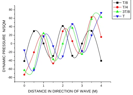
[image:4.612.335.549.156.321.2]The authenticity of the technique is compared with available literature. To make the comparison logical, a floating platform of same size and same wave characteristics have been studied first. A rectangular platform of 3 m x 10 m and thickness of 20 mm having mass density of 942 Kg/m3 is considered first to compare the results and it is found that the results (Fig.2) match rationally except at the beginning. The time period of the wave was considered to be 1.2 second and time interval of calculation was considered to be 1/100th of it. The difference in amplitudes of deformation in the beginning may be due to difference in approach. The present investigation has been made using finite element method for both the fluid and the structure whereas Liu and Sakai (1996) used BE method for fluid and finite element method for the structure. The effect of flexibility of the platform on its deformation was investigated by comparing the amplitudes of displacement of the platform with respect to the deformation at the starting edge. It is observed ( Fig. 3) that flexibility enhances the deformation of the platform. However, towards the tail end the deformation is less and this may be due to the fact that a flexible platform is a better dissipater of energy. The wave length below the platform increases towards its tail end and the dynamic pressure decreases. However for when the frequency increases and approaches to the natural frequency (Fig. 4) of the platform the dynamic pressure goes on increasing.
[image:4.612.333.561.371.534.2]Fig. 2 Ratio of amplitude of the platform with amplitude of wave at time t = T/4
Fig. 3 Deformation of the platform with respect to that of the incoming wave at time t = T/8
0 1 2 3 4
-80 -60 -40 -20 0 20 40 60 80
D
Y
N
AM
IC
PR
ESSUR
E
N
/SQ
M
DISTANCE IN DIRECTION OF WAVE (M)
[image:4.612.60.274.485.649.2]T/8 T/4 3T/8 T
Fig.4 Dynamic pressure on the platform at various time intervals
IV. CONCLUSION
The dynamic pressure on a floating platform is studied using a simple approach considering fluid structure interaction of the wave with the platform. The horizontal size of this platform is huge compared with the wavelength, while the draft is much smaller than the wave length. The fluid–plate interaction is solved mathematically by considering that the plate bottom Surface is located at the water surface. In the present approach the main concern is to solve for the dynamic Pressure and the resulting stresses for design purposes.
0 2 4 6 8 10
0.05 0.10 0.15 0.20 0.25 0.30 0.35 0.40 0.45 0.50
Am
p
li
tu
d
e
r
a
ti
o
(
)
Distance (m)
present Liu & Sakai
0 2 4 6 8 10
-0.2 0.0 0.2 0.4 0.6 0.8 1.0 1.2 1.4
R
a
ti
o
a
m
p
litu
d
e
s
(
)
Distance (m)
International Journal of Emerging Technology and Advanced Engineering
Website: www.ijetae.com (ISSN 2250-2459, ISO 9001:2008 Certified Journal, Volume 7, Issue 9, September 2017)
333
The solution is made by matching the deformation and Dynamic pressure of the platform with the fluid below it and the platform edges satisfying the conditions of zero bending moment and zero shear force.
REFERENCES
[1] Faltinsen, O.M., 1990. Sea Lords on Ships and Offshore Structures.
Cambridge University Press, Cambridge.
[2] Kirchhoff, G., U¨ ber das Gleichgewicht und die Bewegung einer
Elastischen Scheibe. 1850. Journal fu¨ r de Reine und Angewandte Mathematik, 40, pp 51–58.
[3] Kashiwagi, M., 1998. A B-spline Galerkin scheme for calculating
hydroelastic response of a very large floating structure in waves. Journal of Marine Science and Technology 3, 37–49.
[4] Hermans, A.J., 2000. A boundary element method for the interaction
of free-surface waves with a very large floating flexible platform. Journal of Fluids and Structures 14, 943–956.
[5] Meylan, M.H., 2002. The wave response of ice floes of arbitrary
geometry. Journal of Geophysical Research—Oceans 107 (C1), 1– 15.
[6] Mindlin, R.D., 1951. Influence of rotary inertia and shear on flexural
motions of isotropic elastic plates. Journal of Applied Mechanics 18, 31–38.
[7] Liu, X. and Sakai, S. (1996.) Analysis on the Interaction of Waves