© 2015, IRJET ISO 9001:2008 Certified Journal Page 2588
IMPLEMENTATION OF BOTTLE FILLING AND CAPPING USING PLC WITH
SCADA
Anup Dakre
1, Junaid G. Sayed
2, Ekata A. Thorat
3, Aousaf Ahamad Md. Aves Chaudhary
41
Assistant professor , Department of Electrical Engineering , K.J. College of Engineering and Management
Research , Pune , Maharashtra , India.
2
Student – Bachelor of Engineering , Department of Electrical Engineering , K.J. College of Engineering and
Management Research , Pune , Maharashtra , India.
3
Student – Bachelor of Engineering , Department of Electrical Engineering , K.J. College of Engineering and
Management Research , Pune , Maharashtra , India.
4
Student – Bachelor of Engineering , Department of Electrical Engineering , K.J. College of Engineering and
Management Research , Pune , Maharashtra , India.
---***---
Abstract – The objective of this paper is to design, develop and monitor “Bottle filling and capping with PLC”. This work provides with a lot of benefits like low power consumption, low operational cost, less maintenance, accuracy and many more. This project is based on Industrial Automation and is a vast application used in many industries like milk industries, chemical, food, mineral water and many industrial manufactures. A prototype has been developed to illustrate the project.
Filling is the task that is carried out by a machine and this process is widely used in many industries. In this project, the filling of the bottle is controlled by using a controller known as PLC which is also the heart of the entire system. For the conveyor system, a DC motor has been selected for better performance and ease of operation. Various sensors has been used to detect the position of the bottle. In our project we have use less numbers of system hence the overall cost has been reduced to an extent. Ladder logic has been used for the programming of the PLC, which is the most widely used and accepted language for the programming of the PLC. The PLC used in this system is an Allen Bradley Pico-controller which makes the system more flexible and easy to operate.
Key words : Allen Bradley , PLC , Proximity sensor , Conveyor belt , SCADA , Ladder Logic etc.
1.
INTRODUCTION
The word “Automation” itself emphasizes on making a typical process automatic which in turn will reduce the human work and thus will promote productivity. Industries will be productive only when they will adopt to the high-end technology available in the markets. So by implementing the use of PLC’s in their processes, industries will take a step forward towards the era of new industrialization.
PLC plays a very important role in the world of automation. It is the main part of the system which makes the whole process simple, flexible and accurate. A bottle filling system with PLC allows the user to fill the bottle till a desired level without wastage of the liquid. Ladder logic is used to control the sequence of the PLC. The system is controlled by a Allen Bradley PLC which operates on 24V DC and is a compact PLC which has a fixed number of inputs and outputs. In addition to this, the use of SCADA has also been implemented for the monitoring of the entire system.
2.
OBJECTIVE
© 2015, IRJET ISO 9001:2008 Certified Journal Page 2589
3.
ALGORITHM
STEP I : Press the “START” Push Button.
STEP II : Then the “MOTOR” starts and the container moves forward.
STEP III : If the container is made up of any metal (eg: tin, silver etc.) the bottle will be pushed by the piston.
STEP IV : If the container is made of non-metal (eg: plastic) then is will move forward ad will stop below the solenoid valve.
STEP V : After some delay the valve will turn “ON” and the bottle will get filled.
STEP VI : After the bottle is filled, a delay is provided and then after the delay the motor
STEP VII : As the bottle is moving forward, the cap will be placed by the cap hopper automatically.
STEP VIII : After the cap is placed the bottle will move further and the bottle will stop below the capping piston.
STEP IX : After some delay the capping piston will come down and the cap will be placed tightly.
STEP X : After the cap is placed he bottle will go further for different processes in industry.
4.
PROCESS DIAGRAM
Fig. 1 Working process diagram
5.
OUR PROPOSED SYSTEM
Our project is based on industrial automation and PLC is the heart of automation. The hardware and software are the two important areas in our project.
5.1 Hardware Description
In this project we have used a Allen Bradley Pico-controller for controlling the inputs and outputs. The model number of our PLC is 1760 18BWB-EX. Input supply to the PLC is given through a SMPS. The rating of the SMPS is 24V DC 5Amp. The PLC we used is a compact PLC which has fixed number of inputs and outputs. In our PLC, we have 12 digital inputs and 6 digital outputs. Various proximity sensors has been used for the positioning of the bottle. A DC motor is used for the conveyor system. The ratings of the DC motor is 12V with 8 RPM for high torque. Toggle switch and push buttons are used which acts as the input to the PLC.
5.2 Software Description
There are five important languages which are used for the programming of the PLC. The list of the methods are as follows :
Functional Block Diagram (FBD)
Structure Text
Instruction list
Flow chart
Ladder diagram
Out of these five languages, ladder diagram is the most widely used language and is simple as compared to other languages.
6.
SELECTION CRITERIA FOR PLC
While selecting a PLC, various factors should be considered as per the application. The important factors that affect this criteria are :
Number of Inputs and Outputs.
Scan Time
Communication Protocol
Memory Size
Software
© 2015, IRJET ISO 9001:2008 Certified Journal Page 2590
[image:3.595.43.278.373.690.2]Fig. 2 Line Diagram of Allen Bradley PLC
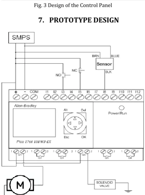
Fig. 3 Design of the Control Panel
[image:3.595.366.500.377.474.2]7.
PROTOTYPE DESIGN
Fig. 4 PLC based Water bottle Filling and Capping
The above image shows the interfacing of the various inputs and outputs connected in our project. The PLC is given a constant 24V DC supply from the SMPS. Two push buttons are used. One for the turning “On” of the system and the other if in case of emergency to stop the System. Also proximity sensors are used got the detection of bottle. A DC motor of 12V rating is connected to the conveyor and a solenoid valve is used for flow of water which fills the liquid in the bottle.
As shown in figure 4 an LCD is provided for the designing and viewing purpose. This device can be used as a hand-help device for the programming. The power/run indicators shows the condition of the PLC. If the LED is constantly ON that means the PLC is in the OFF state and we can edit the program in this condition. If the LED is blinking then the PLC is in the RUN mode and we cannot access the program in this condition. Navigation button are provided for the user to explore the functions in the PLC.
Fig. 5 Conveyor System
[image:3.595.350.505.380.705.2]© 2015, IRJET ISO 9001:2008 Certified Journal Page 2591
8.
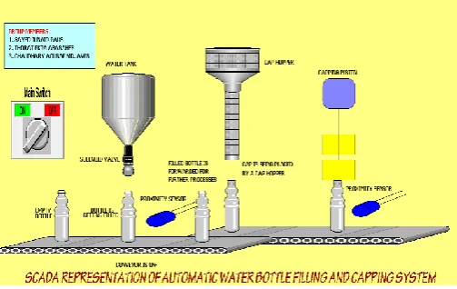
SCADA
[image:4.595.316.553.123.162.2]SCADA stands for “Supervisory Control And Data Acquisition. Previously without SCADA an industrial process was entirely controlled by PLC, CNC, PID & micro controllers having programmed in certain languages or codes. These codes were either written in assembly language or relay logic without any true animation that would explain the process running. With the development of SCADA we can now view the graphical animation of the entire process and also can control limited but important function through the software. Now a days all the control systems are coupled with HMI or SCADA as it gives an animated view by sitting at one place while the process is at another place.
Fig. 7 SCADA view of the entire process
Various vendors of SCADA are :-
Wonderware – Intouch
Siemens – WinCC
GeFanuc – Cimplicity
Movicon – Progea
Delta – Winlog
In our project we have used Wonderware since it is easy to interface the PLC with the Intouch software
[image:4.595.37.289.308.467.2]9.
INTERFACING OF SCADA WITH PLC
Fig. 8 SCADA Interfacing
The software of the SCADA is firstly installed on the server. Various protocols are used for the interfacing of the PLC and the server. Mostly used protocols are serial protocol i.e RS-232 for serial communication. The inputs and outputs are directly connected to the PLC and they work on the ladder logic provided by the user. The main advantage of SCADA is that we can execute limited control options from the software without being present near the system.
10.
LIMITATIONS
The only limitation of this system is that it can fill only few bottles in a minute. As required by the industry this system is not so fast and hence lacks productivity. Also this system is not so robust as demanded by the industries. Also this system only fills liquid for a particular bottle of same height and width.
11.
FUTURE WORK
With the help of proper and efficient components, the drawback of productivity can be overcomed. Here we have used a two port valve for the filling purpose. Instead of that we can use a jet nozzle for the filling purpose since it will reduce the time of filling operation. That means more bottle will be filled and this will reduce the time and increase productivity. Also level sensor can be used for the level detection in the bottle while filling. Alarm function can be added in case of any mis-operation. We can redesign the whole system again for a new bottle or any other specification.
12.
CONCLUSION
© 2015, IRJET ISO 9001:2008 Certified Journal Page 2592 Implementation of automation increases
productivity which in turn increases the economy. Installing PLC in the system makes it handy to control the entire system. Although the initial investment is high as the PLC and its components are far costlier as compared to other methods. The language used for the programming of the PLC is ladder logic. This language is very useful since most of the industrial application use this language. One of the other feature in this system is the implementation of SCADA. This technology is growing fast and will be very famous in the coming years. Mainly SCADA is used for the monitoring purpose but we can also control functions like stating or stopping the conveyor from the system.
13.
REFERENCES
[1]. Hemant Ahuja, Arikha Singh, Saubhagya Tandon, Shreya shrivastav, Sandeep Patil, ‘‘ Automatic Filling Management System For Industries’’ IJETAE, Vol. 4, Special Issue 1, February – 2014
[2]. Nabil Shaukat, “A PLC Based Automatic Liquid Filling Process”, IEEE, publication page No. 226-233, 2002.
[3]. Ahmed ulla Abu Saeed, Md. Al-mamun, A.H.M. Zadidul Karim, ‘‘ Industrial Application Of PLCs in Bangladesh’’ IJSER, Vol. 3, Issue 6, June 2012
[4]. Gray Dunning, “Introduction to programmable Logic Controllers,” Delmar ThomsonLearning1998.
[5]. ZHANG Tianxia, DONG Feng , YUAN Hao
“Application of PLC for Arranging Bottle in Beer Filling Production Line”, Tianjin Key Laboratory of Process Measurement and Control, School of Electrical Engineering and Automation Tianjin University, Tianjin 300072, China.
[6]. T. Kalaiselvi, R. Praveena, Aakansha .R, Dhanya, ‘‘PLC Based Automatic Water Bottle Filling Capping System With User Defined Volume Selection’’ IJETAE, vol. 2, Issue 8, August 2012