International Journal of Emerging Technology and Advanced Engineering
Website: www.ijetae.com (ISSN 2250-2459, ISO 9001:2008 Certified Journal, Volume 6, Issue 1, January 2016)
94
Microcontroller Based Bi-directional DC Motor Control
Prasanna Waichal
School of Electrical and Electronics Engineering, Fiji National University, Suva, Fiji Islands
Abstract— An experimental system for the speed and direction control of brushed DC motor using a microcontroller has been developed successfully. The speed control of the DC motor is achieved using standard PWM techniques in a sensor-less closed loop feedback control fashion. Motor functions such as start-stop, forward and reverse direction and speed increment and decrement are controlled through keyboard commands. The control software for the microcontroller is written in Assembly language. The present paper discusses the experimental system and the test results.
Keywords— Brushed DC Motor, Embedded Systems, Microcontroller, Motor Speed Control, MOSFET, PWM
I. INTRODUCTION
Small brushed DC motors also known as permanent magnet DC (PMDC) motors find their applications in intelligent toys, power tools, robotics, and modern appliances such as printers, scanners, photocopiers, car windows and wiper controls and other industrial applications [1, 2]. The speed control of these motors is achieved by changing the armature voltage applied to the motors [3, 4]. With the availability of microcontrollers, it is easier to achieve the motor speed control using Pulse-Width-Modulation techniques where the pulse width of a square wave decides the average voltage applied to the armature windings and hence the speed of the motor [1]. Moreover, other features such as close loop monitoring and control and fault detection can easily be implemented using microcontrollers. The present paper discusses the experimental implementation of such microcontroller based closed-loop motor speed and direction control system.
II. BASICS OF DCMOTOR CONTROL
To achieve the speed control of a motor, modern technology uses solid-state devices such as Silicon Controlled Rectifiers (SCRs), Power Bipolar Junction Transistors (BJTs), Metal Oxide Field Effect Transistors (MOSFETs) or Insulated Gate Bipolar Transistors (IGBTs). These devices can be controlled with digital control signals from microcomputer or microcontroller devices [3].
[image:1.612.368.519.211.350.2]In order to achieve this, the motors are operated with their Speed-Torque characteristics in one of the quadrant modes as shown in the figure 1. The x-axis describes the speed while the y-axis describes the motor torque.
Figure 1: Motor Operation
As is seen in figure 1, in Quadrant-1 (Q1) the speed and the torque are positive and the device acts as motor converting electrical energy into mechanical energy. The same situation is applicable to quardrant-3 (Q3) the only difference is that both the torque and the speed are reversed but the device still functions as a motor. On the other hand, in quadrant-2 (Q2) and quadrant-4 (Q4) the device acts as a generator or braking system where the mechanical energy is converted into electrical energy. This energy can be absorbed by the drive system or used in braking control [5].
Figure 2 (a-c) discusses various switching topologies for DC motor control to achieve either the motor operation alone or both motor and braking operation in respective quadrants.
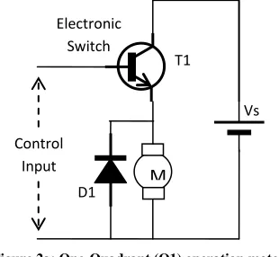
Figure 2a: One-Quadrant (Q1) operation motor drive
In one quadrant operation, only the motor speed control is possible as shown in figure 2a.
Speed (rpm)
To
rq
u
e
τ
+x
-x
+y
-y
Q1 - Motor
Q3 - Motor
Q2 – Brake /
Generator
Q4 – Brake /
Generator
Control Input
Vs Electronic
Switch
T1
[image:1.612.357.512.529.672.2]International Journal of Emerging Technology and Advanced Engineering
Website: www.ijetae.com (ISSN 2250-2459, ISO 9001:2008 Certified Journal, Volume 6, Issue 1, January 2016)
[image:2.612.93.271.212.352.2]95 The switching device such as a MOSFET or a power transistor provides switching of the battery supply Vs to the motor where the speed depends on the average DC voltage applied to its armature windings. Diode D1 acts as a free-wheeling diode for the Back EMF generated by the motor. Direction reversal is however not possible in this mode.
Figure 2b: Two-quadrant operation (Q1, Q2) motor drive with braking control – the Half-Bridge Drive
[image:2.612.62.277.457.599.2]To implement the two quadrant mode with braking control, a Half-Bridge drive method needs to be adopted as shown in figure 2b. Switching device T1 and diode D2 provide the motor speed control drive while T2 and diode D1 are used during braking control. The diodes act a free-wheeling diodes against the Back-EMF as stated earlier.
Figure 2c: Four-Quadrant operation using a full-bridge (H-Bridge) Drive Method
The four-quadrant method employs four switching devices supported with respective free-wheeling diodes connected across each of them. The transistor-diode pair T1-D1 and T4-D4 is turned ON through the control pulses and the motor runs in one direction and the motor current flows say from point A to B as shown by the solid arrow in figure 2c. Devices T2 and T3 are in OFF state during this time.
To change the direction, the speed control pulses are applied to T2-D2 and T3-D3 path making the current through the motor to change its direction from B to A as shown by the dashed arrow in the figure. During this time T1 and T4 are OFF state.
In the present system as it is intended to use the device as motor to convert electrical energy into mechanical energy and therefore, it is apparent from above discussion that in order to implement both speed and direction control the motor should be operated in Q1 and Q3 and the drive required is H-Bridge or full-bridge fashion.
III. BLOCK DIAGRAM OF THE PRESENT SYSTEM
The block diagram of the complete experimental system is shown in figure 3.
A) The choice of Microcontroller device
[image:2.612.337.523.517.699.2]To implement the PWM based control, two candidates were considered. These are PIC16F877 and PIC16F887; both are 8-bit controllers from Microchip Technology Inc. USA. These chips contain an on-chip Analog to Digital Converter (ADC) module with 10-bit resolution. The F877 device has 8 channels of analog inputs while the F887 device has 14 channels. Significant difference and advantage however is with the F887 device with its PWM module. The F877 device only offers a single PWM output channel and thus is only helpful in implementing quandrant-1 operation in implementing speed control only in one fixed direction. On the other hand the F887 device has an ―Enhanced PWM‖ port capable of providing 1, 2, or 4 channel PWM output. This makes it possible to use a Full-Bridge (H-Bridge) motor drive with direction reversal [6, 7].
Figure 3: The System Block Diagram
Control Inputs
Vs
M
D1
D2
Speed T1
T2
Brake
T1 D1
D3
D2
D4 T3
Vs T2
T4
M
A B
Micro-controller
H-Bridge Motor
Drive
12V Battery Current
Sense
Amplifier
PWM
Power Supply Keyboard
Console
M
+5V
International Journal of Emerging Technology and Advanced Engineering
Website: www.ijetae.com (ISSN 2250-2459, ISO 9001:2008 Certified Journal, Volume 6, Issue 1, January 2016)
96 B) The H-Bridge Motor Drive
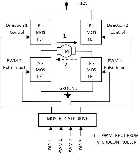
With reference to figure 2c, the top side switching devices were implemented by p-channel power MOSFET of type IRF7425 [8] from International Rectifier (now Infineon). The PWM channel automatically provides the logic level control signals to the respective transistors. The PWM pulses were applied to T3 and T4 depending upon the motor direction. Here n-channel power MOSFETs of type IRF7457 [9] are used. The diode protection is provided by Schottky diodes of type 30BQ015 [10] from Vishay. The microcontroller device provides TTL level (+5V) control signals. In order to drive the MOSFETs a gate drive chip of type TC4428 from Microchip was used as in [1, 11]. Figure 4 illustrates the PWM signals and the Drive switching arrangement.
C) The Sensor-less Feedback Scheme
[image:3.612.327.555.140.392.2]The small motors that are used in the present system are not equipped with any rotary encoder for speed feedback. Therefore a current sense resistor is used in the motor drive. With the motor speed the current through the motor changes. This current flows through the MOSFETs and a sense resistor of value 0.1 Ohms is used from the Source of the MOSFETs to Supply Ground as stated in [1]. Therefore the voltage drop across this resistor is used in a feedback loop for control and fault monitoring applications. Since this value is small, a DC amplifier is used to amplify the voltage to a range of 0-5VDC suitable for the analog input of the on-chip ADC. This will help to implement more sophisticated fault and control algorithms in future developments.
Figure 4: H-Bridge Drive Block Diagram with control signals
D) The Keyboard Control
In the present system, the microcontroller is interfaced with a keyboard to receive input commands from human
users. Functions such as ―RUN/STOP‖,
FORWARD/REVERSE‖ and ―SPEED UP‖ and ―SPEED DOWN‖ are implemented through this keyboard. As stated in the earlier discussion, the motor speed can be controlled by changing the pulse width of the PWM signal. With reference to Table-I, the microcontroller modifies the pulse width by changing the count value in the respective PWM register or sets or resets the direction control bit to achieve the motor direction reversals based on the keys pressed on the keyboard.
Direction 1 Control
PWM 2 Pulse Input
Direction 2 Control
PWM 1 Pulse Input
MOSFET GATE DRIVE
TTL PWM INPUT FROM MICROCONTROLLER
D
IR
1
P
W
M
1
P
W
M
2
D
IR
2
P -MOS
FET
+12V
GROUND N
-MOS FET
P -MOS
FET
N -MOS
FET
1
2
International Journal of Emerging Technology and Advanced Engineering
Website: www.ijetae.com (ISSN 2250-2459, ISO 9001:2008 Certified Journal, Volume 6, Issue 1, January 2016)
97
IV. CONTROL STRATEGY
A) The PWM Module Setup
In order to setup the PWM module, three major parameters need to be programmed – the PWM Frequency as decided by the Period Register, the PWM Width or Duty cycle and the PWM Mode as 1,2 or 4 channel with direction control. The PWM Module uses Timer 2 for its timing generation which in turn is driven by the main controller clock Tosc. The microcontroller is operated at 10MHz Crystal frequency therefore
Fosc = 10MHz (1)
The Time period Tosc is then given as – Tosc = 1/Fosc = 1/ 10MHz (2a)
Tosc = 1/(10* 106 Hz) = 0.1µs = 100ns (2b)
A) The choice of PWM Frequency
The PWM frequency can be set around 1kHz to 20kHz range [1]. However, at lower frequencies an audible tone is heard and can cause annoyance to humans. Towards the higher end, the Rise-Time and Fall-Time of the switching MOSFETs become the governing factor. Therefore an optimum value of 5kHz is chosen for the PWM operation.
To setup the PWM operation, the Period register needs to be loaded with certain hexadecimal count as stated by equation 3.
PWM Frequency = 1 / PWM Period (3a)
PWM Period = (Period Register 2 + 1) * 4 * Tosc * (Timer 2 Prescale Value) (3b)
Since the PWM frequency chosen is 5 kHz, the Period becomes 200µs as from equation 3a.
The Prescaler value for Timer 2 is chosen to be ―4‖ for a 10MHz clock. Therefore substituting this value in equation 3b, the count value for the period register becomes –
PR2 = (201)10 (4a)
PR2 = (C9) Hex (4b)
Similarly the duty cycle is decided by the CCP registers. The value of hexadecimal count to be loaded into this register is stated by equation 5 while equation 6 states the duty cycle ratio –
Pulse Width = (CCPR Count) * Tosc * (Timer 2 Prescale Value) (5)
[image:4.612.335.555.231.317.2]Duty Cycle Ratio = (CCPR Count)/[4*(PR2+1)] (6) Table I summarizes the PWM Width and the necessary value to be loaded in the respective registers.
TABLE I
PWM DUTY CYCLE COUNT VALUES
Pulse Width (µS)
Count Value (Hexadecimal)
Duty Cycle (%)
20 14 10
50 32 25
100 64 50
180 B4 90
The PWM output can be run or stopped by controlling Timer 2. Also, the direction of the motor can be changed by setting or resetting the direction control bit. This changes the PWM control signals to output from one channel to the other.
B) Control Software Flowchart
Figure 5 shows the flowchart of the system control software.
Figure 5: The System Control Software Flow-chart (Continued) START
Initialize I/O Ports
Configure ADC
Setup PWM for Bidirectional Mode
Clear Data RAM
[image:4.612.401.507.432.619.2]International Journal of Emerging Technology and Advanced Engineering
Website: www.ijetae.com (ISSN 2250-2459, ISO 9001:2008 Certified Journal, Volume 6, Issue 1, January 2016)
[image:5.612.103.274.129.654.2]98
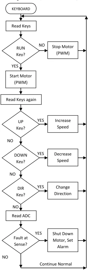
Figure 5: The System Control Software Flowchart
V. EXPERIMENTAL RESULTS
A) Motor Tests
[image:5.612.323.566.233.388.2]Initially a single motor is tested with the actual drive and the voltage across the motor (Vm VDC) and that across the sense resistor (Vs mV DC) are plotted against the PWM Duty cycle (pulse width) variations. Figure 6 shows the PWM behavior curves.
Figure 6: Basic Motor Test against Pulse Width
It is observed that as the pulse width increases from 10% (20µs duration) towards 90% (180µS duration) the average voltage across the motor also increases which in turn increases the motor speed (rpm). This further increases the current through the motor and a proportionate increase in the sense voltage across the sense resistor is obsered. B) Multiple Motor Tests
Two different types of motor ratings were chosen. While the rated supply for these type is common of 6-15VDC, power, torque and speed in rpm were different. Three motor devices from each of the two types, giving a total of six motors were selected for tests. These motors were connected to the actual drive under ―no-load‖ condition and the voltage across the motor and the sense resistor due to motor current are plotted against the PWM Duty cycle (pulse width) variations. Table-II summarizes the Motor Specifications while figure 7 shows the test curves for Type 1 motor while figure 8 shows the tests for Type 2 motor.
KEYBOARD
Read Keys
RUN Key?
Stop Motor (PWM)
YES
NO
Start Motor (PWM)
Read Keys again
UP Key?
Increase Speed
DOWN Key?
Decrease Speed
DIR Key?
Change Direction
Fault at Sense?
Shut Down Motor, Set
Alarm Read ADC
YES
NO
YES
NO
YES
NO
YES
NO
International Journal of Emerging Technology and Advanced Engineering
Website: www.ijetae.com (ISSN 2250-2459, ISO 9001:2008 Certified Journal, Volume 6, Issue 1, January 2016)
[image:6.612.49.289.152.446.2]99
Table II
MOTOR TYPE SPECIFICATIONS
Parameter Motor Type 1 Motor Type 2
Supply Voltage
(VDC)
6-15 6-15
Power (W) 5.75 7.98
Speed (RPM) 10668 9869
Torque (g-cm) 58.8 78.4
[image:6.612.324.565.202.378.2]Rated Current (A) 0.77 0.99
Figure 7a: Motor Voltage against Pulse Width for Type -1 Motors
Figure 7b: Sense Voltage against Pulse Width for Type -1 Motors
It can be seen that for different devices under test (DUTs or motors in this case) the voltage applied to the motor against pulse width is in close agreement for all three motors. Therefore the performance and proper functioning of the motor drive system is validated.
[image:6.612.323.564.402.580.2]Figure 8a: Motor Voltage against Pulse Width for Type -2 Motors
Figure 8b: Sense Voltage against Pulse Width for Type -2 Motors
C) PWM Pulse Drive Tests
[image:6.612.48.289.465.645.2]International Journal of Emerging Technology and Advanced Engineering
Website: www.ijetae.com (ISSN 2250-2459, ISO 9001:2008 Certified Journal, Volume 6, Issue 1, January 2016)
100 The high voltage (+12V) level pulse output from the MOSFET that drives the actual motor is also monitored and the ―Rise‖ and ―Fall‖ time are observed on the DSO with its built-in parameter measurement feature. Figure 9 (d-e) shows the Rise time (Tr) and Fall time (Tf) measurement screen-shots.
Figure 9a: TTL PWM signal for 10% Duty Cycle
Figure 9b: TTL PWM signal for 50% Duty Cycle
[image:7.612.374.508.135.234.2]Figure 9c: TTL PWM signal for 90% Duty Cycle
Figure 9d: Rise Time on 12V MOSFET Pulse
Figure 9e: Fall time of the 12V MOSFET Pulse
VI. CONCLUSIONS
From the experimental results obtained it can be concluded that both direction and speed control of a DC motor can be achieved using a single microcontroller chip with Enhanced PWM capabilities without any additional hardware. Out of the several microcontroller ports, one is used to interface keyboard for user commands to activate
motor functions such as RUN/STOP,
FORWARD/REVERSE and SPEED +, SPEED – in a cost effective manner.
In cost sensitive applications where closed loop control is desirable but the cost is a limiting factor, control feedback in the form of current sensing resistor and a suitable amplifier can also be implemented to achieve both feedback control and fault detection.
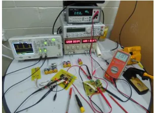
[image:7.612.79.255.203.650.2]Figure 10 (a-d) shows respectively the complete system, close-up view and the component and solder side of the motor drive.
[image:7.612.365.522.476.591.2]International Journal of Emerging Technology and Advanced Engineering
Website: www.ijetae.com (ISSN 2250-2459, ISO 9001:2008 Certified Journal, Volume 6, Issue 1, January 2016)
101
Figure10b: Close up look at the control system – Keyboard (Left), Microcontroller Board (Middle) and Motor Drive (Right) with the test
[image:8.612.94.246.134.256.2]motors in the background
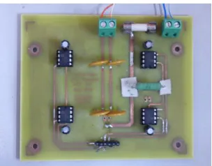
Figure 10c: Component Side (Top) View of the motor drive
Figure 10d: Solder Side (Bottom) View of the motor drive with the SMD components such as MOSFETs, DIODES, LEDs, Resistors and
Capacitors placed on this side
The system can be powered from a single 12V battery thus it becomes an ideal choice in applications such as modern robotic and Remotely Operated Vehicles (ROVs).
All the three major modules of the system such as the ―Keyboard‖, the ―Controller Board‖ and the ―Motor Drive‖ were fabricated on good quality glass-epoxy PCBs. The PCB layout was prepared in house by the author and the PCB laboratory of the school fabricated the PCBs.
All soldering of these boards including the Surface Mount Devices (SMDs) was also done in-house by the author.
The control software was also written by the author in assembly language using the MPLAB IDE from Microchip Technology Inc.
Acknowledgements
This research work is part of the Fiji National University (FNU) funded research project with Activity Code ACT-334. The author is thankful to the CRC and URPC Committee members for the kind approval of the research project and the research grants. Thanks are also due to the laboratory technicians who prepared the PCBs in short time and to the Procurement and Finance section of FNU for faster processing of the material requirements. The author is also thankful to the Head of School and the Dean for their constant support and encouragement to the staff members in carrying out the research work. Finally thanks are due to the unknown referees for their valuable suggestions in improving this manuscript.
REFERENCES
[1] Mike Rylee, 2014, ―Low-cost Bidirectional Brushed DC Motor Control Using PIC16F684‖, Microchip Technology Inc., Application Note AN893, ISBN 978-1-63276-321-1
[2] P.C. Sen, 1997, ―Principles of Electric Machines and Power Electronics‖, 2nd
Edition, John Wiley and Sons
[3] Muhammad H. Rashid, 2004, ―Power Electronics Circuits, Devices and Applications‖ 3rd Edition, Pearson Education, ISBN 978-81-317-0246-8
[4] Donald Richardson, Arthur J. Caisse Jr., 1997, ―Rotating Electric Machinery and Transformer Technology‖, 4th Edition. Prentice Hall. [5] Theodore Wildi, 2006, ―Electrical Machines, Drives, and Power
Systems‖, 6th Edition, Pearson Prentice Hall, ISBN 0-13-177691-6 [6] PIC16F877/A Microcontroller Datasheet, Microchip Technology
Inc., www.microchip.com
[7] PIC16F887 Microcontroller Datasheet, Microchip Technology Inc., ISBN 9781620766743
[8] IRF7425 MOSFET Datasheet, International Rectifier, www.irf.com [9] IRF7457 MOSFET Datasheet, www.irf.com
[image:8.612.93.245.294.413.2]