Distributed Control Scheme for Voltage Regulation
in Smart Grids
Amirhossein Sajadi
a*, Seyed Sina Sebtahmadi
b, Marcin Koniak
a,
Piotr Biczel
a, Saad Mekhilef
ba Institute of Electrical Power Engineering, Warsaw University of Technology, Koszykowa 75, Warsaw, 00-662, Poland b Department of Electrical Engineering, Faculty of Engineering, University of Malaya, Kuala Lumpur, 50603, Malaysia
Abstract
The current uncertainty about oil and gas prices and their resources, and future energy concerns, smart grids lead to further development. In this paper, a two way communication-based distributed control for voltage regulation in smart grid is proposed. Moreover, 16-bus distribution feeders system is modeled by real time simulation in MATLAB/Simulink in order to evaluate the effectiveness of the proposed scheme. The results are evidence for capability of proposed system to regulate the voltage in smart distribution feeders.
Keywords: Smart grids, voltage regulation, multi-agent systems
1.Introduction
A smart grid is the modernized and automated power delivery system. This definition means integrity of the existing conventional facilities and advanced power engineering, sophisticated sensors and monitoring technology, two ways communications, and distributed generation (DG) units [1],[2]. Therefore, the main part of these grids is integrating a wide variety of DG [3]. On the other hand, distribution systems are particularly designed to deliver the power to end user costumer excluding any DG. Hence, connecting the DGs in distribution level to power grid affects significantly on the flow of power and voltage conditions, either positive or negative [4]. The positive impacts can be: 1) voltage support, 2) loss reduction, 3) transmission systems and distribution systems capacity release, and 4) improved utility system reliability [5]. However, the operation of DG units connected to distribution grid, affects on voltage of generator terminal of connection bus [6]. According to rapid increasing penetration of DG units in power systems, this effect is becoming more and more significant and consequently nonlinear and unpredictable nature of renewable DG resources brings on more complexity [7].
Traditionally, the transformer tap-changers (LTC), the line regulators, and the shunt capacitors are placed at the substations and distribution feeders to provide the proper voltage regulation. Having many DG units connected among the loads on middle voltage or low voltage feeders makes the controlling of these devices quite convoluted [8].
In conventional power systems, the controlling whole entire system is accomplished by Supervisory Control and Data Acquisition (SCADA) [4],[5]. In recent years, multi-agent based systems have been developed to provide distributed control system for complex plants. A multi-agent based system is the combination of several agents working in collaboration together to achieve the overall goal of the system [9]-[11]. Therefore, a very well organized infrastructure consisting of hardware and software protocols is very essential to exchange the system status and control signals. In overall system, each control unit is
* Manuscript received June 14, 2012; revised August 6, 2012.
known as an agent and it interacts with other agents belonging to system via well defined communication language [9].
There have been significant works over the past few years about applying distributed control and multi-agent systems in power systems, with various applications such as perform power system diagnosis, power system restoration, power system secondary voltage control, and power system visualization.
In this paper, by considering the integration of previous works in this work, a proper distributed control for voltage regulation in smart distribution grid is presented. In order to reach this goal, a controller for distribution feeders consisting of LTC, DG, and load is designed. The rest of the paper is organized into six sections. Section II presents the proposed control scheme. Section III presents the study results; it includes modeling the proposed controller by a real time simulation in MATLAB SimulinkTM on 16-bus distribution feeders. The results illustrate how proposed control algorithm can regulate the voltage in the distribution grid. In addition, case result shows how the proposed controller can optimize the tap changer performance. Finally at section VI conclusion and recommendation close the paper.
2.Proposed Distributed Control Scheme
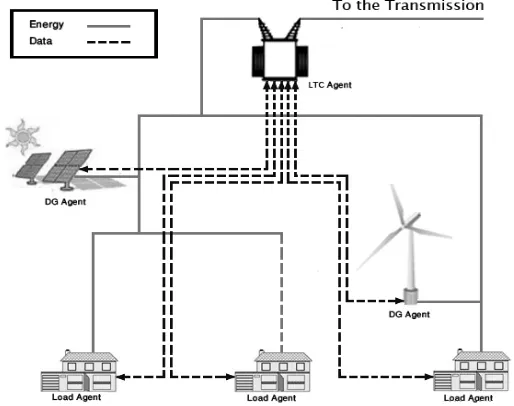
[image:2.595.169.426.384.587.2]The distributed controller structure consists of local control units which are known as agents and are independent functional modules operating on their own data and their operations can be affected by received messages from other agents. As well it can send message to other agents. The overall goal of entire system is to disassemble a complex system into some partial systems. The co-operation between agents, based on the exchanged messaged through a communication infrastructure, can solve convoluted problems.
Fig. 1. A conception of the proposed distributed control for future distribution systems.
According to this theory, proposed controller consists of different network components i.e. LTC, DGs, and loads and each of them has its own controller along with the capability to optimize its operation via local measurements and two ways communication acts. Fig. 1 shows a conception of the communication-based distributed controller for the future smart distribution systems.
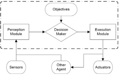
2.1. Interior Structure of Agents
Fig. 2. Proposed interior structure of a single agent.
2.2. LTC agent operation mechanism
Tap changer agent has two goals: the first one is keeping voltage in feeders within standard voltage range by changing transformer tap. The other one is minimizing number of tap changing operations to prevent excessive tap operation.
This agent receives critical sensed voltage deviation which has occurred at load points from load agent. Also, it receives permission messages which include voltage deviation at DG units coupling points to the grid, from DG agents. Furthermore, according to tap operations history, the agent estimates tap changer operation for upcoming time horizon. This estimation can be either offline or online depending on the available data. In this paper, we consider predicted tap changer operation is given data. Basically, this agent should comprise load deviation, DG deviation, and tap operation to find optimal operation point. Unlike DG agent, load agent has no capability to regulate the voltage. Therefore, always the load deviation must be considered in prior to DG deviation for making decision.
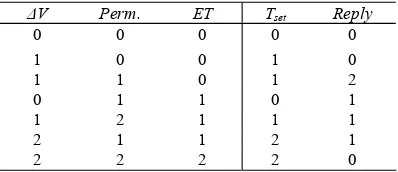
The LTC agent interpretation module sends three inputs to its decision maker. These inputs are ΔV
(voltage deviation at load points), Permission (from DG), and ET (predicted tap operation). The three variables have been coded as shown in Table 1. Although the inputs have been coded as crisp values in this work, these inputs could be represented as fuzzy sets by defining fuzzy membership functions.
The outputs of decision maker are Tset (set the tap) and Reply (send reply to permission) which have
been coded as shown in Table 2.
An expert-based decision making has been used in this work to map the inputs and outputs of the decision maker. If there is no permission message, tap changer performs in same way as a traditional voltage regulator does. It means if overvoltage or undervoltage happens and no permission message has been received, the agent sets the tap to go up or down according to voltage violation condition. Otherwise, in case of having voltage deviation at load points and permission message from DG, the LTC agent regulates the voltage based on load violation condition. Table 3 shows some of these rules and other similar rules are not shown due to the limit of pages.
Table 1. Codes of the input variables of the LTC agent
ET Perm.
ΔV Code
Tap<10 No message
Normal 0
10<Tap<20 Overvoltage
Overvoltage 1
Tap>20 Undervoltage
Undervoltage 2
Table 2. Codes of the output variables of the LTC agent
Reply Tset
Code
No Reply No Change
0
Accept Up
1
Reject Down
Table 3. Input-output mapping in the LTC decision maker Reply Tset ET Perm. ΔV 0 0 0 0 0 0 1 0 0 1 2 1 0 1 1 1 0 1 1 0 1 1 1 2 1 1 2 1 1 2 0 2 2 2 2
The execution module receives the decisions from the decision maker and executes them. When the tap should be changed, it performs just one tap change per each command. Also the Reply message will be sent to DG agent.
2.3. DG agent operation mechanism
Same as the LTC agent, DG agent has two goals. First, is to keep voltage of its feeder within standard voltage range. Second one is keeping generation of DG unit maximum. The level of deviation from maximum and minimum allowed voltage in the bus [12] at DG unit connection point is sensed by local measurement, if there is any. A module determines available reactive power of DG using following approach:
2 2
_ ( )
g av nom g g
Q = S − P −Q
where Snom is nominal total power of DG unit, Pg generating active power by DG unit, Qg is generating
reactive power by DG unit, and Qg_av total available reactive power by DG unit.
The DG agent interpretation module sends three inputs to its decision maker. These inputs are ΔV
(local voltage deviation), Qg_av (available reactive power), and Reply (from LTC). Table 4 shows these
three variable coding.
The outputs of decision maker are Permission (to LTC), Q_set (set the generated reactive power), and
P_set (real power curtailment) which have been coded as shown in Table 5.
[image:4.595.64.439.543.753.2]First we assume there is voltage deviation, so a permission message will be sent to tap changer. If reply is Reject, then operation point of DG unit will be maintained and it will continue power generating without any modification in settings. Otherwise, by using dQ/dV sensitivity factor and available reactive power, it can realize if DG controller can regulate voltage by modification of reactive power level or should curtail its generated real power using dP/dV sensitivity factor.
Table 4. Codes of the input variables of the DG agent
Reply Qg_av ΔV Code No Reply N/A Normal 0 Accept Low Overvoltage 1 Reject High Undervoltage 2
Table 5. Codes of the output variables of the DG agent
Pset Qset Permission Code MPPT No Change No message 0 Curtailment Lead Overvoltage 1 Curtailment Lag Undervoltage 2
Table 6. Input-output mapping in the DG decision maker
Table 6 shows some of input-output mapping that has been extracted using the expert-knowledge. Note that Qset and Pset cannot be activated at the same time. The execution module receives the decision
from the decision maker and executes that.
2.4. Load agent operation mechanism
The main task of load agent is measurement of bus voltage at load point. Its other task is to control the status of loads based on predefined priority to manage critical and-critical loads. In this paper just the first task is assigned to the load agent. Therefore, after getting information from the sensors, it compares them with maximum and minimum allowed voltage in the bus [12] to detect deviations from reference value, either overvoltage or undervoltage.
max ( m max), min ( min m)
V V V V V V
Δ = − Δ = −
In case of the normal operation, both of these two values should be positive. In case of overvoltage,
Vmax will be positive and in case of undervoltage, Vmin will be positive. Table 7 demonstrates applied
approach for detecting any voltage deviation. However, as this agent has no executive task, therefore there is no need to any mapping table.
Table 7. Applied approach for voltage deviation detection
ΔVmin
ΔVmax
Condition
Negative Negative
Normal
Negative Positive
Overvoltage
Positive Negative
Undervoltage
3.Simulation Results and Discussion
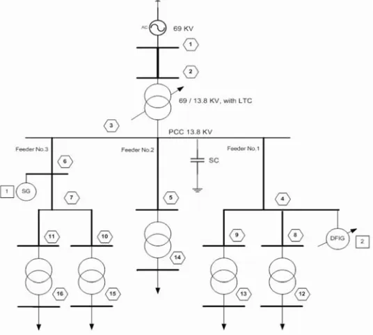
The 16-bus distribution feeders [13] shown in fig. 3 has been used to investigate the performance of the proposed two way communication-based distributed voltage regulation approach. The test system has been implemented in MATLAB SimulinkTM.
[image:5.595.165.433.503.744.2]The test system includes two DG units and a LTC transformer in substation. A 69/13.8 kV transformer with 32 taps is modified as LTC transformer. One of the DG units is dispatchable and it is modeled as a 1.5 MVA synchronous machine connected to bus 6. The other one is renewable-energy unpredictable source and it is modeled as a 6 MVA DFIG wind turbine connected to bus 4.
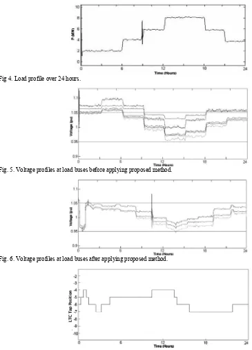
Fig. 4 shows the test system load profile over 24 hours. The minimum load is 2 MW and its maximum is 8 MW. In addition, at 6:00, 9:00, and 12:00 consumption increases and at 18:00 and 21:00 it decreases.
Fig. 5 shows the voltage profile at different load buses when the LTC performing based on the traditional local control. As it is shown, when the system works with traditional control techniques, three load buses have overvoltage condition during first 9 hours. Moreover, voltage profiles at load points are following proportionally load profile.
The Fig. 6 illustrates the capability of proposed control method in voltage regulation at load points over 24 hours. As is shown, at beginning of the day overvoltage is recorded load points. But tap changer operates and regulates the voltages in the feeders, consequently. In addition, at almost 10:30 switching of the capacitor into the network is the reason for voltage overshoot. In sum, voltage magnitudes at load buses are kept within standard range properly along with smoother voltage profiles.
Fig 4. Load profile over 24 hours.
Fig. 5. Voltage profiles at load buses before applying proposed method.
[image:6.595.67.432.240.747.2]Fig. 6. Voltage profiles at load buses after applying proposed method.
Fig. 7 shows the LTC operation along the 24 hours. Twelve tap operations are performed which is an acceptable number.
4.Conclusion and Future Work
The smart grid technologies such as two ways of communication will facilitate the application of multi-agent control in future active distribution networks. In this paper a two way communication-based distributed control for voltage regulation in smart distribution grid have been proposed. The proposed system consists of LTC agent, DG agents, and load agents. In order to investigate capability and applicability of proposed scheme a real time simulation has been done. The results are the evidence of capability and superiority of the proposed multi-agent control structure in acceptable regulating the voltage by keeping voltage within standard range during 24 hours. Distributed measurements by placing sensors at load points and communication with LTC were applied. Also the collaboration between agents optimized performance of the tap changer.
In the future work another specific scenario will be considered such as when the LTC agent sends a negotiation message to other DG agents when reply message carries Reject response in order to regulate voltage of target point by changing level of reactive power injection or consumption of them. In this case, active power generation will be kept in maximum level.
Acknowledgements
The authors would like to thank Ministry of Higher Education of Malaysia and University of Malaya for providing financial support under the research grant No.UM.C/HIR/MOHE/ENG/16001-00-D000024.
References
[1] Brown RE. Impact of smart grid on distribution system design. In: Proc. 2008 IEEE Power and Energy Society General Meeting, 2008:1-4.
[2] Moslehi K, Kumar R. A reliability perspective of the smart grid. IEEE Transactions on Smart Grid, 2010; 1(1):57-64. [3] Ipakchi A, Albuyeh F. Grid of the future. Power and Energy Magazine, IEEE, 2009; 7(2):52-62.
[4] Reigh RA, Saint R, Dugan RC, Burke J, Kojovic LA. Summary of distributed resources impact on power delivery systems. IEEE Transactions on Power Delivery, 2008; 23(3):1636-1644.
[5] Chiradeja P, Ramakumar R..An approach to quantify the technical benefits of distributed generation. IEEE Transactions on Eneregy Conversion, 2004; 19(4):764-773.
[6] Chang J, Jia S. Modeling and collaboration of wind-solar power generation system based on multi-agent system. In: Proc. IEEE International Symposium on Industrial Electronics, 2009:1403-1406.
[7] Carvalho PMS, Correia PF, Ferreira LAF. Distributed reactive power generation control for voltage rise mitigation in distribution networks. IEEE Trans. Power Syst., 2008; 23(2):766-772.
[8] Walling RA, Saint R, Dugan RC, Burke J, Kojovic LA. Summary of distributed resources impact on power delivery systems. IEEE Trans. Power Del., 2008; 23(3):1636-1644.
[9] Pipattanasomporn M, Feroze H, Rahman S. Multi-agent systems in a distributed smart grid: design and implementation. In: Proc. IEEE/PES Power Systems Conference and Exposition, 2009:1-8.
[10] Chang J, Jia S. Modeling and collaboration of wind-solar power generation system based on multi-agent system. In: Proc. IEEE International Symposium on Industrial Electronics, 2009:1403-1406.
[11] Manickavasagam K, Nithya M, Priya K. Control of distributed generator and smart grid using multi-agent system. In: Proc. 1st International Conference on Electrical Energy Systems (ICEES) 2011, 2011:212-217.
[12] Nguyen PH, Myrzik JMA, Kling WL Coordination of voltage regulation in active networks. In: Transmission and Distribution conf. and Exposition, 008:1-6.