© 2016, IRJET | Impact Factor value: 4.45 | ISO 9001:2008 Certified Journal
| Page 1221
BER PERFORMANCE IMPROVEMENT FOR 4 X 4 MIMO SINGLE CARRIER
FDMA SYSTEM USING MMSE EQUALIZATION
Sharmila S
1, Shanthi T
21
PG student, ECE(VLSI Design), Kings College of Engineering, Tamil Nadu, India
2
Head of Department, ECE, Kings College of Engineering, Tamil Nadu, India
---***---Abstract -
The main objective of this project is to design a soft decoding scheme to improve the Bit Error Rate (BER) in the MIMO SC-FDMA uplink transmission. The Long Term Evolution Advanced (LTE-A) uplink transmission is covered as the main topic in this report.This project mainly focuses on the uplink transmission i.e., from Mobile to base station transmission. The main focus is on the single-carrier frequency division multiple access (SC-FDMA) scheme which has been selected as the multiple-access scheme of the LTE uplink. It also employs Multiple-Input Multiple-Output (MIMO) because wireless communication using MIMO links has emerged as one of the most significant breakthroughs in modern communications because of the huge capacity and reliability gains promised even in worst fading environment. The proposed system describes the basic ideas of the MIMO SC-FDMA transmission systems and focused and investigated the BER performance of the Rayleigh wireless channel under 16 QAM ( Quadrature amplitude modulation) modulation. Minimum Mean Square Error (MMSE) equalization is performed in the receiver side for better MIMO data detection. All analysis was performed under ideal fading conditions by the use of MATLAB which relates the SNR and the error performance of MIMO SC-FDMA systems. All the results obtained are simulated by using the MATLAB, under Rayleigh channel conditions. The BER performance of the proposed system is compared with the Orthogonal Frequency Division Multiple Access (OFDMA) MIMO systems which shows better results for SC-FDMA. Thus the software implementation of this MIMO SC-FDMA detector results in decreasing BER with increasing SNR.
Key Words:
SC-FDMA, MIMO, LTE-A, MMSE.
1.
INTRODUCTION
LTE-A is a 4th generation mobile telecommunication technology- 4G (International Mobile Telecommunications Advanced (IMT Advanced) project. LTE-A was finalized by the 3rd Generation Partnership Project (3GPP) in March 2011. LTE-A is not a completely new technology, rather it is an enhancement to LTE. The main objectives of LTE-A is to increase the peak data rate to 1 Gbps on the downlink and 500 Mbps on the uplink, improve spectral efficiency from a maximum of 16 bps/Hz in R8 to 30 bps/Hz in R10, increase the number of simultaneously active subscribers, and improve performance at cell edges. Many technologies employed in LTE continue to be used in LTE-A, such as orthogonal frequency division multiplexing (OFDM), OFDMA, MIMO, and SC–FDMA. Some of the difficulties encounter in the uplink of LTE-A are: 1) A problem encountered in the design of receivers for LTE-A communication systems is the detection of data from noisy measurements of the transmitted signals. 2) Because of OFDM’s high PAPR (peak to Average Power Ratio) and related loss of efficiency, an alternative to OFDM was desirable for the LTE uplink. 3) High rate of errors per bit. 4) Inefficient performance of modulation schemes such as BPSK, QPSK, and 8-PSK.
The main goal of this project is to deliver data with less BER for SC-FDMA LTE-A system. The bit error ratio (BER) is the number of bit errors divided by the total number of transferred bits during specified time interval. Some solutions for the above problem are: 1) Instead of OFDMA, SC-FDMA becomes a suitable scheme for the LTE uplink because of its low PARP. Also MIMO technology gains attention in wireless communications, because it offers significant increases in data throughput and link range without additional bandwidth or transmit power. 2) 16 QAM modulation scheme transmits 4 bits per symbol efficiently. 3) The FDE equalization technique i.e., MMSE decreases BER.
2.
ARCHITECTURE OF MIMO SC-FDMA SYSTEM
2.1
TRANSMITTER
© 2016, IRJET | Impact Factor value: 4.45 | ISO 9001:2008 Certified Journal
| Page 1222
[image:2.595.39.262.148.272.2]transmitted through the radio channel. To do so many signal process operations are required which as listed below.
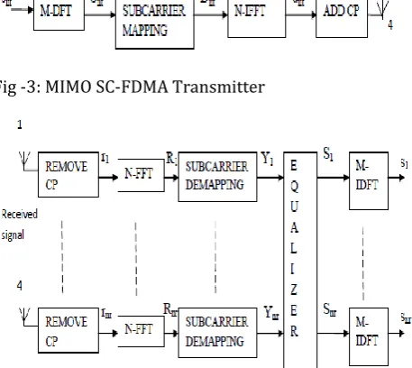
[image:2.595.40.269.237.441.2]Fig -3: MIMO SC-FDMA Transmitter
Fig -4: MIMO SC-FDMA Receiver
First the data symbols are modulated by a base band modulator to form a sequence of modulated complex symbols. LTE uses an adaptive base band modulation scheme so depending upon the channel it will adopt the modulation formats. The common modulation being used in LTE are Quadrature Phase Shift keying (QPSK), Binary Phase shift Keying (BPSK), 16 level Quadrature amplitude modulation (16-QAM) and 64-QAM. The next step is to convert the serial modulated data into N parallel data streams or group the data into blocks of N modulated symbols.
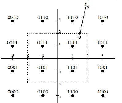
Figure -5: 16-QAM Constellation
Then it performs an M point Discrete Fourier Transform (DFT), this step will transform time domain modulated symbols to frequency domain symbols. Nt ranges from 1 to 4. The next step is sub-carrier mapping which maps M DFT output symbols to one of N orthogonal sub-carriers. N is the number of orthogonal frequency sub-carriers, which is greater than M, and M should be an integer multiple of N so that N=M*Q where Q is the bandwidth expansion factor or maximum number of users that can be supported by a system. As an example, if M=64 and N=256 then Q=4 so the maximum number of user that can be supported by the system simultaneously are four. The result of sub-carrier mapping is a set of complex symbols. There are two main types of mapping schemes that a SC-FDMA system can adopt, one is distributed and the other is localized.
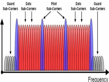
1) Localized Scheme: In a localized scheme each user uses a set of adjacent subcarriers to transmit its data. This means for localized SC-FDMA (LFDMA) only a fraction of the total bandwidth is used by one user. The advantage of LFDMA is that it achieves multi user diversity in frequency selective channel if each user is assigned subcarriers that have high channel gain. The disadvantage of this scheme is that it eliminates the chance of getting frequency diversity in the channel. It also requires channel state information (CSI) to map the data into the best adjacent symbols. 2) Distributed Scheme: In a distributed scheme the subcarriers used by a user are spread over the entire bandwidth. Since the information is spread it provides inherent frequency diversity. One of the common versions of distributed schemes is Interleaved SC-FDMA (IFDMA) in which the subcarriers that are assigned to terminals are equaled distant to each other. The disadvantage of this scheme is the losing user diversity. An example of SC-FDMA transmit symbols in the frequency domain is shown in figure 6. Let consider N= 4 subcarriers per user, Q = 3 users, and M = 12 subcarriers in the system. where
Xl,Distributed = transmit symbols for distributed subcarrier mapping scheme.
Xl,Localized = transmit symbols for localized subcarrier mapping scheme.
© 2016, IRJET | Impact Factor value: 4.45 | ISO 9001:2008 Certified Journal
| Page 1223
Instead of IDFT, Inverse FFT (IFFT) is performed which transforms complex frequency domain symbols to time domain signal more efficiently. Then each symbol is modulated by a single high frequency carrier and transmitted sequentially. If M=N then one can skip the DFT, frequency Mapping and IFFT blocks and direct modulated our time domain complex symbols to a single frequency.
[image:3.595.36.258.309.476.2]After that the Cyclic Prefix (CP), also called guard interval, will be added. The CP means prefixing symbols with a copy of the end of the symbol as shown in figure 7. The CP has two purposes here, the first is that it is use as a guard interval to eliminate the Inter Symbol Interference (ISI) from the previous symbol. The second is that prefixing the symbols with repetition of the end makes symbol periodic and linear convolution with channel will changes to circular convolution.
Fig -7: CP addition to data subcarriers
In frequency domain it is equivalent to point-wise multiplication of symbols to channel frequency response. To ease equalization, the length of CP should be minimum equal to maximum delay in the channel or in other words equal to the delay spread of the channel. Before modulating the signal with high frequency to transmit there is a pulse shaping filter that will shape the signal to get the desired spectrum.
2.2 RECEIVER
At the receiver side exactly the inverse of transmitter data transmission is performed. First demodulation of signal is performed after that removal of CP takes place since CP is an overhead it should be as optimized as possible. After removing the CP the receiver transform the received signal into frequency domain with the help of FFT. Nr ranges from 1 to 4. It then de-maps the sub carriers and then performs frequency domain equalization.
Normally the most common equalizer used is minimum mean square error (MMSE) frequency domain equalizer. The equalized signal is then transformed to time domain by IDFT and detection is done in time domain.
2.2
MIMO DETECTION
A MIMO detector which is used for detecting receive symbols, corresponds to symbols transmitted through transmit antennas from receive signals, when the transmit data transmitted by the terminal group are received through receive antennas. In MIMO detection the detector calculates an estimate of the transmitted signal as an output of the detector based on the received signal and the estimated channel matrix. After estimating and calculating the channel matrix, the LTE-A system recovers the transmitted signal from the received signal as an output of the detector. Modern silicon technology allows detectors to take full advantage of constrained maximum likelihood (ML) search techniques, and can calculate a posteriori probability (APP) soft information based on the received symbols. ML search is the optimum detection method and minimizes the bit error rate (BER). In general, the detection algorithm can be classified into three types:
Linear equalization algorithms Non linear equalization algorithms Optimal detection algorithms
Linear equalization algorithms include zero forcing (ZF) and MMSE algorithms. Of these, ZF is the simplest detection algorithm with the lowest computational complexity. MMSE is a high complexity algorithm, but offers high performance. Optimal detection algorithms include maximum likelihood (ML) and sphere decoding. These have preferable performance, but have the highest complexity. Non linear equalization algorithms include Successive interference cancellation (SIC), Parallel interference cancellation (PIC),Vertical Bell labs layered space time (V-BLAST) and QR decomposition algorithms. They have lower complexity and better performance than the optimum detection algorithms. The ZF receiver completely nulls out the influence of the interference signals coming from other transmit antennas and detects every data stream separately. The disadvantage of this receiver is that due to cancelling the influence of the signals from other transmit antennas, the additive noise may be strongly increased and thus the performance may degrade heavily. Thus among these algorithms linear equalization algorithm i.e. MMSE provides high performance and hence MMSE algorithm is used in this LTE-A system.
2.4 MMSE EQUALIZATION
© 2016, IRJET | Impact Factor value: 4.45 | ISO 9001:2008 Certified Journal
| Page 1224
domain equalizers, zero-forcing and MMSE equalizer are simplestones.
MMSE equalizer has better performance than zero forcing equalizer and is easy to implement. There are some equalizers belong to the third type. MMSE equalizer is a type of equalizer operating in both time and frequency domains. This equalizer can achieve a better BER performance with much higher algorithmic complexity. Because of its simple architecture and relatively good performance, frequency domainMMSE equalizer is chosen in our implementation. MMSE equalizer minimizes the mean square error between its output and the symbols transmitted from the transmitter. Also MMSE equalizer effectively minimizes the bit error rate compared to other types of equalizers.
3. MATHEMATICAL MODEL
3.1 MATHEMATICAL ANALYSIS OF MIMO SC-FDMA DATA TRANSMISSION
The data stream on each transmit antenna is grouped into blocks of M symbols, as follows:
SkNt(t)= [SkNt(0), SkNt(1),… SkNt(M-1) ]T
Where T = represents the transpose operation, Nt = the antenna index, M = DFT size, and SkNt(t) = represents the data on the transmit antenna for user, whose elements are chosen from quadrature amplitude modulation (QAM)constellation. Using the localized sub-carrier allocation scheme, the DFT outputs are mapped to M sub-carriers allocated to each user to produce DkNt(t). The localized sub-carrier mapping matrix for user is denoted by
TkN,M= [0M*(K-1)M, IM, 0M*(N-Km) ] T
Where IM is an M-dimensional identity matrix. The resulting FD SC-FDMA signal, Dknt(t), is transformed into the time-domain (TD) through an -point inverse fast Fourier transform (IFFT) operation, resulting in the TD signals as follows.
DkNt(t)= F-1N TkN,M FM SkNt(t)
Where FM is the normalized M-point DFT matrix F -1N is the normalized N-point IFFT matrix. Finally, a cyclic prefix (CP) is inserted and the final SC-FDMA signal is ready for transmission.
After the CP removal on antenna Nr at the SC-FDMA receiver with receive antenna, the received signal is denoted as
RNr =
t M nt Kk 1 1
hkNr,nt
DkNt(t)+ wnrwhere
= N -point circular convolution,WNr represents the additive white Gaussian noise (AWGN) on antenna ,
hkNr,Nt is the channel impulse response (CIR) between the transmit antenna and the receive antenna for user . The channel response can be formulated as follows.
H= 44 43 42 41 34 33 32 31 24 23 22 21 14 13 12 11 h h h h h h h h h h h h h h h h
HkNr,Nt=
1 0 N nhkNr,Nt[n] e-2πkn/N
hkNr,Nt= 1/M [
1
0 M
n
HkNr,Nt[k] ]e-2πkn/N
Using an N–point fast Fourier transform (FFT) and performing the sub-carrier de-mapping, the FD signal of user , received at antenna nr is denoted as
YkNr= [TkN,M ] T FN rNr
The received signals are combined using the Minimum Mean Square Equalizer. The equalized signal is then transformed to time domain by IDFT and detection is done in time domain. Multiple couples of data such as
𝑥0,𝑥1,…,𝑥3 are transmitted through different antenna respectively and the received signals are 𝑦1,𝑦2,…,𝑦4. Then,
the relationship between transmitted and the received data through the antenna configuration is as follows:
𝑦1=ℎ11𝑥0+ℎ12𝑥1+ℎ13𝑥2+ℎ14𝑥3+𝑧1
𝑦2=ℎ21𝑥0+ℎ22𝑥1+ℎ23𝑥2+ℎ24𝑥3+𝑧2
𝑦3=ℎ31𝑥0+ℎ32𝑥1+ℎ33𝑥2+ℎ34𝑥3+𝑧3
𝑦4=ℎ41𝑥0+ℎ42𝑥1+ℎ43𝑥2+ℎ44𝑥3+𝑧4
[image:4.595.308.507.462.630.2]MMSE equalization is performed at the receiver by
s=arg min||Hs-Y||2 +||σs||2
where σs = Inverse SNR of the transmitted signal
Fig -8: Signal detection in QAM constellation
© 2016, IRJET | Impact Factor value: 4.45 | ISO 9001:2008 Certified Journal
| Page 1225
points in the left half plane should be the distance between s and the 4 points which is the second column of the 8 points, these 4 points are denoted by α2 . Similarly the minimum distances between s and the 8 points in the right half plane should be the distance between s and the 4 points which is the first column of the 8 points in the right half plane, these 4 points are denoted by α3. The 2nd, 3rd and 4th digit can be estimate in the similar way.
4.
RESULT AND DISCUSSION
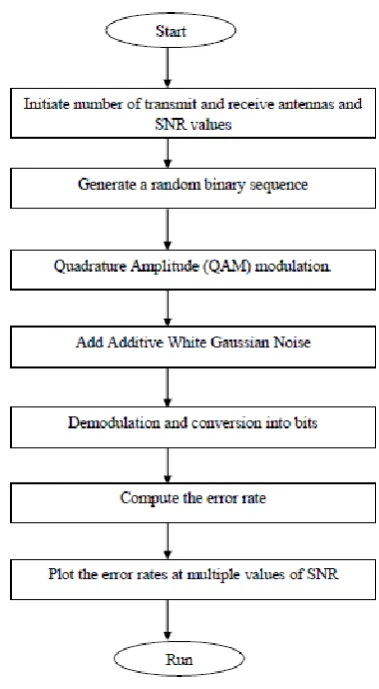
This chapter describes the software requirements, parameters and simulation procedures to evaluate the BER performance in MATLAB R2011a. Table -1: Simulation parameters
PARAMETER VALUE
DFT Size 512
Number of symbols 128 Signal constellation QAM
Bandwidth 20 MHz
Guard interval length 16
SNR 0 to 30 db
Subcarrier mapping Localized mode Antenna configuration MIMO
Number of base station
antennas 4
Number of UE antennas 4
Equalizer MMSE-FDE
In this section, the simulation results are presented for error rate analysis, which helps to characterize the behavior of different fading channels. The SNR and BER can be calculated as follows.
[image:5.595.318.508.102.447.2]SNR= 10log10 [signal power/ noise] BER = no. of errors / total number of bits send
Fig -9: simulation flow chart
The BER and SNR performance of the proposed and the base (existing) architecture for a 4x4 MIMO detector, with one resource block allocated to each user was evaluated through MATLAB simulations.
0 5 10 15 20 25
0 0.01 0.02 0.03 0.04 0.05 0.06
SNR in DB
E
R
R
O
R
R
A
T
E
SYMBOL ERROR RATE vs SNR in DB
BASE PROP
© 2016, IRJET | Impact Factor value: 4.45 | ISO 9001:2008 Certified Journal
| Page 1226
0 5 10 15 20 25 30
10-300 10-250 10-200 10-150 10-100 10-50 100 1050
B
it
E
rr
o
r
R
a
te
[image:6.595.45.232.106.310.2]SNR, dB vs Bit Error Rate
Fig -11: SNR vs. Error rate
Figure 11 show decreasing BER with increased SNR –as would be expected i.e. at 5db the proposed (blue line) method shows improvement than the existing (red line) method. It indicates that at SNR~ 10db, the error rate of base paper is 0.024 and the error rate of proposed work is 0.02. Likewise at SNR~ 15db, the error rate of base paper is 0.036 and the error rate of proposed work is 0.03. The results clearly demonstrate that for 16 QAM modulation the MMSE detector are more efficient for MIMO SC-FDMA transmission systems.
1 1.1 1.2 1.3 1.4 1.5 1.6 1.7 1.8 1.9 2 101.692
101.694 101.696 101.698 101.7
SNR, dB
A
V
E
R
A
G
E
M
E
A
N
S
Q
U
A
R
E
D
E
R
R
O
R
SNR, dB vs Bit Error Rate
Theory
Fig -12: SNR vs. Average Mean Squared Error
The BER v/s SNR curves are plotted in logarithmic vertical scale by setting SNR along the x-axis and BER (or error probability) along the y-axis. The figure 12 shows that the average mean square error decreases linearly with the increasing SNR.
5.
CONCLUSION
This project gives a detailed overview of an MIMO SC-FDMA system and compared the data transmission accuracy with the OFDMA system and with frequency domain equalization (FDE) system. The ultimate goal of this project was fulfilled by proposing an entire work flow to optimize the BER performance of the required baseband signal processing. This work flow consisted mainly of three steps: a literature study, research and analysis of MIMO data transmission, and evaluation of a low BER MIMO SC-FDMA system using MATLAB R2011a. A soft decoding MIMO detector with reasonable complexity was implemented for a MIMO SC-FDMA coded system, resulting in a significant enhancement in the BER performance. The BER and error probability is analyzed by varying the SNR. The BER performance of the proposed detection scheme is close to ML detection while the reduction in the complexity is significant in large constellation sizes. The above results clearly demonstrate that the SNR values are found to be lower for MIMO detectors compared to other detector systems.
REFERENCES
[1] Bai W., Yan D., Xiao Y, and Li S. (2009), “Performance evaluation of MIMO SC-FDMA system with FDE receiver,” in Proc. Int. Conf. WirelessCommun. SignalProcess.(WCSP),pp.1–5.
[2] Dhivagar B., Kuchi K. and Giridhar K. (2013), “An iterative MIMO-DFE receiver with MLD for uplink SC-FDMA,” in Proc. Natl. Conf. Commun.(NCC),pp.1–4. [3] Liu X., He X., Ren W. and Li S. (2010), “Evaluation of
near MLD algorithmsin MIMO SC-FDMA system,” in Proc. Int. Conf. Wireless Commun.Netw. MobileComput(WiCOM),pp.1–4.
[4] Lim S., Kwon T., Lee J. and Hong D. (2010), “A new grouping-ML detectorwith low complexity for SC-FDMA systems,” in Proc. IEEE Int. Conf.Commun. (ICC),pp.1–5.
[5] Muhammed, M., Khalid, K., and Muhammed, U., (2012), “LTE-Advanced: Requirements and Challenges for 4G Cellular Network”, Journal of Emerging Trends in Computing and Information Science, 665-670.
[6] Neshatpour k. Mahdavi M. and Shabany M, (2012), “A low-complexityhigh- throughput asic for the sc-fdmamimo detectors,” in Proc. IEEEInt. Symp. (ISCAS),pp.3065–3068.
[7] Pan Z., Wu G., Fang S. and Lin D. (2010), “Practical soft-SIC detection for MIMO SC-FDMA system with
co-channel interference,” in
Proc.Int.Conf.WirelessCommun.SignalProcess.(WCS), pp.1–5.
[image:6.595.40.258.461.651.2]© 2016, IRJET | Impact Factor value: 4.45 | ISO 9001:2008 Certified Journal
| Page 1227
Innovative Technology and Exploring Engineering,102-104.
[9] Studer C., Fateh S. and Seethaler D. (2011), “ASIC implementation of soft-input soft-output MIMO detection using MMSE parallel interference cancellation,” IEEE Journal, Solid-State Circuits, vol. 46, no. 7, pp.1754–1765.