© 2015, IRJET ISO 9001:2008 Certified Journal Page 1302
Methodology for Crucial Data Processing in Cloud Computing
K. Siva Sankar
11
Assistant Professor, Noorul Islam University, Tamil Nadu, India.
---***---Abstract -
Bewitch opens a new door towards
the concepts of Infrastructure-as-a-Service
(IaaS) Clouds. The cloud computing companies
have processing frameworks designed for
static nature of the cluster environment.
Accordingly, the allocated compute resources
may be insufficient for big parts of the
submitted job and unnecessarily increase
processing time and cost. Bewitch facilitates
new ways of data processing in clouds. In this
paper we discuss the novel approach for
efficient parallel data processing in clouds
and present this work. Bewitch is the first data
processing framework to explicitly exploit the
dynamic resource allocation offered by today’s
IaaS clouds for both, task scheduling and
execution. Particular tasks of a processing job
can be assigned to different types of virtual
machines
which
are
automatically
instantiated and terminated during the job
execution.
Key Words:
Key word1, Key word2, Key word3, etc…
1. INTRODUCTION
Now-a-days many of the companies have to process vast amount of data in a cost-effective approach. The internet companies store and analyze massive data sets. These data sets are handled by traditional database solutions prohibitively expensive [1]. So several companies have to developed distribute data storage and large clusters of commodity servers. The tasks are split into several subtasks, distributed among the available nodes and computed in parallel [2]. In this manner many of these companies have also built own data processing frameworks. The best examples are Microsoft Dryad [3], Google’s MapReduce [4] and Mapreduce-Merge [5]. They can be derived from the functionality in many task computing (MTC) and high throughput computing (HTC), depending on the amount of data and the number of task involved in the computation [6].
Cloud computing has to change the current IT industry. For companies that only have to process large amount of data occasionally running their own data center is obviously not an option. Instead, cloud computing has emerged as a promising approach to rent a large IT
infrastructure on a short-term pay-per usage basics. Operators of IaaS clouds like Amazon EC2 [7], let their customers allocate access and control a set of virtual machines (VMs) which run inside their data centers and only charge them for the period of time the machines are allocated, the VMs are different types, each type with its own characteristics (number of CPU cores, amount of main memory) and cost.
Since the VM abstraction of IaaS clouds fits the architectural paradigm assumed by the data processing frameworks, projects like Hadoop [8], a popular open source implementation of Google’s MapReduce framework already begun to promote using their framework in the cloud. Recently Amazon has integrated Hadoop as one of its core infrastructure services. This framework embracing its dynamic resource allocation and the cloud to imitate the static nature of the cluster environment, they were originally designed for, e.g., at the moment the types and number of VMs allocated at the beginning of the compute job cannot be changed in the course of processing, although the job consists of completely different demands on the environment. As a result, rented resources may be inadequate for large parts of the processing job, which may lower the overall processing performance and increase the cost.
The paper focused on the framework is Bewitch. Bewitch is the first data processing framework to explicitly exploit the dynamic resource allocation for clouds both task scheduling and execution. Particular tasks of a processing job can be assigned to different types of virtual machines, which are automatically instantiated and terminated during the job execution. Bewitch does not consider resource overload or underutilization during the job execution automatically.
2. LITERATURE REVIEW
2.1 Parallel Data Processing with MapReduce: A Survey
© 2015, IRJET ISO 9001:2008 Certified Journal Page 1303
2.2 Adapting MapReduce for Dynamic Environments Using a Peer-to-Peer Model
To improve the master-slave architecture of current implementations to suitable for and P2P dynamic scenarios. P2P model to dynamically assign the master role and to manage master failures in a decentralized but simple way. In our P2P-MapReduce architecture, each node can act either as master or slave. The role assigned to a given node depends on the current characteristics of that node, and so it can change dynamically over time. Thus, at each time, a limited set of nodes is assigned the master role, while the others are assigned the slave role. Moreover, each master node can act as backup node for other master nodes. A user node can submit the job to one of the master nodes, which will manage it as usual in MapReduce. That master node check the status of the job on its backup nodes. In case those backup nodes detect the failure of the master, they will elect a new master among them and will restart the job from the latest available checkpoint. P2P-MapReduce architecture implemented by Sun’s JXTA P2P framework.
2.3 P2P-MapReduce: Parallel data processing in dynamic Cloud environments
The P2P-MapReduce framework exploits a peer-to-peer model to manage node churn, master failures, and job recovery. It provides dynamic Cloud infrastructures. P2P-MapReduce framework does not suffer from job failures even in the presence of very high churn rates. P2P-MapReduce adopts a peer-to-peer model in which a wide set of autonomous nodes (peers) can act either as a master or as a slave. At each time, a limited set of nodes is assigned the master role, while the others are assigned the slave role. The role assigned to a given node can change dynamically over time, so as to ensure the presence of the desired master/slave ratio for reliability and load balancing purposes. The data are moved across nodes using a file transfer protocol like FTP or HTTP.
2.4 Apache Hadoop:
Apache Hadoop is an open-source software framework that supports data-intensive distributed applications. It supports the running of applications on large clusters. The Hadoop framework transparently provides both reliability and data motion to applications. Hadoop implements a computational paradigm named map/reduce, where the application is divided into many small fragments of work, each of which may be executed or re-executed on any node in the cluster. In addition, it provides a distributed file system that stores data on the compute nodes, providing very high aggregate bandwidth across the cluster. Both map/reduce and the distributed file system are designed so that node failures are automatically handled by the framework. A small Hadoop
cluster will include a single master and multiple worker nodes. The master node consists of a JobTracker, TaskTracker, NameNode, and DataNode. A slave or worker node acts as both a DataNode and TaskTracker, though it is possible to have data-only worker nodes, and compute-only worker nodes.
3. IMPLEMENTATION
3.1 Bewitch Design
Bewitch is a new data processing framework for cloud environments. Bewitch takes up many ideas of previous processing frameworks but refines them to better match the dynamic and opaque nature of a cloud.
Architecture
Bewitch’s architecture follows a classic master-worker pattern as illustrated in Fig. 1.
Fig.1. Structure overview of Bewitch running in an Infrastructure-as-a-Service (IaaS) cloud.
© 2015, IRJET ISO 9001:2008 Certified Journal Page 1304 Bewitch job consists of is carried out by a set of
instances. Each instance runs a so-called Task Manager (TM). A Task Manager receives one or more tasks from the Job Manager at a time, executes them, and after that informs the Job Manager about their completion or possible errors. Unless a job is submitted to the Job Manager, we expect the set of instances (and hence the set of Task Managers) to be empty. The Job Manager then decides, depending on the job’s particular tasks, how many and what type of instances the job should be executed on, and when the respective instances must be allocated/deallocated to ensure a continuous but cost-efficient processing.
The newly allocated instances boot up with a VM image. The image is configured to automatically start a Task Manager and register it with the Job Manager. Initially, the VM images used to boot up the Task Managers are blank and do not contain any of the data the Bewitch job is supposed to operate on. As a result, we expect the cloud to offer persistent storage (like, e.g., Amazon S3 [9]). This persistent storage is supposed to store the job’s input data and eventually receive its output data. It must be accessible for both the Job Manager as well as for the set of Task Managers, even if they are connected by a private or virtual network.
3.2 Job Description
Job description to describe the Bewitch jobs that is similar to Microsoft’s Dryad [3]. Bewitch jobs are expressed as a directed acyclic graph (DAG). Each vertex in the graph represents a task of the overall processing job, the graph’s edges define the communication flow between these tasks. We also decided to use DAGs to describe processing jobs for two major reasons, the first reason is that DAGs allow tasks to have multiple input and multiple output edges. This tremendously simplifies the implementation of classic data combining functions like, e.g., join operations [5]. Second and important reason is DAG’s edges explicitly model the communication paths of the processing job. As long as the particular tasks only exchange data through these designated communication edges, Bewitch can always keep track of what instance might still require data from what other instances and which instance can potentially be shut down and reallocated [10].
Defining a Bewitch job comprises three mandatory steps. First, the user must write the program code for each task of his processing job or select it from an external library. Second, the task program must be assigned to a vertex. Finally, the vertices must be connected by edges to define the communication paths of the job. Tasks are expected to contain sequential code and process so-called records. From a programmer’s perspective records enter and leave the task program through input or output gates. Those input and output
[image:3.595.334.487.165.376.2]gates can be considered endpoints of the DAG’s edges. Regular tasks (i.e., tasks which are later assigned to inner vertices of the DAG) must have at least one or more input and output gates.
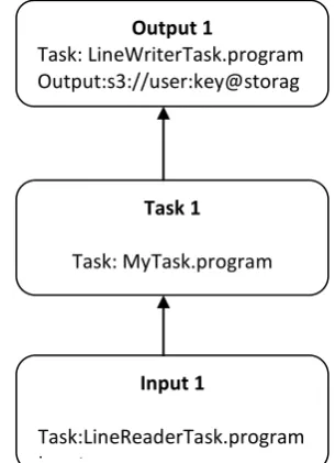
Fig. 2. An example of a Job Graph in Bewitch
After having specified the code for the particular tasks of the job, the user must define the DAG to connect these tasks. We call this DAG the Job Graph. The Job Graph maps each task to a vertex and determines the communication paths between them. The number of a vertex’s incoming and outgoing edges must thereby comply with the number of input and output gates defined inside the tasks.
Fig. 2 illustrates the simplest possible Job Graph. It only consists of one input, one task, and one output vertex. One major design goal of Job Graphs has been simplicity: Users should be able to describe tasks and their relationships on an abstract level. Therefore, the Job Graph does not explicitly model task parallelization and the mapping of tasks to instances. Once the Job Graph is specified, the user submits it to the Job Manager, together with the credentials he has obtained from his cloud operator. The credentials are required since the Job Manager must allocate/deallocate instances during the job execution on behalf of the user.
3.3 Job Scheduling and Execution
After having received a valid Job Graph from the user, Bewitch’s Job Manager transforms it into a so-called Execution Graph. An Execution Graph is Bewitch’s primary data structure for scheduling and monitoring the execution of a Bewitch job.
Unlike the abstract Job Graph, the Execution Graph contains all the concrete information required to schedule and execute the received job on the cloud. It
Output 1
Task: LineWriterTask.program Output:s3://user:key@storag e/output
Task 1
Task: MyTask.program
Input 1
Task:LineReaderTask.program Input:
© 2015, IRJET ISO 9001:2008 Certified Journal Page 1305 explicitly models task parallelization and the mapping of
[image:4.595.29.262.378.716.2]tasks to instances. The user has provided with his Job Graph, Bewitch may have different degrees of freedom in constructing the Execution Graph. Fig. 3 shows one possible Execution Graph constructed from the previously depicted Job Graph (Fig. 2). Task 1 is, e.g., split into two parallel subtasks which are both connected to the task Output 1 via file channels and are all scheduled to run on the same instance. Instead, its structure resembles a graph with two different levels of details, an abstract and a concrete level. While the abstract graph describes the job execution on a task level (without parallelization) and the scheduling of instance allocation/deallocation. It defines the mapping of subtasks to instances and the communication channels between them. On the abstract level, the Execution Graph equals the user’s Job Graph. For every vertex of the original Job Graph there exists a so-called Group Vertex in the Execution Graph. As a result, Group Vertices also represent distinct tasks of the overall job, however, they cannot be seen as executable units. The edges between Group Vertices are only modeled implicitly as they do not represent any physical communication paths during the job processing.
Fig. 3. An Execution Graph created from the original Job Graph.
Bewitch separates the Execution Graph into one or more so-called Execution Stages. An Execution Stage must contain at least one Group Vertex. Its processing can only start when all the subtasks included in the preceding stages have been successfully processed. Based on this Bewitch’s scheduler ensures the following three properties for the entire job execution: First, when the processing of a stage begins, all instances required within the stage are allocated. Second, all subtasks included in this stage are set up (i.e., sent to the corresponding Task Managers along with their required libraries) and ready to receive records. Third, before the processing of a new stage, all intermediate results of its preceding stages are stored in a persistent manner. The concrete level of the Execution Graph refines the job schedule to include subtasks and their communication channels. In Bewitch, every task is transformed into either exactly one, or, if the task is suitable for parallel execution, at least one subtask. For a task to complete successfully, each of its subtasks must be successfully processed by a Task Manager. Subtasks are represented by so-called Execution Vertices in the Execution Graph. To simplify management, each Execution Vertex is always controlled by its corresponding Group Vertex.
Bewitch allows each task to be executed on its own instance type, so the characteristics of the requested VMs can be adapted to the demands of the current processing phase. To reflect this relation in the Execution Graph, each subtask must be mapped to a so-called Execution Instance. An Execution Instance is defined by an ID and an instance type representing the hardware characteristics of the corresponding VM. It is a scheduling stub that determines which subtasks have to run on what instance (type). We expect a list of available instance types together with their cost per time unit to be accessible for Bewitch’s scheduler and instance types to be referable by simple identifier strings like “m1.small”. Before processing a new Execution Stage, the scheduler collects all Execution Instances from that stage and tries to replace them with matching cloud instances. If all required instances could be allocated the subtasks are distributed among them and set up for execution.
On the concrete level, the Execution Graph inherits the edges from the abstract level, i.e., edges between Group Vertices are translated into edges between Execution Vertices. In case of task parallelization, when a Group Vertex contains more than one Execution Vertex, the developer of the consuming task can implement an interface which determines how to connect the two different groups of subtasks. The actual number of channels that are connected to a subtask at runtime is hidden behind the task’s respective input and output gates. However, the user code can determine the number if necessary. Bewitch requires all edges of an Execution Graph to be replaced by a channel before processing can begin. The type of the channel determines how records are Input 1
(1) Stage 0 Stage 1
Output 1 (1)
Task 1 (2)
Execution Stage Group Vertex Execution Instance
Execution Vertex
Network Channel
File Channel ID:
i-40A608A 3 Type: m1.large
© 2015, IRJET ISO 9001:2008 Certified Journal Page 1306 transported from one subtask to the other. Currently,
Bewitch features three different types of channels, which all put different constrains on the Execution Graph.
Network channels: A network channel lets two
subtasks exchange data via a TCP connection. Network channels allow pipelined processing, so the records emitted by the producing subtask are immediately transported to the consuming subtask. As a result, two subtasks connected via a network channel may be executed on different instances. However, since they must be executed at the same time, they are required to run in the same Execution Stage. In-Memory channels, Similar to a network channel, an in-memory channel also enables pipelined processing. However, instead of using a TCP connection, the respective subtasks exchange data using the instance’s main memory. An in-memory channel typically represents the fastest way to transport records in Bewitch, however, it also implies most scheduling restrictions: The two connected subtasks must be scheduled to run on the same instance and run in the same Execution Stage. File channels: A file channel allows two subtasks to exchange records via the local file system. The records of the producing task are first entirely written to an intermediate file and afterward read into the consuming subtask. Bewitch requires two such subtasks to be assigned to the same instance. In general, Bewitch only allows subtasks to exchange records across different stages via file channels because they are the only channel types which store the intermediate records in a persistent manner.
4. PERFORMANCE COMPARISON
The results of performance comparison chart is taken three plots, that illustrate the average instance utilization over time ( the instance are broken down into the amount of time the CPU cores spent running the respective data processing framework (USR)), the kernel and its processes (SYS), and the time waiting for I/O to complete (WAIT). The network communication plots additionally show the average amount of IP traffic flowing between the instances over time.
The above chart shows the system utilization for executing the same MapReduce programs on top of Bewitch. For the first execution stage, corresponding to the map phase and reduce phase tasks, the overall resource utilization is comparable to the one of this chat.
Duringthe map phase and the reduce phase all six “c1.xlarge” instances show an average utilization of about 80 percent. However, after approximately 42 minutes, Bewitch starts transmitting the sorted output stream of each of the 12 Reduce subtasks to the two instances which are scheduled to remain allocated for the upcoming Execution Stages. At the end of Stage 0, Bewitch is aware that four of the six “c1.xlarge” are no longer required for the upcoming computations and deallocates them. Since
the four deallocated instances do no longer contribute to the number of available CPU cores in the second stage, the remaining instances again match the computational demands of the first step. During the execution of the 12 subtasks and the four Reduce subtasks , the utilization of the allocated instances is about 80 percent. The same applies to the final aggregation in the third Execution Stagewhich is only executed on one allocated “c1.xlarge” instance.
Fig.4. Comparison results of MapReduce and Bewitch
Fig.5. Comparison results of DAG and Bewitch
© 2015, IRJET ISO 9001:2008 Certified Journal Page 1307 in that period, the processing power allocated from the
cloud again fits the task to be completed. After 33 minutes, Bewitch has finished the entire processing job.
5. RESULT AND DISCUSSIONS
Bewitch has successfully allocated all instances required to start the first Execution Stage. Initially, the large tasks are splits into several subtasks. Then all the incoming records to sorting them. Here, the advantage of Bewitch’s ability to assign specific instance types to specific kinds of tasks. Until the end of the sort phase, Bewitch can fully exploit the power of the six allocated “c1.xlarge” instances. After that period the computational power is no longer needed for the merge phase. From a cost perspective it is now desirable to deallocate the expensive instances as soon as possible. In general, this transfer penalty must be carefully considered when switching between different instance types during job execution. For the future we plan to integrate compression for file and network channels as a means to trade CPU against I/O load. Thereby, we hope to mitigate this drawback. As a result, Bewitch automatically deallocates the six instances of type “c1.xlarge” and continues the next Execution Stage with only one instance of type “m1.small” left. Bewitch has finished the entire processing job and take the processing time is very short time period. So, Bewitch’s savings in time, cost and more complex processing jobs become feasible.
6. CONCLUSIONS
Our aim to present new framework for efficient parallel data processing, like Bewitch. Previously we have used Hadoop and Map Reduce framework for parallel data processing. But one drawback is, once VM is allocated at the beginning of a compute job cannot be changed in the course of processing. As a result, rented resources may be inadequate for big parts of the processing job, which may lower the overall processing performance and increase the cost. This drawback will be overcome used new framework is Bewitch. Bewitch can automatically allocate/deallocate virtual machines in the course of a job execution, can help to improve the overall resource utilization and, consequently, reduce the processing cost. When task manager have failed, at that time job manager allocate that task to another task manager. So each and every task is completed successfully. In general, we think our work represents an important contribution to the growing field of Cloud computing services.
REFERENCES
[1]. R. Chaiken, B. Jenkins, P.-A. Larson, B. Ramsey, D. Shakib, S. Weaver, and J. Zhou, “SCOPE: Easy and Efficient Parallel Processing of Massive Data Sets,” Proc. Very Large Database Endowment, vol. 1, no. 2, pp. 1265-1276, 2008.
[2]. B. Tierney, W. Johnston, H. Herzog, G. Hoo, G. Jin, J. Lee, L. Chen, D. Rotem, Distributed Parallel Data Storage Systems: A Scalable Approach to High Speed Image Servers, ACM Multimedia ‘94, San Francisco, Oct 1994. [3]. M. Isard, M. Budiu, Y. Yu, A. Birrell, and D. Fetterly, “Dryad: Distributed Data-Parallel Programs from Sequential Building Blocks,” Proc. Second ACM SIGOPS/EuroSys European Conf. Computer Systems (EuroSys ’07), pp. 59-72, 2007.
[4]. J. Dean and S. Ghemawat, “MapReduce: Simplified Data Processing on Large Clusters,” Proc. Sixth Conf. Symp. Opearting Systems
[5]. Design and Implementation (OSDI ’04), p. 10, 2004. [6]. H. chih Yang, A. Dasdan, R.-L. Hsiao, and D.S. Parker,
“Map- Reduce-Merge: Simplified Relational Data Processing on Large Clusters,” Proc. ACM SIGMOD Int’l Conf. Management of Data, 2007.
[7]. Raicu, I. Foster, and Y. Zhao, “Many-Task Computing for Grids and Supercomputers,” Proc. Workshop Many-Task Computing on Grids and Supercomputers, pp. 1-11, Nov. 2008.
[8]. Amazon Web Services LLC, “Amazon Elastic Compute Cloud (Amazon EC2),” http://aws.amazon.com/ec2/, 2009.
[9]. The Apache Software Foundation “Welcome to Hadoop!” http:// hadoop.apache.org/, 2009.
[10]. Amazon Web Services LLC, “Amazon Simple Storage Service,” http://aws.amazon.com/s3/, 2009.
[11]. D. Warneke and O. Kao, “Bewitch: Efficient Parallel Data Processing in the Cloud,” Proc. Second Workshop Many-Task Computing on Grids and Supercomputers (MTAGS ’09), pp. 1-10, 2009.