© 2015, IRJET ISO 9001:2008 Certified Journal Page 739
“THERMAL PERFORMANCE OF CLOSED LOOPS PULSATING HEAT PIPE AT VARIOUS
DIMENSION AND HEAT INPUT”
Prof. C.B.Kothare1 , Prof. K.S.Raizada2 ,Mr.Balu K.Chavhan3
1 Principal, Agnihotri School of Technology (Polytechnic) Wardha,
2Department of Mechanical Engineering S.S.P.A.C.E, Wardha, Rashtrasant Tukadoji Maharaj Nagpur University
3Student M.Tech. Heat power Engg, S.S.P.A.C.E, Wardha, Rashtrasant Tukadoji Maharaj Nagpur University
---***---Abstract
- Closed loop pulsating heat pipes (CLPHPs)are complex heat transfer devices having a strong thermo hydrodynamic coupling governing the thermal performance. Attempts are made to design, fabricate and test a closed loop pulsating heat pipe. In this experiment three different configurations of copper capillary tubes having internal diameters 1.5mm, 2.0 and alternate internal diameter 1.5mm and 2mm respectively. The total length of the closed loop pulsating heat pipe is 220 mm. The evaporator and condenser sections are 60 mm and 80 mm respectively. The experiments are conducted on vertical orientations for different heat loads varying from 10 W to 130 W in steps of 10 W. The PHP is tested on Ethanol, as working fluids for fill ratio viz. 50%, the temperature distribution across the heat pipe was measured and recorded using thermocouples. The performance parameters such as temperature difference between evaporator and condenser, thermal resistance and the overall heat transfer coefficient are evaluated. The experimental results demonstrate the heat transfer characteristics, lower thermal resistance and higher heat transfer coefficient of PHP are found to be better at a fill ratio of 50% for various heat input and also the thermal performance of set up C of pulsating heat pipe gives better result over the uniform diameter CLPHP.
KEYWORDS: Pulsating heat pipe, Fill Ratio, Working fluids.
1. INTRODUCTION
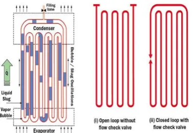
There is a vast requirement of miniature equipment in electronic devices for cooling purpose so pulsating heat pipe can significantly used for cooling purpose. Pulsating heat pipes (PHPs) or oscillating heat pipes (OHPs) are relatively young members in the family of heat pipes .The basic structure of a typical pulsating heat pipe consists of meandering capillary tubes having no internal wick structure. It can be designed in at least three ways:
a. Open loop system, b. Closed loop system and
[image:1.595.316.505.449.579.2]c. Closed loop pulsating heat pipe (CLPHP) with additional flow control check valve
Fig 1.1 Schematic of pulsating heat pipe and its design variations [Groll et al 2003]
© 2015, IRJET ISO 9001:2008 Certified Journal Page 740 are various parameters which affect the performance of
the closed loop pulsating heat pipe includes, i) Internal diameter of tube.
ii) Filling ratio of working fluid in tube. iii) Total numbers of turns.
iv) Input heat flux.
v) Device orientation
vi) Thermo-physical properties of the working fluid The closed passive system thus formed is evacuated and subsequently filled up partially with a pure working fluid, which distributes itself naturally in the form of liquid–vapour plug and slugs inside the capillary tube. One end of this tube bundle receives heat transferring it to the other end by pulsating action of the liquid vapour slug system. When the heat is supplied to the heat receiving portion (evaporator section) due to temperature difference their exist a temperature gradient which are responsible for the heat transfer. Due to supplied heat the vapour slug from due to low pressure side towards the heat radiating portion (condenser section) and again the liquid slug from the alternate cooling and heating are done. The generating and collapsing bubbles act as pumping elements transporting the entrapped liquid slugs in a complex oscillating–translating–vibratory fashion; a direct consequence of thermo-hydrodynamic coupling of pressure/temperature fluctuations with the void fraction (mal-) distribution.
There are various parameters which affect the performance of the closed loop pulsating heat pipe like orientation, internal diameter, length of tubes, flow of working fluid, numbers of tubes etc. The effect of varying diameter and flow patterns over a performance of closed loop pulsating heat pipe to enhance heat transfer coefficient is being principle candidate scrutinizes.
Pulsating heat pipe is miniature in size as well as more efficient than conventional PHP for cooling and thermal management.
2. EXPERIMENTAL SETUP AND PROCEDURE
2.1 INTRODUCTION
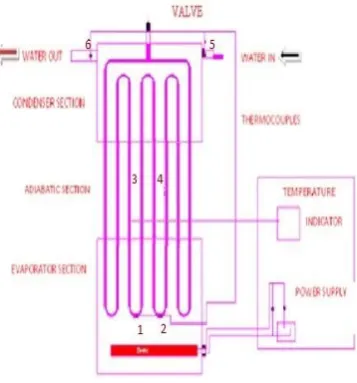
The experimental setup three kinds of configurations were designed for the PHPs. All three types of PHPs were made of copper capillary tubes. The tubes were bent into four turns with the bending radius of 10 mm, and joined end to end, forming an eight-channel serpentine loop. The total height of the closed loop pulsating heat pipe is 220 mm and total width 130mm. The evaporator, adiabatic and condenser section lengths are 60 mm, 80mm and 80 mm respectively. The valve for filling working fluid is arranged at the top of vertical tube of the PHPs, for the evacuation and filling assembly. The experimental setup consists of a closed loop PHP, temperature recorder, power supply unit, and water tank
cooling system for condenser. Both the evaporation and adiabatic sections were well thermally insulated by the proper insulation materials.
2.2 EXPERIMENTAL SETUP
[image:2.595.347.526.479.671.2]Fig. Shows the schematic diagram of the experimental setup. In this setup, copper is used as the capillary tube material in each section with inner diameter of different configuration having internal diameter 1.5mm, 2mm and alternate internal diameter, the outer diameter of 2.9mm, 3.6mm and alternate varying channel diameter respectively. In order to adiabatic section is connected between evaporator and condenser sections for a length of 80 mm. In the present investigation, the evaporator section consists of oil bath heater of 0-500 W is employed during the experiments for heating the working fluid. Six K type thermocouples are used for the temperature measurement. The operating temperature range of these K type thermocouples is 0 to 2400 °C. Two thermocouples are fixed in the evaporator section and two in condenser section, also two in adiabatic section similarly one in the oil bath and two are measured the inlet and outlet temperature of water at condenser section. The temperatures measured by two thermocouples in the evaporator section are named as T1 and T2. The temperatures measured by two thermocouples in the condenser section are named as T4, and T5 respectively.
Figure.2.1 Schematic diagram of experimental setup CLPHP
© 2015, IRJET ISO 9001:2008 Certified Journal Page 741 control panel. The experimental setup consists of a closed
loop PHP, temperature recorder, power supply unit, and water tank cooling system for condenser. Both the evaporation and adiabatic sections were well thermally insulated by the proper insulation materials. The heating power is provided by a carefully designed power supply unit. Heating was done by oil bath and cooling by water tank. The power meter measures the AC voltage, the current and the corresponding power simultaneously. The Filling Ratio was maintained at 30%, 50% and 70% for each configuration. The heating configuration was bottom heat orientation (+900). Six K-type thermocouples were attached to the wall of the PHP
.
2.3 EXPERIMENTAL DESCRIPTION
Figure. Shows the three kinds of configurations were designed for the pulsating heat pipe (PHPs). All the three types of the PHPs were made of copper capillary tubes are as follows.
1) The php in case A is normal php with a uniform inner diameter of 1.5mm
2) The php in case B is again normal with uniform internal diameter of 2mm
3) The php in case C is again normal with uniform internal diameter of 2mm
The differences among the three types of the PHPs lay on the variation in channel diameter along the flow path. 2.3.1 The PHP in case A is normal PHP with a uniform
inner diameter of 1.5mm
2.3.2 The PHP in case B is again normal with uniform internal diameter of 2mm:
These two configurations are fabricated by same procedure as follows,
Copper tubes are turn into U tube having 10mm radius according to length of evaporator and condenser i.e.60mm and 80mm these 8mm additional for fitting into acrylic plate. 8mm thick acrylic plate is used for baffle plate. The size of acrylic plate is 170*40*8mm.holes are drilled in to acrylic plate vertically accordingly internal diameter i.e. 1.5mm and 2mm. Holes are clean by using thinner.8mm counter bore are done as per external diameter of copper tube, Copper U tubes inserted into acrylic plate then sealed with araldite and M seal. While sealing care is taken about choking and leakage .then Condenser coil is fitted in to cooling bath and holes are sealed .two thermocouples are soldered in adiabatic section ,two thermocouples at inlet and outlet of the condenser And two at evaporator section.
2.3.3 PHP C is an alternate internal diameter of 1.5 and 2mm:
The PHP in case C were provided with some special configurations helpful to initiate and sustain the circulatory flow. For the PHP C, the inner diameter was designed to vary alternately. The inner diameters of the two adjacent tubes were 1.5mm and 2 mm respectively. These tubes joined end to end by soldering at refrigeration maintenance shop. Remaining procedure is same like other two configuration.3/4 inch valve is fitted at the top of each setup for evacuation and filling working fluid. The circulatory flow is desirable because the circulation of the working fluid enhances the capability for the working fluid to transport heat from the evaporation to the condensation zone.
In this study, one improved PHPs with special configurations, with alternately varying channel diameter, were designed and testified to be beneficial to forming and sustaining a circulatory flow. At 50% filling ratio vertically bottom heating mode are use.
2.4 HEATING UNIT:
The height of the evaporator section of the PHPs is 60 mm .Electrical heating oil bath is use to supply controlled uniform heating rates to evaporator coil. The size of the oil bath is 170*100*60mm. 1mm Sheet metal plates are used. Plates are cut in to required size and joined by using Araldite and sealing is done with M seal. Two holes are drill for inserting heater. 500W heater is used for heating oil. The evaporation sections were well thermally insulated by the proper insulation materials (Glass wool). Insulator to apply insulation to avoid heat loss. Dielectric oil is used for heating.
2.5 COOLING UNIT:
For the cooling of the condenser, cold water was circulated through the cooling bath. Cooling bath also made up of Acrylic plate having 3mm thickness. Size of cooling bath is 170*100*40mm. 5mm diameter inlet and outlet for cooling water, same diameter flexible transparent tube is used for water supply from tank and outlet also. Valve is arranged to regulate mass flow rate of water.
2.6 DATA UNIT:
© 2015, IRJET ISO 9001:2008 Certified Journal Page 742 condenser section (locations 5-6). All temperatures were
collected using digital temperature indicator. Dimmer stat, voltmeter and Ammeter are for power supply to heater regulating dimmer required wattage is provided to heating coil. Which shown by Voltmeter and Ammeter. Two in the condenser section (locations 5-6). All temperatures were collected using digital temperature indicator. Dimmer stat, voltmeter and Ammeter are for power supply to heater .regulating dimmer required wattage is provided to heating coil. Which shown by Voltmeter and Ammeter.
A series of experiments were performed on the three types of PHPs respectively, with various heat inputs from 10 to 140 W and different filling ratio 30%, 50% and 70% of total volumes. 50% volume of configuration A-4 ml, B- 6 ml and C- 8 ml Ethanol is used as the working fluid in the experiments. After evacuation up to 1kpa, ethanol fill in each setup and sealing is provided to valve. And setup is ready for testing.
Following procedure is adopted during the present transient and steady state experimentation:
Before filling the working fluid, air is blown inside the heat pipe to ensure that there is no fluid present inside the CLPHP.
CLPHP is filled with working fluid using a syringe for the required amount. The experiments are conducted for filling ratio 50%with three kinds of configuration respectively.
The CLPHP is oil bath heated with the help of a power supply by using heater 500W
The required amount of working fluid is then filled through a syringe by opening one end of the non-return valve such that the fluid directly enters the evaporator section.
Now the air is filled through the filling valve provided on the brass tube using another syringe.
The cooling water is allowed to the condenser section of PHP from the constant water bath and the amount of cooling water is controlled in such a way that the temperature rise of cooling water in the condenser is always between 10 C to 30 C.
The temperature data logger is then switched on to record the temperature readings.
The required wattage is set using the power supply unit. In the present work, the experiments were conducted by varying the heat inputs from 10W to 120W in steps of 10 W.
Also same time note temperatures at different locations by rotating knob on control panel for every wattage.
Repeat same procedure for other two configuration
3. RESULTS AND DISCUSSIONS
Experimental study on PHP indicated that three kinds of configuration is an important factor for the performance of PHPs. The result shows that, the thermal resistance decreases more rapidly with the increase of the heating power from 10 to 130W, whereas slowly decreases at input power above 80W. The thermal performance of set up C of pulsating heat pipe gives better result over the uniform diameter PHP with filling ratio i.e. 50%.The performance parameters of PHP like thermal resistance and heat transfer coefficient are would be evaluated for the above conditions. Working fluids are selected as ethanol. The graphs are plotted, in order to study, characteristics of the thermal resistance and average evaporator temperatures at different heat input for various internal diameter.
3.1 Effect of thermal resistance on the heat inputs in the CLPHP.
© 2015, IRJET ISO 9001:2008 Certified Journal Page 743 Fig. 3.1 Variation of thermal resistance over the
heat inputs CLPHP.
In case B the tube diameter is uniform 2.0mm. In which thermal resistance is lower than PHP A. working of PHP B is better than PHP A, up to 90W thermal resistance decline greatly and after that increase in heat input thermal resistance start to increase. Means there is a dry out condition start.
In case C the tube internal diameter is varying alternately as 1.5mm and 2.0mm. The PHP C with varying diameter has the most excellent thermal performance among them. Among three PHP C have low thermal resistance, it can work at higher heat input than other two uniform type configuration i.e. up to 110 W. in which circulatory flow are observed and remains in fixed direction which enhanced heat transfer coefficient. Due to alternate diameter vapor flow upward through 2mm diameter tube and come back through 1.5mm tube by gravity. After 120 W thermal resistance start increased and evaporator temperature also increase at fast rate because there is dry out condition initiated which near about stop the working of php.
[image:5.595.309.518.179.326.2]Efficiency comparison among three php is shown in fig 5.6 thermal resistance greatly affect on performance of php. In case php A highest value is 31% and it is in between 30 to 50 W after that start to decline.
In PHP B efficiency is better than php A it start to increase from initial and up to near about 90 W. after that descending up to dry out.
3.2 Effect of thermal efficiency on the heat inputs in the CLPHP
Fig. 3.2 Variation of efficiencies among three PHP.
In CLPHP C 1.5& 2mm alternate internal diameter are used whose efficiency is excellent than other two uniform configuration .it ascend from initially and maintained up to 110W. After that thermal resistance start to increases.
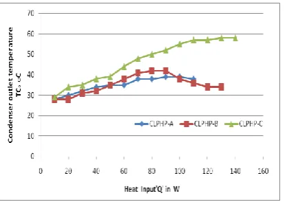
3.3 Effect of condenser outlet temperature on the heat inputs in the CLPHP
Fig 4.3 shows heat input verses condenser water outlet temperature in case a highest temperature gain is 39 oC at 80 W. In case B highest temperature gain is 42 oC at 90 W.
Fig. 3.3 Variation of condenser temperature among three PHP
And again in configuration C highest temperature achieved is 58oC at110 W in which from beginning higher the heat transfer coefficient and lower is the thermal resistance.
3.4 Thermal Resistance
The Thermal Resistance of PHP is given by Values of thermal resistance in present work are near about close to reference work. Various flow patterns, such as bubble-liquid slug flow, semi-annular flow andannular flow occur in different working conditions.
Q T T
R e c (K/W)
3.5 Effect of Heat Transfer Coefficient
The heat transfer coefficient of a PHP is given by [Faghri (1995)]
)
( e c
s T T
A Q h
(W/m 2 K)
4. CONCLUSIONS
In the present work, the experimental investigation on a closed loop pulsating heat pipe is carried out. The effects of heat input, working fluid, and alternate internal diameter on the performance of CPHP are studied.
Following conclusions are drawn from the present experimentation:
[image:5.595.37.274.504.653.2]© 2015, IRJET ISO 9001:2008 Certified Journal Page 744
Set up ‘A’ is having 1.5 mm uniform internal diameter
Set up ‘B’ is having 2 mm uniform internal diameter
Set up ‘C’ is having 1.5 mm and 2 mm alternate internal diameter.
1. The thermal performance of set up C of pulsating heat pipe gives better result over the uniform diameter PHP in the following parametric study.
Thermal resistance of PHP ‘C’ is less than uniform diameter PHP
Thermal efficiency of PHP ‘C’ gives better
efficiency over the uniform diameter PHP.
iii) The heat input of PHP increases the dry out zone of the uniform diameter PHP is above 80 watts. Whereas in PHP ‘C’ dry-out zone increases above 110 watts.
REFERENCES
1. Brian Holley, Amir Faghri,” Analysis of pulsating heat pipe with capillary wick and varying channel diameter. International journal of heat & mass transfer 48(2005)2635-2651
2. B.Y. Tong, T.N. Wong, K.T.Ooi, “Closed-loop pulsating heat pipe” Applied thermal engineering 21 (2001) 1845-1862.
3. Honghai yang Sameer Khandekar and Manfred Groll “operational characteristics of flat plate closed loop Pulsating Heat Pipe”13th International Heat Pipe Conference (13th IHPC), Shanghai, China, September 21-25, 2004.
4. Jian Qu a, Huiying Wua, Ping Cheng a, Xiong Wang, “Nonlinear analysis oftemperature oscillation in close loop pulsating heat pipe”. International journal of heat & mass transfer 52(2009)3481-3489.
5. J.L. Xu a, Y.X. Li a,b, T.N. Wong ,” High speed visualization of close loop pulsating heat pipe”. International journal of heat & mass transfer 48(2005)3338-3351
6. Khandekar S., M.Groll “Introduction to pulsating heat
pipe”; electronic cooling volume9 No2, may 2003 7. Niti Kammuang-Luea; Phrut Sakulchangsatjataia;
Pradit Terdtoona; D. Joseph Mookb, “Correlation to Predict the Maximum Heat Flux of a Vertical Closed-Loop Pulsating Heat Pipe” Heat Transfer Engineering, 30(12):961–972.
8. P. Charoensawan., S. Khandekar Manfred Groll, Pradit Terdtoon “Closed loop pulsating heat pipes Part A: parametric experimental investigations”. Applied Thermal Engineering 23 (2003) 2009–2020
9. P. Charoensawan, S. Khandekar Manfred Groll, Pradit Terdtoon “Closed loop pulsating heat pipes Part B: visualization & semi- empirical modeling”. Applied Thermal Engineering 23 (2003) 2021–2033
10. Shi Liu Jigtao Li Xiagum Dong. “Experimental study of flow patterns and improved configuration for pulsating heat pipe ” journal of thermal science 1003-2169(2007)01-0056-07
11. S. Khandekar, Nicolas Dollinger, Manfred Groll “Understanding operational regimes of closed loop pulsating heat pipes: an experimental study”. Applied Thermal Engineering 23 (2003) 707–719.
12. S. Khandekar Manfred Groll Institute for Kernenergetik und Energy system, University Stuttgart 70569 Stuttgart, Germany 5th Minsk International Seminars (Heat Pipes, Heat Pumps and Refrigerators), Minsk, Belarus, 2003.
13. Sameer Khandekar and Manfred Groll 9th International Heat Pipe Symposium, Kuala Lumpur, Malaysia, November 17-20, 2008.
14. Sameer Khandekar and Manfred Groll Roadmap to Realistic Modeling of Closed Loop Pulsating Heat Pipes49th International Heat Pipe Symposium, Kuala Lumpur, Malaysia, November 17-20, 2008
15. Sameer Khandekar and Manfred Groll On the definition of heat pipes: an overview Proc. 5th Minsk International Seminar (Heat Pipes, Heat Pumps and Refrigerators), Minsk, Belarus, 2003
16. Sameer Khandekar Prof. Dr.-Ing. Habil. M. Groll (2004) “thermo- hydrodynamics of closed loop pulsating heat pipe Institute for Kernenergetik and Energie systeme University Stuttgart.
17. Sameer Khandekar and Manfred Groll and vivak luckchoura “an introduction to pulsating heat pipe” electronic cooling volume 9 no.2 may 2003.
18. S. Khandekar (a), M. Groll (a), P. Charoensawan (b) and P. Terdtoon (b) Pulsating Heat Pipes: Thermo-fluidic Characteristics and Comparative Study with Single Phase Thermosyphons Proceedings of 12th International Heat Transfer Conference,Vol. 4, pp.459-464, Grenoble, France, 2002
19. Sanka VVSNS manyam and manmohan pandey.” Two-phase flow modelling in Closed Loop Pulsating Heat Pipes”13th International Heat Pipe Conference (13th IHPC), Shanghai, China, September 21-25, 2004.