© 2016, IRJET | Impact Factor value: 4.45 | ISO 9001:2008 Certified Journal
| Page 741
COMPUTATIONAL ANALYSIS OF NOTCHED FIN ARRAY USING NATURAL
CONVECTION
Sachin Kallannavar
1, Dr. U. C. Kapale
21
Student, Dept. of Mechanical Engineering, SGBIT Belagavi, Karnataka, India
2Professor, Dept. of Mechanical Engineering, SGBIT Belagavi, Karnataka, India
---***---Abstract -
A finite element method was adopted to study theeffect of various parameters on the convective heat transfer of notched fin array. The process parameters like fin spacing, depth of notch cut, percentage cut of notch, shape of notch etc. were considered for investigation. Aluminium and copper were used as specimen material for the fin during analysis. Simulations were carried out considering ANSYS 14.5 Fluent FEA tool. The analysis carried out for varying the fin spacing and optimum fin spacing of notch was observed at 10mm to 12mm spacing dimensions. Notched and unnotched fin array were simulated and the effect of notch on HTC of fin array was established. Further, the area removed for notch was compensated at top and bottom of the fin. The results indicate the better performance for area compensation at the top. It was also noted that the HTC increases with increase in percentage of cut and depth of cut of the notch. Investigation was extended to understand the effect of notch geometry. It was noted that the triangular notch is more effective than the rectangular and semicircular notch. Effect of angle for V-notch was considered for the analysis and it was observed that as angle increases the HTC decreases.
Key Words: Horizontal rectangular fin array (HRFA), Heat transfer coefficient (HTC), Fin spacing, Natural convection, Single chimney flow.
1. INTRODUCTION
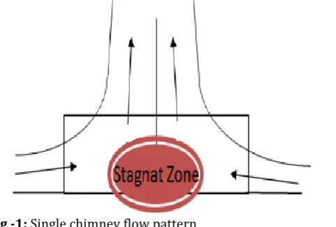
Fins are used to enhance the convective heat transfer in a wide range of engineering application. The convective heat transfer mainly depends on the heat transfer coefficient and surface area available for convection. Fins are commonly used for heat management in computer power supplies or substation transformers, internal combustion engine cooling (air cooled engines). Generally in natural convection heat transfer on horizontal fin array single chimney flow pattern is used for analysis. In this flow pattern the air enters from sideways and gets heated as it moves inwards (towards centre of the fin channel). As the temperature of the air increases air rises up due to decrease in density. Hence, no air comes in contact with the central bottom portion of the fin channel. This creates a stagnation zone near the central bottom portion of the fin channel as shown in Fig-1. To overcome this difficulty some portion of fin is removed near
the stagnation zone (notch), to increase the HTC. The notches are provided in various size and shapes, and are added at the place where fresh air comes in contact with the fin surface.
[image:1.595.317.558.603.766.2]Over the past few decades numerous investigations have been carried out on heat transfer and fluid flow characteristics in rectangular fins attached to horizontal and vertical surface in free environment [1-12]. S. G. Taji et.al [1] conducted experimental study on heated horizontal rectangular fin array under natural convection with variable fin spacing & heat loads and they concluded that the optimum fin spacing is around 10mm. Salila Ranjan Dixit et.al [2] carried out experimental study on notched and unnotched HRFA with variable fin spacing and they concluded that the performance of notched fin array is 30-50% superior than the corresponding unnotched array. G. P Lohar et.al [3] investigated HRFA for various fin spacing under natural and forced convection. The maximum HTC is observed for fin spacing 14-16mm under natural convection and 12-14mm in case of forced convection. S. D. Wankhede et.al [4] carried out experimental investigation on HRFA with and without inverted notch under natural and forced convection and concluded that as percentage cut of notch increases the HTC increases. Shivdas S. Kharche et.al [5] studied heat transfer analysis HRFA with and without notch and they observed that HTC of notched fin array is higher than unnotched fin array. Vishal Hegana et.al [6] reviewed and concluded that performance of notched fin array is superior to corresponding unnotched array. The present work addresses the investigation of HTC of HRFA by varying the geometric parameters of notch.
© 2016, IRJET | Impact Factor value: 4.45 | ISO 9001:2008 Certified Journal
| Page 742
2. Finite Element Analysis
[image:2.595.304.549.119.475.2]The CAD model of the HRFA is prepared in Catia V5 modeling environment as shown in Fig-2 and Ansys Fluent 14.5 simulation tool is used for the FE analysis. Generally fins are made of copper and aluminium alloys. The material properties adopted for analysis are listed in Table 1.
Fig -2: CAD model of HRFA
Table -1: Material properties
Properties Aluminum Copper
Thermal conductivity (W/mk) 202.4 386
Density (Kg/m3) 2719 8954
Specific heat (J/kg k) 871 383
Melting point (ᵒC) 658 1084
Boiling point (ᵒC) 2057 2595
Electrical resistivity (micro ohms/cm) 2.669 1.682
2.1 Fin spacing
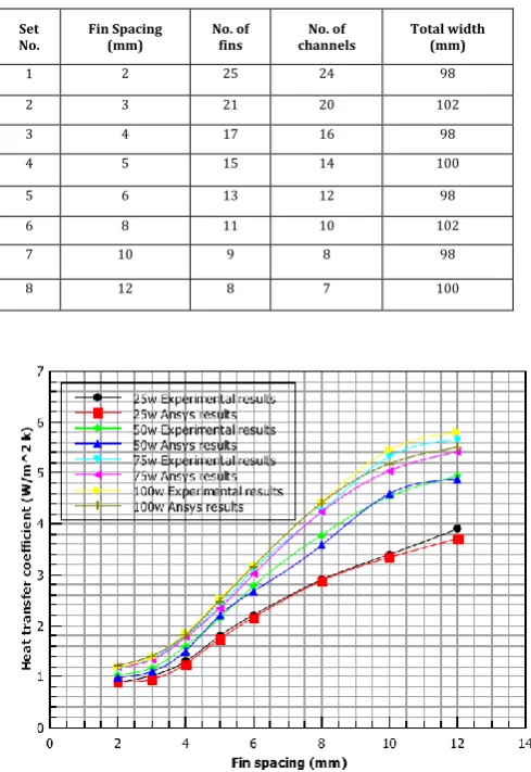
Many researchers carried out experimentation on HRFA in free environment and analysed the effect of geometrical parameters of fin on free convection heat transfer and fluid flow characteristics. In this study simulations are carried out by varying the fin spacing to height (S/H) ratio from 0.05 to 0.3 keeping the Length to height ratio constant i.e. L/H=5. The details of aluminum fin array assembly are tabulated in Table-2. Fins measuring 200mm in length, 100mm in width and 40mm in height were considered for analysis at different heat loads. The results obtained from FEA simulations were compared with the experimental results obtained by S. G. Taji et.al [1]. The results were plotted in Fig-3 and it is evident that both the FEA and experimental results are in good agreement with each other.
Table -2: Details of fin array assembly
Set No.
Fin Spacing (mm)
No. of fins
No. of channels
Total width (mm)
1 2 25 24 98
2 3 21 20 102
3 4 17 16 98
4 5 15 14 100
5 6 13 12 98
6 8 11 10 102
7 10 9 8 98
8 12 8 7 100
Fig -3: Comparison between FEA and experimental results for variation in fin spacing
2.2 Notched fin array
[image:2.595.35.288.187.341.2]
© 2016, IRJET | Impact Factor value: 4.45 | ISO 9001:2008 Certified Journal
| Page 743
Table -3: Fin characteristicsFin dimensions Values
Length of fin (mm) 127
Height of fin (mm) 38
Fin thickness (mm) 1
Fin spacing (mm) 9
No. of fins 7
Fin material copper
Base plate dimension (mm x mm x mm) 190 x 110 x 1
Base plate material copper
Table -4: Comparison between FEA and experimental results for notched and unotched fin array
Heat supplied
(W)
Heat transfer coefficient (W/m2k)
Without notch With 20% notch
Exp. [5] Ansys Error (%) Exp. [5] Ansys Error (%)
50 8.0595 7.92 1.73 9.3397 9.31 0.32
60 8.2307 8.22 0.13 9.6269 9.46 1.73
70 8.5519 8.45 1.19 10.01 10 0.09
[image:3.595.291.565.57.217.2]80 8.713 8.52 2.22 10.279 10.2 0.77
Fig -4: Comparison between FEA and experimental results for notched and unotched fin array
(a)
(b)
Fig -5: Contours of surface HTC at 80W (a) unotched fin array (b) notched fin array
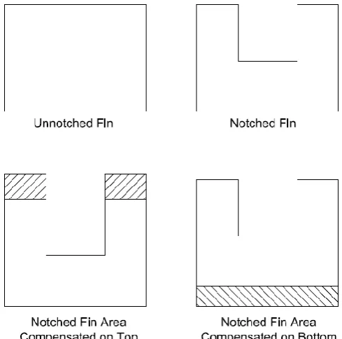
2.2.1 Area compensation of notch
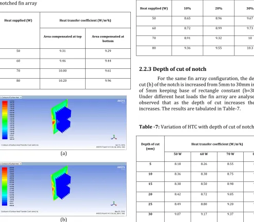
The analyses were carried out by compensating the area at top and bottom portion of the fin array for 20% cut of notch as shown in Fig-6. The simulations were carried for varying heat loads. The results obtained from FEA simulations are tabulate in Table-5. It is apparent that compensating area at top portion of fin is more efficient compared to area compensated at the bottom. Fig-7 shows the contours of surface HTC at 50W of heat load.
[image:3.595.31.287.296.593.2] [image:3.595.312.557.390.632.2]© 2016, IRJET | Impact Factor value: 4.45 | ISO 9001:2008 Certified Journal
| Page 744
Table -5: Comparison between FEA results obtained for areacompensated at top and area compensated bottom of notched fin array
Heat supplied (W) Heat transfer coefficient (W/m2k)
Area compensated at top Area compensated at bottom
50 9.31 9.29
60 9.46 9.44
70 10.00 9.61
80 10.20 9.96
(a)
(b)
Fig -7: Contours of surface HTC at 50w (a) Area compensated at top (b) Area compensated at bottom
2.2.2 Percentage cut of notch
For the same fin array configuration, the height of fin is changed to 45.6mm and analysed for 10%, 20% and 30% cut of notch under different heat loads. The area removed due to notch is not compensated by area compensation method. The FEA results are tabulated in the Table-6. It is observed that the HTC increases with increase in percentage cut of notch.
Table -6: Variation of HTC with percentage cut of notch
Heat supplied (W) 10% 20% 30%
50 8.65 8.96 9.67
60 8.72 8.99 9.73
70 8.91 9.32 10
80 9.36 9.55 10.3
2.2.3 Depth of cut of notch
For the same fin array configuration, the depth of cut (h) of the notch is increased from 5mm to 30mm in steps of 5mm keeping base of rectangle constant (b=38mm). Under different heat loads the fin array are analysed and observed that as the depth of cut increases the HTC increases. The results are tabulated in Table-7.
Table -7: Variation of HTC with depth of cut of notch
Depth of cut (mm)
Heat transfer coefficient (W/m2k)
50 W 60 W 70 W 80 W
5 8.18 8.26 8.55 8.57
10 8.36 8.38 8.75 9.04
15 8.38 8.50 8.98 9.12
20 8.42 8.72 9.05 9.26
25 8.49 8.80 9.20 9.62
30 9.07 9.17 9.37 9.91
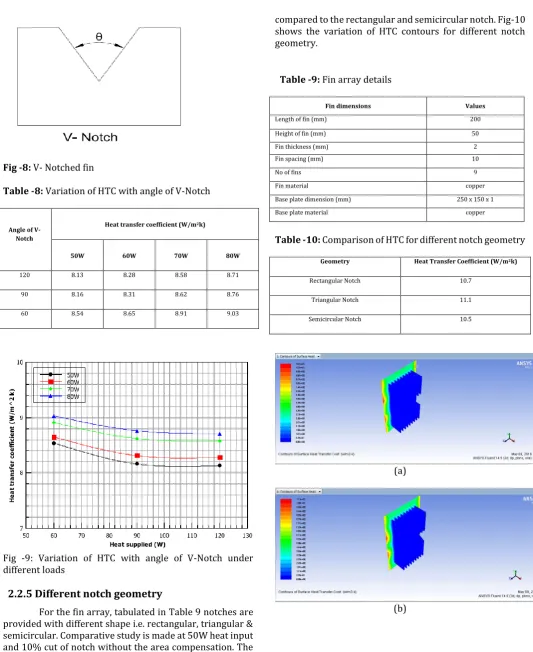
2.2.4 V- notch
© 2016, IRJET | Impact Factor value: 4.45 | ISO 9001:2008 Certified Journal
| Page 745
Fig -8: V- Notched finTable -8: Variation of HTC with angle of V-Notch
Angle of V- Notch
Heat transfer coefficient (W/m2k)
50W 60W 70W 80W
120 8.13 8.28 8.58 8.71
90 8.16 8.31 8.62 8.76
60 8.54 8.65 8.91 9.03
Fig -9: Variation of HTC with angle of V-Notch under different loads
2.2.5 Different notch geometry
For the fin array, tabulated in Table 9 notches are provided with different shape i.e. rectangular, triangular & semicircular. Comparative study is made at 50W heat input and 10% cut of notch without the area compensation. The results are tabulated in Table 10, from the results it can be concluded that the HTC is greater for triangular notch
compared to the rectangular and semicircular notch. Fig-10 shows the variation of HTC contours for different notch geometry.
Table -9: Fin array details
Fin dimensions Values
Length of fin (mm) 200
Height of fin (mm) 50
Fin thickness (mm) 2
Fin spacing (mm) 10
No of fins 9
Fin material copper
Base plate dimension (mm) 250 x 150 x 1
[image:5.595.37.293.293.637.2]Base plate material copper
Table -10: Comparison of HTC for different notch geometry
Geometry Heat Transfer Coefficient (W/m2k)
Rectangular Notch 10.7
Triangular Notch 11.1
Semicircular Notch 10.5
(a)
[image:5.595.293.571.332.706.2]© 2016, IRJET | Impact Factor value: 4.45 | ISO 9001:2008 Certified Journal
| Page 746
(c)Fig -10: Contours of surface HTC (a) Rectangular notch (b) Triangular notch (C) Semicircular notch
3. CONCLUSIONS
In this paper, the finite element analysis is carried out on horizontal rectangular fin array by varying the geometrical parameters such as fin spacing, percentage cut and depth of cut of notch. The conclusions were drawn from this analysis are listed below
For a given fin configuration, HTC increases with increase in fin spacing reaches optimum value & then decreases.
For smaller fin spacing the HTC reduces because of chocked flow.
The HTC for notched fin array is superior to the unnotched fin array.
The area compensation at the top portion of the fin increases the HTC compared with the area compensated at the bottom portion of the fin.
The HTC increases with increase in percentage cut of notch.
The HTC increases with increase in depth of cut of notch.
For the same percentage of cut, as the angle of V-Notch increases the HTC decreases.
For the same fin configuration, percentage of cut & heat load the HTC for triangular notch is higher than the rectangular & semicircular notched fin array.
REFERENCES
[1] S. G. Taji, G. V. Parishwad, N. K. Sane, “Experimental
investigation of heat transfer and flow pattern from heated horizontal rectangular fin array under natural convection,” Heat Mass Transfer (2014) 50:1005-1015.
[2] Salila Ranjan dixit, Dr D P Mishra, “Heat transfer analysis
through horizontal rectangular inverted notched fin array using natural convection by experimental method,” International Journal of Science & Engineering Research, Volume 4, Issue 7, July-2013, ISSN:2229-5518.
[3] G. P Lohar, S. Y. Bhosale, “Experimental investigation of
heat transfer for optimizing fin spacing in horizontal rectangular fin array under natural and forced convection & validation using CFD,” International
Journal For Technological Research In Engineering, Volume 2, Issue 2, October-2014, ISSN:2347-4718.
[4] S. D. Wankhede, S. G. Taji, V. M. Suryawanshi,
“Experimental investigation of heat transfer from inverted notch fin array(INFA) under natural anf forced convections,” IOSR-Journal of Mechanical and Civil Engineering (IOSR-JMCE), ISSN:2278-1684.
[5] Shivdas S. Kharche, Hemant S. Farkade, “Heat transfer
analysis through fin array by natural convection,” International Journal of Emerging Technology and Advanced Engineering, Volume 2, Issue 4, April 2012, ISSN:2250-2459.
[6] Mr. Vishal Hegana, Mr. P. R. Kulkarni, “Review of natural
convection heat transfer from different configuration of horizontal rectangular fin arrays,” Internation Journal of Innovation in Engineering, Research and Technology, ICITDCEME’15 Conference Proceedings, ISSN:2394-3696.
[7] S. R. Dixit, Dr. D. P. Mishra, Dr T C Panda, “Experimental
analysis of heat transfer and average heat transfer coefficent through fin array with or without notch using free convection,” International Journal of Advanced Research, Volume 1, Issue 2, May 2013, ISSN:2320-9186.
[8] S. S. Sane, N. K. Sane, G. V. Parishwad, “Computational
analysis of horizontal rectangular fin arrays dissipating heat by natural convection,” 5th European Thermal-Science Conference, The Netherlands, 2008.
[9] Allan Harry Richard. T. L, Agilan. H, “Experimental
analysis of heat transfer enhancement using fins in pin fin apparatus,” International Journal of Core Engineering & Management (IJCEM) Volume 2, Issue 1, April 2015, ISSN:2348-9510.
[10] Anurag Dahiya, Abhishek Nandan, “Review over natural
cnvection heat transfer coefficient of various fins,” International Journal of Engineering Research & Technology (IJERT) Volume 4, Issue 05, May-2015, ISSN:2278-0181.
[11] Mohsin A. Ali, S. M. Kherde, “Heat transfer analysis by
CFD simulation for different shapes of fins”, International Journal for Research in Applied Science & Engineering Technology, Volume 3, Issue II, February 2015, ISSN:2321-9653.
[12] Abdullah H. AlEssa, Ayman M. Maqableh, Shatha
Ammourah, “Enhancement of natural convection heat transfer from a fin by rectangular perforations with aspect ratio of two,” International Journal of Physical Sciences, Volume 4, October 2009, ISSN:1992-1950.