© 2015, IRJET.NET- All Rights Reserved
Page 977
A CLOSED LOOP ANALYSIS OF Z-SOURCE INVERTER FED INDUCTION
MOTOR DRIVE WITH VARIABLE LOAD TORQUE
Shobhana D. Langde
1, Dr. D.P. Kothari
21
M.tech Student, Electrical Engineering Department, W.C.E.M., Maharashtra, India
2
Director Research, Electrical Engineering Department, GPGI Group, Maharashtra, India
---***---Abstract -
This paper presents performancecharacteristics of Z-source inverter (ZSI) fed Induction Motor (IM) drives. ZSI has unique impedance network coupled between the power source and converter circuit to provide voltage buck and boost properties which cannot be achieved with conventional voltage source
and current source inverters. To facilitate
understanding of speed control for ZSI fed IM drives v/f control with simple boost PWM technique used. Simulation results of ZSI fed IM drives are compared with traditionally used VSI fed IM drives gives better performance for variable load torque, speed, rotor current characteristics.
Key Words: SPWM, Simple-boost control, Induction
Motor drives, Voltage source inverter, Z-source
inverter.
1.
INTRODUCTION
A ZSI is a type of power inverter, a circuit that converts direct current to alternating current. It functions as a buck-boost inverter without making use of DC-DC converter bridge. Generally there two types of traditional inverter: Voltage Source Inverter (VSI) and Current Source Inverter (CSI). In conventional Voltage-Source Inverter, the dc capacitor is the sole energy storage and filtering element to suppress voltage ripple and serve temporary storage. The AC voltage limited below and cannot exceed the dc-rail voltage the VSI is a buck (step-down) inverter. As upper and lower devices of each phase leg gated simultaneously either by any reason or by Electromagnetic Interference (EMI) noise causes a shoot-through problem which effect on reliability of inverter and dead time to block both upper and lower devices provided in VSI which cause waveform distortion because of this VSI has relatively low efficiency.
The VSI fed IM Drives suffers from some common problems like
Obtained output voltage is limited quite below the input voltage.
Voltage sag can interrupt the drive system and shut down critical loads as dc-capacitors in VSI
fed IM drives is small energy storage element which cannot hold dc voltage above level under such voltage sag.
Inrush and harmonic current can distort the line.
Miss-gating cause shoot-through problem and common mode voltage causes shaft current reason in failures of the motor and dead time cause low reliability and has unstable operation at low speeds.
A recently developed new inverter, Z-source inverter for motor drives overcome all above mentioned problems.
2.
EQUIVALENT
CIRCUIT
AND
OPERATING
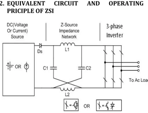
[image:1.595.310.567.381.576.2]PRICIPLE OF ZSI
Fig -2.1: General Structure of Z-Source Inverter
© 2015, IRJET.NET- All Rights Reserved
Page 978
be generated by different ways via anyone phase leg,combination of any two legs and all three legs.
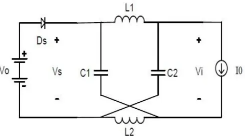
Fig -2.2: Equivalent circuit of ZSI in shoot-through zero switching state.
Fig -2.3: Equivalent circuit of ZSI in Traditional zero switching state.
To known the operating principle of the ZSI, figure 2.2 shows equivalent circuit of the Z-Source Inverter viewed from DC link. Figure 2.3 shows the inverter bridge is equivalent to a short circuit when inverter bridge in shoot-through zero state, whereas the inverter bridge becomes an equivalent current source as shown in figure 2.4 when in one of the six active states.
Fig -2.4: Equivalent circuit of ZSI in non-shoot through zero switching state.
For circuit analysis to get output voltage assuming that the inductors L1 and L2 and capacitors C1 and C2 have same
inductance (L) and capacitance (C) respectively. As summarized all equations. The output peak phase voltage from the traditional inverter can be expressed as
In ZSI one more additional control parameter is introduced, named as the Boost Factor (B), which modifies the AC output voltage equation of Z-Source Inverter as following
Where,
= Maximum sinusoidal inverter output voltage M = Modulation Index
= DC input voltage
The Boost factor is given as
Where, T0 is the shoot-through interval over one switching
cycle T.
3.
SIMPLE BOOST CONTROL METHODS
[image:2.595.40.282.133.258.2] [image:2.595.38.286.299.429.2] [image:2.595.39.285.567.704.2]© 2015, IRJET.NET- All Rights Reserved
Page 979
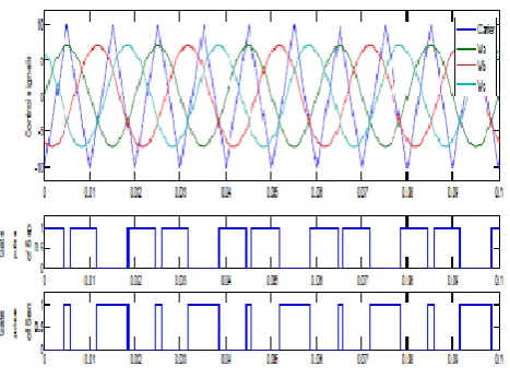
Fig -3.1: PWM Signal of Simple Boost Control. [image:3.595.312.555.252.389.2]In three-phase SPWM, a triangular voltage waveform (carrier waveform ) is compared with three sinusoidal control voltages (reference waveform), which are 120˚ out of phase with each other and the relative levels of the waveforms are used to control the switching of the devices in each phase leg of the inverter.
Fig -3.2: SinusoidalPWM technique
4.
CLOSED LOOP V/F CONTROLLED INDUCTION
MOTOR DRIVE
The volts per hertz (V/F) induction motor drives with inverters are widely used in a number of industrial applications leading not only to energy saving, but also to improvement in productivity and quality. This is the effective way of producing a variable speed drive is to supply the induction motor with variable magnitude and variable frequency AC supply and variable frequency is required because rotor speed depends on the speed of rotating magnetic field provided by stator which depends on supply frequency. A variable voltage is required because the motor impedance reduces at low frequencies
and consequently the current has to be limited by means of reducing the supply voltage is given by this method. The main advantage of V/F control is its simplicity. This paper presents V/F control for speed control of a three phase IM fed by a high performance ZSI. A simplified diagram of the V/F controlled induction motor is shown in Fig.4. When accuracy in speed response is a concern, closed-loop speed control can be implemented with the constant fv principle through the regulation of slip speed. A PI controller is employed to regulate the slip speed of the motor to keep the motor speed at its set value.
Fig -4: V/F based closed loop speed control scheme of an Induction Motor.
The closed loop control by slip regulation of the combined inverter induction motor improves the dynamic performance. The speed loop error generates the slip
command through a proportional integral (PI) controller and a limiter. The slip is added to the speed feedback signal to generate the slip frequency command
. Thus the frequency command generates the voltage command through a Volts/Hz generator.
5.
VSI FED IM DRIVE AND ZSI FED IM DRIVE
In this paper, for the comparison of VSI and ZSI, two models are prepared in MATLAB/SIMULINK. ZSI fed IM drive model is based on simple boost control technique. Whereas, the VSI fed IM drive model is based on sinusoidal pulse width modulation (SPWM). All the traditional pulse width modulation (PWM) schemes can be used to control the ZSI and their theoretical input–output relationships.
6.
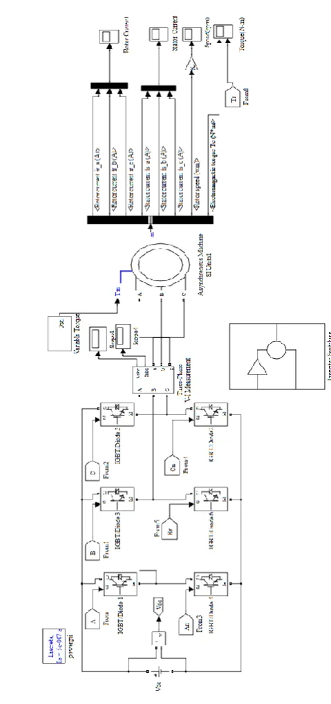
SIMULATION MODEL IN MATLAB
[image:3.595.44.278.410.583.2]© 2015, IRJET.NET- All Rights Reserved
Page 980
Fig -6.1:MATALB model of ZSI fed Induction Motor DriveFig -6.2: MATALB model of VSI fed Induction Motor Drive
7.
SIMULATION RESULT
0.3-© 2015, IRJET.NET- All Rights Reserved
Page 981
0.42 seconds, the variable torque of the range between [image:5.595.309.565.101.210.2]15-30N-m is applied in the step of 0.02 seconds.
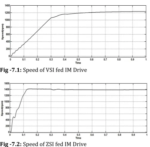
Fig -7.1: Speed of VSI fed IM Drive
Fig -7.2: Speed of ZSI fed IM Drive
[image:5.595.36.288.133.380.2]Figure 7.1 and 7.2, shows the speed of VSI fed IM drive and ZSI fed IM Drive respectively. From the results, it is clear that the ZSI gives better speed control than the VSI model. ZSI also provides less jerky motion at the starting of the motor as compared to VSI. When the variable torque is applied the change in the speed in VSI fed IM drive is greater and sudden as compared to ZSI fed IM drive. Figure 7.3 and 7.4 shows the rotor current for VSI fed and ZSI fed IM Drive resp. It shows that with ZSI, settling time for rotor current is decreased as compared to VSI. It is also clearly seen that VSI has more ripple component as compared to ZSI.
Fig -7.3: Rotor current of VSI fed IM Drive
Fig -7.4: Rotor current of ZSI fed IM Drive
[image:5.595.308.565.356.493.2]Figure 7.5 and 7.6, shows the electromagnetic torque of VSI fed IM drive and ZSI fed IM Drive with variable load torque respectively. From results, it is clear that the torque distortions are more in the VSI fed IM drive as compared to ZSI. It is also noted that with the ZSI fed IM drive attain the load torque with less time as compared to VSI
[image:5.595.309.557.530.654.2]Fig -7.5: Electromagnetic Torque of VSI fed IM Drive
Fig -7.6: Electromagnetic Torque of ZSI fed IM Drive
8.
CONCLUSIONS
[image:5.595.38.294.564.669.2]© 2015, IRJET.NET- All Rights Reserved
Page 982
results of ZSI Fed IM Drive under simple boost controlmethod showing better performance than ZSI Fed IM Drive.
REFERENCES
[1] F. Z. Peng, “Z-Source Inverter,” IEEE Transaction Industry Applications, vol. 39, pp. 504–510, March/April 2003.
[2] Fang Zheng Peng, Alan Joseph, JinWang, Miaosen Shen, Lihua Chen, Zhiguo Pan, Eduardo Ortiz-Rivera, Yi Huang, “Z-Source Inverter for Motor Drives” IEEE Transactions On Power Electronics, vol. 20, no. 4, pp. 857-863, July 2005.
[3] D. Kumar, Z. Husain, “ A Comparative Study of Z-Source Inverter Fed Three-Phase IM Drive with CSI and VSI fed IM,” International Journal of Power Electronics and Drive System (IJPEDS), vol.3, no.3, pp. 259-270, September 2013.
[4] F.Z. Peng, M. Shen, and Z. Qiang, “Maximum Boost Control of the Z-Source Inverter”, IEEE Transactions on Power Electronics, vol. 20, no. 4, pp. 833-838, July 2004.
[5] Omar Ellabban, Joeri Van Mierlo and Philippe Lataire,” Comparison between Different PWM Control Methods for Different Z-Source Inverter Topologies”, The 13th European Conference on Power Electronics and Applications, EPE '09. 8-10 Sept. 2009, Barcelona-Spain.
[6] Xinping Ding, Zhaoming Qian, Shuitao Yang, Bin Cui, Fangzheng Peng, “A New Adjustable-Speed Drives (ASD) System Based on High-Performance Z-Source Inverter” , IEEE Industry Applications Conference, 23-27 Sept. 2007, pp: 2327 – 2332.
[7] B. Singh, SP Singh, J Singh, M. Naim, “Performance evaluation of three phase induction motor drive fed from z-source inverter,” International Journal on Computer Science and Engineering (IJCSE), 2011. [8] B Husodo, S. M. Ayob, M. Anwari, Taufik, “Simulation
of Modified Simple Boost Control for Z‐Source Inverter,” International Journal of Automation and Power Engineering (IJAPE), Vol. 2, Issue 4, May 2013. [9] T.Meenakshi, K.Rajambal, “Identification of an
Effective Control Scheme for Z-Source Inverter”, Asian Power Electronics Journal, vol. 4, no. 1, April 2010.
[10]M. H. Rashid, Power Electronics, 2nd ed. Englewood Cliffs, NJ: Prentice-Hall, 1993.
BIOGRAPHIES
Shobhana D. Langde was born in India in 1991. She received his bachelor’s degree from R.T.M. Nagpur University on 2012. She is currently pursuing Master in Technology in PEPS from W.C.E.M., Nagpur from the same university.