© 2016, IRJET | Impact Factor value: 4.45 | ISO 9001:2008 Certified Journal | Page 1
Design of an IoTMulti device for smart homes
Anh-Tuan Nguyen
1, Tung Hoang
1, Anh-Tuan Do
1, Quang-Vinh Thai
21
Institute of Information Technology, Vietnam Academy of Science and Technology
2
Professor, Institute of Information Technology, Vietnam Academy of Science and Technology
---***---Abstract -
The Internet of Things (IoT) is a computingconcept that describes a future where every day physical objects will be connected to the Internet and be able to identify themselves to other devices. In the future, every device is more likely to be connected to the web directly while users can expect it to be responsive to their needs. In this project, we develop an IoTMulti device for controlling and sensing in smart homes using Wi-Fi enabled communication. The implementation of IoT based smart home-automated system to remotely control the home appliances uses Wi-Fi and Message Queuing Telemetry Transport (MQTT) for messaging protocol that designed for lightweight communications. A low-cost Wi-Fi module ESP8266 is used to build IoTMulti device. Users can remotely operate home appliances and monitor temperature, humidity in through Internet by using smartphones. Therefore, the concept of IoT is being used to make home smarter.
Key Words: Internet of Things, ESP8266, MQTT, Sensor,
Wi-Fi.
1.
INTRODUCTION
Internet of Things (IoT) is the extension of the current Internet in order to establish the communication, connection, and internetworking among various devices or physical objects called as "Things". IoT can be described as the connection of the various types of objects like smart phones, personal computers and tablets to the Internet, which brings about a very newfangled type of communication between things and people and also between things together. The key feature of IoT is the ability of networking devices to sense and collect data from the world around us, and then share that data across the Internet where it can be processed and utilized for various purposes. The research and development of home automation are becoming increasingly widespread in the recent years with the introduction of IoT. Home automation system represents and reports the status of the connected devices in an intuitive, user-friendly interface, which allows users to interact and control various devices by pressing one or some buttons on their devices. Some major communication technologies that are usually used by today’s home automation system are Bluetooth, WI-MAX and Wireless LAN (Wi-Fi) and Global System for Mobile Communication (GSM). Here we use Wi-Fi module which offers users a complete access control of the appliances through a remote interface. Automation refers to the use of control systems and information technology to control equipment, industrial
machinery and processes, reducing human intervention. The wide variety of potential IoT applications need an environment for software development that ties together the applications, the command, control and routing process and the security of the node and system. While the importance of software in MCU solutions has increased during the past few years, even more software, tools and enablement will be needed for MCUs supporting the IoT. A broad ecosystem with easily accessible support is the key to enable the development of embedded processing nodes and IoT applications.
2. SYSTEM OVERVIEW
In this section a detail design of IoTMulti device and the components used in it is presented.
2.1 System Architecture
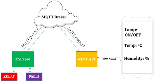
[image:1.595.313.562.496.626.2]In this work we will design a device, which is based on IoTMulti device using Wi-Fi module Esp8266 that is worked on AT command set and we are using MQTT protocols for communicating with smartphone.
Fig -1: System architecture diagram.
2.2 System Components
© 2016, IRJET | Impact Factor value: 4.45 | ISO 9001:2008 Certified Journal | Page 2
about as much Wi-Fi-ability as a Wi-Fi Shield offers (andthat’s just out of the box)! The ESP8266 module is an extremely cost effective board with a huge, and ever growing, community. This module has a powerful enough on-board processing and storage capability that allows it to be integrated with the sensors and other application specific devices through its GPIOs with minimal development up-front and minimal loading during runtime. Its high degree of on-chip integration allows for minimal external circuitry, including the front-end module, is designed to occupy minimal PCB area. The ESP8266 supports APSD for VoIP applications and Bluetooth co-existence interfaces, it contains a self-calibrated RF allowing it to work under all operating conditions, and requires no external RF parts.
Fig -2: ESP8266-01 module and pin out
The pin out of the ESP8266-01 is as follows:
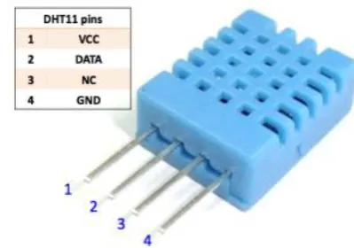
DHT11: DHT11 Temperature and Humidity Sensor features a calibrated digital signal output with the temperature and humidity sensor. Its technology ensures the high reliability and excellent long-term stability. A high-performance 8-bit microcontroller, which includes a resistive element and a sense of wet NTC temperature measuring devices, is connected. The key advantages of the sensor include excellent quality, anti-interference ability, fast response and high cost performance. Each DHT11 sensor features extremely accurate calibration of humidity calibration chamber. The calibration coefficients stored in the OTP program memory, internal sensors detect signals in
[image:2.595.333.533.206.346.2]the process. The single-wire serial interface system is integrated to become quick and easy. Another significant element of this product is that it is 4-pin single row pin package. Convenient connection and special packages can be provided according to the needs of users. Small size, low power and signal transmission distance up to 20 meters could help to develop a number of applications, even the most demanding applications.
Fig -3: DHT11-Temperature and Humidity Sensor
Regulator 3.3V (LM1117T): The LT1117 is a positive low dropout regulator designed to provide up to 800mA of output current. The device is available in an adjustable version and fixed output voltages of 2.85V, 3.3V and 5V. The 3.3V version is designed specifically to be used in Active Terminators for the SCSI bus. All internal circuitry is designed to operate down to 1V input to output differential. Dropout voltage is guaranteed at a maximum of 1.2V at 800mA, decreasing at lower load currents. On chip trimming adjusts the reference/output voltage to within ±1%. Current limit is also trimmed in order to minimize the stress on both the regulator and the power source circuitry under overload conditions.
[image:2.595.43.253.276.471.2]© 2016, IRJET | Impact Factor value: 4.45 | ISO 9001:2008 Certified Journal | Page 3
3. SYSTEM IMPLEMENTATION
3.1 System Components
[image:3.595.309.556.113.342.2]The IoTMulti hardware has 3 modules: Power supply module, ESP8266 module and RELAY module.
Fig -5: IoTMulti block diagram
[image:3.595.44.287.201.311.2]Power supply module: Largely determines the stability of a product. The input of this module is 220 V, and the output power supply is 5 V. As shown in Fig. 6, power supply module is designed in flyback topology to meet the requirements of 220 V AC input and 5 V DC output, since its output voltages are not limited by its input voltages, which can be as low as required to drive components or chips connected.
Fig -6: Schematic of power supply module
In schematic, B1 is a full wave rectifier, which rectify AC to rectifier DC. The rectifier DC is then filtered by a pi (π) filter consist of capacitors C1, C2 and inductance L1 to reduce electromagnetic interference noise. Features of high efficiency, high power density, and low cost are required in transformer. T1 is a transformer design for flyback topology.
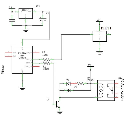
[image:3.595.308.557.376.540.2]ESP8266 module and RELAY module:
Fig -7: Schematic of IoTMulti device
Fig -8: IoTMulti device prototype
3.2 Software Design
MQTT protocol:
The Message Queue Telemetry
Transport (MQTT) was released by IBM and targeted
lightweight M2M communication. It runs over TCP and
supports for publishing and subscribing architecture.
In this paper, we use this MQTT protocol which
contains three QoS levels.
QoS 0 - At most once
QoS 1 - At least once
QoS 2 - Exactly once
[image:3.595.45.285.462.557.2]© 2016, IRJET | Impact Factor value: 4.45 | ISO 9001:2008 Certified Journal | Page 4
one side is client and other side is server. For instance, [image:4.595.307.535.104.716.2]temperature sensor that senses temperature data and publishes whatever they have to Hive-MQ broker which is one type of free online broker.
Fig -9: MQTT Publish/Subscribe architecture
On the client side, two essential devices are a laptop and a mobile phone, and they have subscribed temperature topic in order that whatever temperature data could be sent through broker to these two devices. In this way, the server can publish data while the client can receive that data. This is publish/subscribe architecture, and a very good example of MQTT protocol is Facebook Messenger.
Software programming: Different type of software and programing language are used for programing in ESP8266 Wi-Fi module. This paper has used Arduino IDE software for programing in ESP8266. Arduino IDE is most common very easy to learn and very simple to understand software available on the market. This is open software you can download the latest version on official website www.arduino.cc. If Arduino IDE is being installed then install ESP8266 Board. After that check blink example and dumped in ESP8266 device for test. A very simple example of home automation is light on or off and monitor temperature and humidity parameter using your android phone.
4. RESULTS
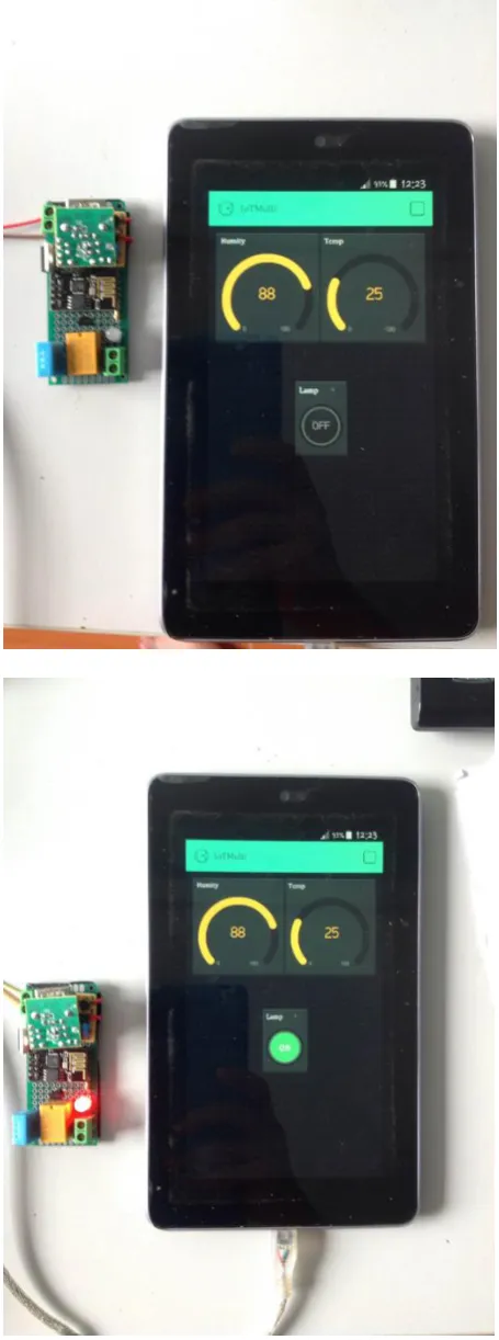
Using IoTMulti application we can communicate with
our appliances. Following are the screenshot taken
from mobile phone of the IoTMulti application. As
shown in fig -10 below, values of temperature and
humidity measurements are respectively: 88% and
25
oC. After click Lamp button on the application, the
LED on IoTMulTi device is light up.
[image:4.595.45.283.161.282.2]© 2016, IRJET | Impact Factor value: 4.45 | ISO 9001:2008 Certified Journal | Page 5
5. CONCLUSIONS
In this paper, we present a model of Wi-Fi Based Remotely Operated Smart Home Automated System using the Concept of Internet of Things. The IoTMulti device is connected with cloud and operated remotely through a mobile application. Some good features like notifications and basic home control system requirements are added to the device. With a number of advantages such as efficient, fast and labor saving, this proposed model has a wide variety of applications in home automation system.
REFERENCES
[1] Sye Loong Keojh, Sandeep s. Kumar, Hannes Tschofenig, Securing the Internet of Things: A Standardization Perspective, Internet of Things Journal IEEE (Volume: 1, Issue: 3), June 2014, pp. 268-275
[2] Jijun Xing, Study on Remote Wireless Smart Pot System Based on ZIGBEE+MQTT, International Journal of Future Generation Communication and Networking Vol. 9, No. 5 (2016), pp. 1-8
[3] Yu Ping Zhang, Tao Liu, Zhong Xiao Yang, Yi Mou, Yu Hua Wei, Dong Chen, Design of Remote Control Plug, Proceedings of 2015 IEEE International Conference on Applied Superconductivity and Electromagnetic Devices Shanghai, China, November 20-23, 2015
[4] Neil Kolban “Kolban’s Book on ESP8266”, 2015 [5] http://www.hivemq.com/blog/mqtt-essentials-part [6]
http://www.internetoflego.com/weather-station-dht11-mqtt-node-red-google-chart-oh-my/