© 2016, IRJET | Impact Factor value: 4.45 | ISO 9001:2008 Certified Journal | Page 1853
Design of Suspension Ball Joint Using FEA and Experimental Method
Jitendra Shinde
1, Sunil Kadam
21
P.G. Student, Department of Mechanical Engineering, Bharati Vidyapeeth’s College of Engg, Kolhapur, India
2Associate Professor, Head of Mechanical Department, Bharati Vidyapeeth’s College of Engg, Kolhapur, India
---***---Abstract -
This study describes the design and analysis of asuspension system ball joint using finite element analysis and experimental method .The axis of the ball joint element showed a complete fracture which occurred midway between the top and bottom section changes of the element. So there should be something else supports car when the ball-joint fails. This research has a modification of this ball joint for this purpose. Design of ball joint is modified and stress raisers are removed from the previous design of ball joint. Also validate that software results by experimental method. Design of the present ball joint has been improved and from obtained results we can say that the design of ball joint is modified and within safety limit.
Key Words- Ball joint, Modelling, Stress and Fatigue
analysis, Design modification, experimental method
1. INTRODUCTION
Ball joint is an important part of car suspension system. Ball joints act as the pivot point between two parts: the suspension and car’s tires. Ball joints help support car’s weight.. The ball joint is one moveable part of a control arm assembly. It is steel bearing stud and socket enclosed in a steel casing. The socket enclosed in steel casing is connected to the control arm. The bearing stud is tapered and threaded so that it fits into a tapered hole in the steering knuckle and the latter connects the tire. This connection needs to be able to rotate horizontally for steering and vertically for shock absorption, hence the use of ball joints that can move in all directions. This projected study is an overall revive of existing ball joint failure and to minimize this failures by improving some failure parameters. So that it will helps to maximize life of ball joint and resulting minimizing road accidents. [1]
1.1
Problem Definition
The failure of ball joint is due to the fracture initiated at the contact point between the ball joint element and its cage where stress concentration creates. Further the reduction of the cross section on the ball joint element leads to stress concentration which further reduces the life of the element. In order to reduce the contact stresses on the ball element
change of the geometric design of the element is necessary. To minimize the failure of suspension ball joint by improving geometrical design of suspension ball joint to achieve maximum performance. [3]
1.2
Methodology
To solve the problem mention above we have first import the Para solid model to the ANSYS which is analysis software by using which we have to solve the problem. In the next step we have to do the meshing on ball joint. Next step we have to apply loads i.e. force and torque which are mentioned in the load case then after we have to apply the boundary conditions by seeing the actual model i.e. where it is fixed. Then we have to solve the problem by using software. After completion of the solution by using software we have to do the physical testing of suspension ball joint.
1.3 Design tool
Various tools were used in the development of our design. The CATIA software is used for tasks such as the three dimensional solid modeling of suspension ball joint. The use of solid modeling techniques allows us the computerization of many difficult engineering calculations that are carried out as a part of the design process. Simulation, planning, and verification of processes of the components of the suspension are some of the tasks that will be performed in CATIA. Also ANSYS software will be used to perform an engineering analysis of the stresses acting on component to reveal the state of stress and failure on the device.
2. MODELING AND ANALYSIS OF BALL JOINT
The measurements of main parts of ball joint have been made in order to create a three dimensional geometry by CATIA software. Then, the model (geometry) has been imported to ANSYS workbench software.
© 2016, IRJET | Impact Factor value: 4.45 | ISO 9001:2008 Certified Journal | Page 1854
Table No.1: Dimensions of Suspension Ball JointFig -1: 3D-Model
2.1
Material
According to Spectro test results the ball joint was manufactured using an EN 18D steel alloy.
EN 18D Steel Alloy properties:
• Yield stress=565 MPa
• Ultimate tensile strength=887 MPa
• Density =7.85g/cm3
• Poisson’s ratio = 0.29
2.2 Meshing Generation
Meshing of a given model will be done depending on geometry of the model, it is better to have more degrees of freedom hence more number of elements so that results obtained will be closure to analytical results. In two bay panel analyses, crack region is meshed with more number of elements when compared with other parts of fuselage, for obtaining a converged solution which in turn a better solution. [1] The fundamental premise of FEM is that as number of elements (mesh density) is increased, the solution
gets closer and closure, however solution time and compute resources required also increases dramatically as we increases the number of elements to the true solution
Chart -1: Name of the chart
IRJET sample template format ,Define abbreviations and acronyms the first time they are used in the text, even after they have been defined in the abstract. Abbreviations such as IEEE, SI, MKS, CGS, sc, dc, and rms do not have to be defined. Do not use abbreviations in the title or heads unless they are unavoidable.
[image:2.595.307.560.146.384.2]
Fig - 2: Meshing of ball joint
2.3 Loading and Boundary Condition
Each tire of this vehicle has a share of the car’s weight, gross weight and weights of persons riding the car. The centroid of this car under its full static load is located at the a point of intersection of its diagonal axes, consequently, each tire has a share of quarter of that full static load, If the car has a gross weight of 2300 kg and the weight of its passengers and luggage is 620 kg as well as each passenger is assumed to weight of 100 kg, the total static load will be 2300 kg .So each tire will have a share of 575 kg. when the a car has an impact within the motion, ball joint subjects to longitudinal load equals nearly to double of its tire share static load as well as horizontal load equals to that longitudinal one but it directs a horizontally along the length of car.
A load of (2X575X 9.81)N is applied downward to stud at the thread place in its longitudinal direction while other load of(2X575X9.81)N is applied horizontally at a place where it is in contact with knuckle, also a general joint is added to this region to keep only linear motion. A fixed boundary condition is applied to the socket at a place where it’s bonded to the lower control arm.
The fatigue stress and its safety factor have been created in these two forms of numerical analysis, the load on ball-joint is fluctuating between its maximum (where the ball-joint faces an impact) and the static load which only includes the weights of car, freight and persons.
Diameter Dimension in mm
D1 30
D2 20
© 2016, IRJET | Impact Factor value: 4.45 | ISO 9001:2008 Certified Journal | Page 1855
Calculations for weight distribution on each wheel:Kerb Weight: 1680 Kgs Seating Capacity: 7
Gross Weight = Kerb Weight + Passenger weight + Luggage weight
WG = 2300 Kgs From standard
The ratio of weight distribution is F/R: 49/51 Weight acting on each front wheel
W = (0.50X WG)/2 = (0.50X 2300)/2 W = 575 Kg
So, the reaction force, P = WXg
= 575X9.81 P = 5640.75 N
P = 5700 N Appx.
Assumed condition is of bump, in which the extremity of load is present.
The load considerations are Double Gravity (2g acceleration)
[image:3.595.308.555.154.358.2]P = 11400 N (taken for Analysis)
Fig- 3:Loading and Boundary Condition
3.
RESULTS FOR ORIGINAL GEOMETRY
[image:3.595.308.560.393.607.2]From the above loading and boundary condition following results are obtained.
[image:3.595.36.286.481.715.2]Fig.4- : Equivalent Von-Mises stress
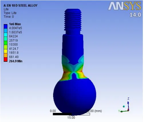
Fig - 5 : Fatigue life
© 2016, IRJET | Impact Factor value: 4.45 | ISO 9001:2008 Certified Journal | Page 1856
4. RESULTS FOR MODIFIED BALL JOINT
[image:4.595.307.565.142.480.2]After design modification improved results for ball joint shown below.
Fig- 6 : Equivalent Von-Mises stress
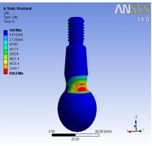
Fig - 7 : Fatigue life
Result of stress and fatigue analysis of modified ball joint shows that stress value has been brought to the safety limit. Hence design of ball joint is modified and stress raisers are removed from the previous design of ball joint.
[image:4.595.36.286.153.389.2]
4. COMPARISON OF ANALYSIS RESULTS
Table No.1: Comparison of Results
SR.
NO. COMPONENTS
BEFORE MODIFICAT
ION
AFTER MODIFICA
TION
1 Total Deformation 2.1 MM 0.2 MM
2 Equivalent Stress
Plot 959.49 MPa 589.37 MPa
3 Major Principal
Stress Plot 916.64 MPa 493.75 MPa
4 Equivalent Elastic
Strain Plot 0.0048 0.0111
5 Max Shear Stress 524.38 MPa 339.65 MPa
6 Factor of Safety 0.9289 1.505
7 Fatigue life 264 (min) cycle/s
941 (min) cycle/s
5. EXPERIMENTAL RESULTS
5.1 Spectro Test
After doing spectro test following are chemical composition are obtained and material of the ball joint was found.
Table No 3. : Chemical Composition
Materi
al
C Mn S P Cr NiEN-18D
steel
alloy
[image:4.595.36.287.420.661.2] [image:4.595.300.568.613.713.2]© 2016, IRJET | Impact Factor value: 4.45 | ISO 9001:2008 Certified Journal | Page 1857
5.2 Tensile test on Universal testing machine
Objective of tensile test for determine the stress-strain behavior of a material sample and to analyze the results of the tensile test t find the mechanical properties.
Fig.4- : Test Specimen
Fig.4- : Tensile Test Set-Up on Universal Testing Machine After completing tensile test following result are obtained for EN 18D Steel Alloy.
EN 18D Steel Alloy mechanical properties:
• Yield stress=565 MPa
• Ultimate tensile strength=887 MPa
• Density =7.85g/cm3
• Poisson’s ratio = 0.29
• Elongation = 15.33 %
5.2 Shear test on Universal testing machine
During shear test we have first place the test attachment on lower table of universal testing machine and ball joint inserted in shear test attachment, then apply load and got the shear strength of ball joint. Figure shows the test set-up on universal testing machine.
Fig.4- : Shear Test Set-Up on Universal Testing Machine
© 2016, IRJET | Impact Factor value: 4.45 | ISO 9001:2008 Certified Journal | Page 1858
3. CONCLUSIONS
The results for stress and fatigue analysis of ball joint with boundary condition for the previous ball joint tests shows that stress limit was crossed and the stress value is much higher than the ultimate tensile strength of the material, Also because of this there is no safe fatigue life to the ball joint .To modify the design of ball joint to make it safe, reliable and durable. We worked on the stress raiser in the previous design of ball joint and required design modification are done and results of stress and fatigue analysis of modified ball joint shows that stress value has been brought to the safety limit, the component is now have considerably good fatigue life. Hence design of ball joint is modified and stress raisers are removed from the previous design of ball joint. Design of the present ball joint has been improved and from obtained results we can say that the design of ball joint is modified and within safety limit. Also experimental validation of result through finite element analysis was done.
REFERENCES
[1] Jitendra Shinde,Sunil Kadam, amol patil and samuvel
pandit ,“Design Modification And Analysis Of Suspension Ball Joint Using Finite Element Analysis” journal of innovative reaserch in science, engineering and technology, vol. 5, july 2016
[2] Chen A., “Investigating the behavior of ball joint sealing
boots using a 3D Finite Element Model”, 2nd Worldwide
Automotive Conference, 2010
[3] E.A. Ossa, C.C. Palacio and M.A. Paniagua, “Failure
analysis of a car suspension system ball joint”Materials Engineering Research Group, Colombia, 2011
[4] Fischer, I. S., “Numerical analysis of displacement in
spatial mechanisms with ball joints”, Mechanism and Machine Theory,35 (2000) p. 1623-1640.
[5] Ryu YI, Kang DO, Heo SJ, Yim HJ, Jeon JI., “Development
of analytical process to reduce side load in strut-type suspension”. J MechSci Technol2010; 24:351–6.
[6] Suresh, S., “Fatigue of Materials”, 2nd ed., Cambridge
University Press, Cambridge, 1998.
[7] David Gorsich , “Vehicle Systems Engineering and
Technology”, Symposium, 2009.
[8] S. A. Kesulai , “European Journal of Scientific Research”, ,
Fatigue Life Prediction ISSN 1450-216X Vol.30 No.3 (2009).
BIOGRAPHIES
Mr. J.G.SHINDE PG Student
ME(CAD/CAM/CAE)