International Journal of Emerging Technology and Advanced Engineering
Website: www.ijetae.com (ISSN 2250-2459, Volume 2, Issue 11, November 2012)86
Control of Active and Reactive Power Flow in Multiple Lines
through Interline Power Flow Controller (IPFC)
Indra Prakash Mishra
1, Sanjiv Kumar
21
Research Scholar, 2Assistant Professor, Department of EE, Harcourt Butler Technological Institute, Kanpur
Abstract — In this paper a circuit model for IPFC is developed using series coupling transformers and comparison of active and reactive power of Transmission Lines with and without IPFC is presented using the proposed circuit model. Comparison is also done with individual Static Synchronous Series Compensators (SSSCs), one on each line of a two line system and the results are compared with the previous one. MATLAB with Simulink and SIM POWER SYSTEMS tools are used for simulation of Transmission lines and IPFC in open loop and closed loop configurations. A common DC link within the IPFC is able to facilitate real power transfer among the lines of the transmission system. Also each inverter can provide reactive power compensation independently.
Index Terms-- Interline Power Flow Controller (IPFC), FACTS devices, Reactive Power Compensation, Simulation of IPFC, Transmission line sag mitigation.
I. INTRODUCTION
The involvement of a new family of FACTS devices which is based on Voltage Source Converters (VSC) added the features like flexible power flow control, transient stability and power system oscillation damping enhancement. Static Synchronous (shunt) Compensator (STATCOM), the Static Synchronous Series Compensator (SSSC) the Unified Power Flow Controller (UPFC) and the Interline Power Flow Controller (IPFC) are the members of family of compensators and power flow controllers based on VSC.
The UPFC provide independent control both for the real and reactive power flow of individual transmission lines thereby providing the cost effective utilization. While the Interline Power Flow Controller (IPFC) concept provides compensation in a number of transmission lines. [3], [4], [8], [14]. The interline power flow controller (IPFC) is one of the latest FACTS controller used to control power flows of multiple transmission lines. Interline Power Flow Controller (IPFC) is an extension of static synchronous series compensator (SSSC). Any converters within the IPFC can transfer real power to any other and hence real power transfer among the lines may be carried out, together with independently controllable reactive series compensation of each individual line.
IPFC is developed with the objective of balancing real and reactive power flow among multi-lines and to transfer power from overloaded to under loaded lines. Second objective of IPFC is to compensate against reactive voltage drops and the corresponding reactive line power, thereby increasing the effectiveness of the compensating system against dynamic disturbances. An attempt is made in the present work to develop circuit model for four-bus system with IPFC and two series coupling transformers.
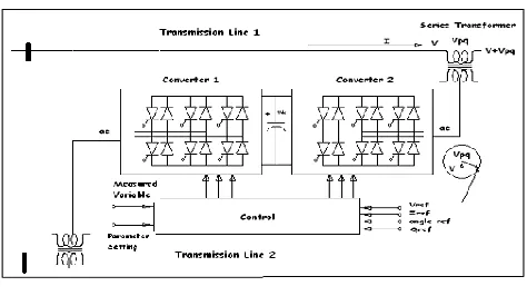
[image:1.612.325.562.344.477.2]A. Basic Interline Power Flow Controller
Fig 1: Basic Interline Power Flow Controller
The IPFC consists of two voltage sourced converters, connected back-to-back and are operated from a common dc link provided by a storage capacitor as shown in the fig.1
The arrangement shown in the fig.1 functions as an ideal ac-to-ac power converter in which the real power can freely flow in either direction between the ac terminals of the two converters, and each converter can independently generate (or absorb) reactive power at its own ac output terminal.
B. Generalized Interline Power Flow Controller
International Journal of Emerging Technology and Advanced Engineering
Website: www.ijetae.com (ISSN 2250-2459, Volume 2, Issue 11, November 2012)87
[image:2.612.326.563.215.450.2]With this scheme the net power difference at the ac terminal is supplied or absorbed by the shunt inverter, and ultimately exchanged with the ac system at the shunt bus. This arrangement can be economically attractive, because the shunt inverter has to be rated only for the maximum real power difference anticipated for the whole system. It can also facilitate relatively inexpensive shunt reactive compensation, if this is needed at the particular substation bus.
Fig 2: A Generalized Interline Power Flow Controller for Power Transmission Management
II. SIMULATION OF IPFC
A single phase system is considered for the purpose of simulation. Two lines are modeled, one as primary line and another as secondary line. The load of lines is selected in such a way to model one line as overloaded as compared to the primary. The primary and secondary lines are connected with identical voltage sources of 110kV. Primary voltage is at phase angle 150 and secondary voltage is at phase angle 300
A. Simulation of Two Transmission Lines without IPFC
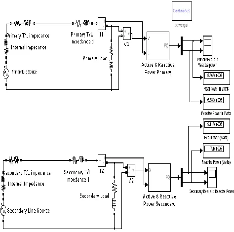
The simulation of two Transmission Lines without IPFC is done and active and reactive powers of primary and secondary loads are observed.MATLAB Simulation model of Primary and Secondary lines without IPFC is presented in Fig 3
Fig 3: MATLAB Simulation Model of Primary and Secondary Lines without IPFC
B. Simulation of Two Transmission Lines with Two individual SSSCs s
[image:2.612.50.287.246.453.2]International Journal of Emerging Technology and Advanced Engineering
Website: www.ijetae.com (ISSN 2250-2459, Volume 2, Issue 11, November 2012) [image:3.612.325.559.122.326.2]88
Fig 4: MATLAB Simulation Model of Primary and Secondary Lines with Individual SSSCs
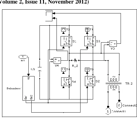
1) SSSC Subsystem
[image:3.612.51.292.133.355.2]Figure 5 and 6 present the SSSC subsystem for the primary line and secondary line. High speed switches are taken for the fabrication of converter. A capacitor is connected to act as DC link
.
Fig 5: SSSC Subsystem for Primary Line with Individual SSSC
Fig 6: SSSC Subsystem for Secondary Line with Individual SSSC
2) Pulse generation Module
The pulse generation module has been developed for switching of converters used throughout in this work. Sinusoidal signal is compared with the reference to produce rectangular pulses whose width is controllable through the reference. The MATLAB circuit for this module is shown below in Fig 7
Fig 7: Matlab Circuit model for Pulse Generation Module
C. IPFC in Open Loop
[image:3.612.325.558.433.644.2] [image:3.612.55.283.460.688.2]International Journal of Emerging Technology and Advanced Engineering
Website: www.ijetae.com (ISSN 2250-2459, Volume 2, Issue 11, November 2012)89
[image:4.612.321.564.136.339.2]In the present paper series coupling transformers are used at primary line side as well as at secondary line side. The MATLAB Simulink circuit model of the two-lines with IPFC connected in open loop is shown in figure 8.
Fig 8: Matlab Circuit Model of Open Loop IPFC System
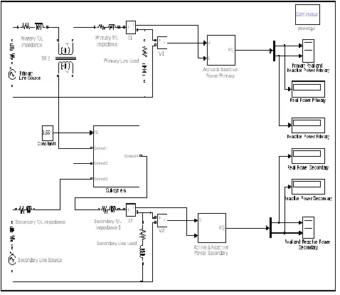
D. IPFC in Closed Loop
[image:4.612.50.289.189.396.2]The MATLAB Simulink circuit model of the IPFC connected in closed loop is shown in figure 9. Scopes are connected to the primary load and secondary load. Real and reactive powers in the loads are measured. Voltages across primary load and secondary load are sensed and compared. The output is given to a PI controller; the error produced will drive the PI controller, which produces the signal to be sent to input 1 of IPFC subsystem and controls the duty cycle of converters. Instead of comparing the load voltages of two lines the voltage of the secondary may also be compared with a fixed reference value suiting to our requirement. IPFC is connected at the mid point of transmission line. The primary source voltage is 110kV
150 and the secondary source voltage is 110kV
300. Linear transformers are connected at the primary line and at the secondary line in series with the respective lines.Fig 9: Matlab Circuit Model of Closed Loop IPFC System
1) IPFC Subsystem
The IPFC subsystem consisting of two back to back connected Voltage source converters system used in the IPFC model is shown in Fig. 10. Capacitor is used to create common DC link for both the converters.
[image:4.612.324.563.431.643.2]International Journal of Emerging Technology and Advanced Engineering
Website: www.ijetae.com (ISSN 2250-2459, Volume 2, Issue 11, November 2012)90
III. DATA ANALYSIS AND RESULTS
A. Simulation Results of Two Transmission Lines without IPFC
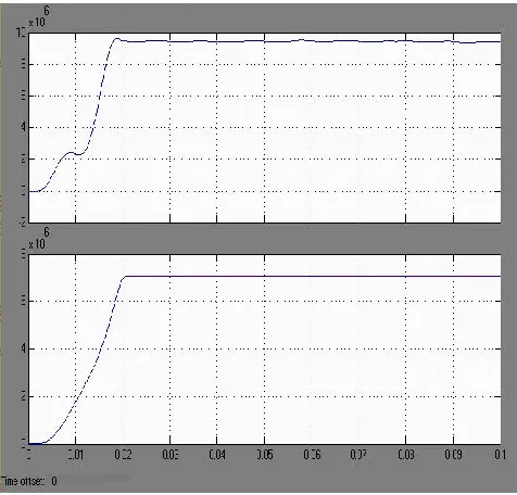
[image:5.612.323.565.192.309.2]At the beginning the simulation of model was done without IPFC. Simulation was done with equal voltages [110kV] on the input sides and different phase angles [Primary source voltage with phase angle 15o and secondary source voltage with 30o. Due to the difference in phase angle, there is an increase in the real power of the secondary load when compared to the primary load. The snap shots of scope showing the real and reactive power of secondary circuit are shown in figure 11.
Fig 11: Active and Reactive Power in Secondary Load without IPFC
The real powers in primary and secondary loads are shown in Table 1
TABLE 1
REAL AND REACTIVE POWERS OF PRIMARY AND SECONDARY
CIRCUITS WITHOUT IPFC
Lines without
IPFC
Primary Load Secondary Load Active
Power (MW)
Reactive Power (MVAR)
Active Power (MW)
Reactive Power (MVAR)
8.767
6.589
9.417
7.1
B. Simulation Results of Two Transmission Lines with individual SSSCs
TABLE 2
REAL AND REACTIVE POWERS OF PRIMARY AND SECONDARY
CIRCUITS WITH INDIVIDUAL SSSCS
Constant
referred to
Duty Cycle
Primary Load
Secondary
Load
Value % Active
Power (MW)
Reactive Power (MVAR)
Active Power (MW)
Reactive Power (MVAR)
0.8
66.67
8.78
1
6.578
9.467
7.092
Real and Reactive powers of primary and secondary circuits with individual SSSCs are observed. The variations in real and reactive powers of primary and secondary loads with respect to the duty cycle constant are recorded and presented in Table 2 and the corresponding snapshots of scopes are presented in Fig 12 and Fig 13.
[image:5.612.49.287.285.513.2] [image:5.612.324.565.386.618.2]International Journal of Emerging Technology and Advanced Engineering
Website: www.ijetae.com (ISSN 2250-2459, Volume 2, Issue 11, November 2012) [image:6.612.47.289.132.329.2]91
Fig 13: Active and Reactive Power in Secondary Load with Individual SSSC
C. Simulation Results of Two Transmission Lines with IPFC
1) Simulation in Open Loop Mode
The simulation was done with IPFC in open loop. Variation in Real and Reactive powers of primary and secondary circuits with respect to duty cycle of converter, are observed and tabulated in Table 3. Snap shots are shown in figure 14 and 15.
TABLE 3
VARIATION IN REAL AND REACTIVE POWERS OF PRIMARY AND
SECONDARY CIRCUITS, WITH RESPECT TO DUTY CYCLE OF
CONVERTER
Constant
referred to
Duty Cycle
Primary Load
Secondary
Load
Value % Active
Power (MW)
Reactive Power (MVAR)
Active Power (MW)
Reactive Power (MVAR)
0.8
66.6
7
[image:6.612.323.564.132.319.2]8.813
6.601
9.492
7.110
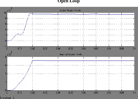
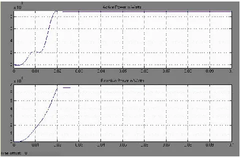
Fig 14: Active and Reactive Power in Primary Load with IPFC in Open Loop
Fig 15: Active and Reactive Power in Secondary Load with IPFC in Open Loop
2) Simulation in Closed Loop mode
[image:6.612.324.565.339.513.2] [image:6.612.46.291.508.623.2]International Journal of Emerging Technology and Advanced Engineering
Website: www.ijetae.com (ISSN 2250-2459, Volume 2, Issue 11, November 2012) [image:7.612.48.289.134.292.2]92
Fig 16: Active and Reactive Power of Primary Load with IPFC in Closed Loop
Fig 17: Active and Reactive Power of Secondary Load with IPFC in Closed Loop
The comparison of active and reactive powers with and without IPFC and with individual SSSC is presented in Table 4. The SSSC is capable of increasing the reactive power of secondary load from 7.088 MVAR in without IPFC system, to 7.092, with equal voltages (110 kV) at the source bus of both the lines, with phase angle of 150 for primary and 300 for secondary line. Further the IPFC increases the reactive power of secondary from 7.092 to 7.110 MVAR. In other words the proposed model improves the reactive power of the secondary line from 7.088 to 7.110 MVAR. The active power of the secondary is also increased from to 9.492 MW as compared to the value that of without IPFC. The consolidated simulation results are finally presented in Table 6.4.
TABLE 4
ACTIVE AND REACTIVE POWERS WITHOUT IPFC, WITH INDIVIDUAL
SSSC AND WITH IPFC
Condition
Primary Load
Secondary
Load
Active
Power
(MW)
Reactiv
e
Power
(MVA
R)
Activ
e
Powe
r
(MW
)
Reactiv
e
Power
(MVA
R)
Lines
without
IPFC
8.780
6.570
9.464
7.088
Lines with
Individual
SSSC
8.781
6.578
9.467
7.092
Lines with
IPFC
8.813
6.601
9.492
7.110
IV. CONCLUSIONS
IPFC is capable of balancing the power through the lines. The power quality is improved since IPFC permits additional power. The circuit models for IPFC system are simulated using MATLAB. These models are used for simulating a two line-four bus system. Improved model with transformer on both lines and back to back converters is presented which improves the reactive power of the secondary line from 7.088 to 7.110 MVAR. The active power of the secondary is also increased from to 9.492 MW as compared to the value that of without IPFC. In other words the proposed model of IPFC increases the real power transfer and improves the voltage profile.
REFERENCES
[1] Manuel Reta-Herna´ndez,: Chapter#13-Transmission Line Parameters©2006 Universidad Auto´noma de Zacatecas by Taylor & Francis Group, LLC.
[2] Yongan Deng, MASc student at Concordia University Reactive Power Compensation of Transmission Lines
[3] Overview of Flexible AC Transmission Systems, FACTS, issued by International Council on Large Electric Systems “CIGRE”,SC B4, HVDC and Power Electronics (CIGRE's Bilingual Bimonthly Journal for Power System Professionals)
[image:7.612.323.566.165.399.2] [image:7.612.49.290.319.481.2]International Journal of Emerging Technology and Advanced Engineering
Website: www.ijetae.com (ISSN 2250-2459, Volume 2, Issue 11, November 2012)93
[5] N.G. Hingorani, L. Gyugyi, Understanding FACTS, Concepts andTechnology of Flexible AC Transmission systems, IEEE Press 2000(Book)
[6] Proposed terms and definitions for flexible AC transmission system(FACTS), IEEE Transactions on Power Delivery, Volume 12, Issue 4, October 1997, pp. 1848–1853. doi: 10.1109/61.634216 [7] Juan Dixon (SM) ,Luis Morán (F) ,José Rodríguez (SM) , Ricardo
Domke Pontificia Reactive Power Compensation Technologies, State of- the-Art Review ,Universidad Católica de Chile Universidad de Concepción Universidad Federico Sta. María, Santiago - CHILE Concepción - CHILE Valparaíso – CHILE [8] D. Murali, Dr. M. Rajaram, Active and Reactive Power Flow
Control using FACTS Devices International Journal of Computer Applications (0975 – 8887) Volume 9– No.8, November 2010 45 [9] Hirofumi Akagi, Trends in active power line conditioners, posted at
e Scholarship @ OUDIR: Okayama University Digital Information [10] H. Frank and S. Ivner, “Thyristor-Controlled Shunt Compensation in
Power Networks,” ASEA Journal, vol. 54, pp. 121-127, 1981. [11] Douglas J. Gotham G. T. Heydt, Power Flow Control And Power
Flow Studies for FACTS Devices. IEEE Transactions on Power Systems, Vol. 13, No. 1, February 1998.
[12] Narain G. Hingorani, Laszlo Gyugyi Understanding FACTS: Concepts and Technology of Flexible AC Transmission Systems, Wiley-IEEE Press, December 1999. ISBN 978-0-7803-3455-7 (book)
[13] Bhanu CHENNAPRAGADA Venkata Krishna, KOTAMARTI. S. B. Sankar, PINDIPROLU. V. Haranath, GVPcollege of Engineering, Visakhapatnam-INDIA, POWER SYSTEM OPERATION AND CONTROL USING FACT DEVICES,17th International Conference on Electricity Distribution Barcelona, 12-15 May 2003
[14] G. Irusapparajan and S. Rama Reddy, Bharath University, Chennai, India, Jerusalem Engineering College, Chennai, India Experimental Results of Interline Power Flow Controller Systems, Research Journal of Applied Sciences, Engineering and Technology 3(7): 612-616, 2011, ISSN: 2040-7457 © Maxwell Scientific Organization, 2011
[15] Lazzlo Gyugyi, fellow, IEE, Kalyan K. Sen, member, IEEE, Colin D. Schauder, Member IEEE, The Interline Power Flow Controller Concept: A new approach to power flow management in Transmission Systems, IEEE Transaction on Power Delivery, Vol14, No.3, July 1999.