Optimal Location and Parameter Settings of UPFC
Using ACO for Enhancing Power System Security
under Single Contingencies
MD. Yaseen*, T. Anil Kumar
Department of EEE, Anurag Group of Institutions, India
Copyright©2019 by authors, all rights reserved. Authors agree that this article remains permanently open access under the terms of the Creative Commons Attribution License 4.0 International License
Abstract
Optimal setting and location of Flexible AC Transmission Systems (FACTS) devices are widely used in enhancing power system security. The most effective FACTS device is Unified Power Flow Controller (UPFC) which has both series and shunt compensation. The effectiveness of FACTS device over the mitigation of security issues depends on its location and its parameter settings. Hence, this paper presents Ant Colony Optimization (ACO) methodology to optimally locate UPFC to enhance power system security under single contingencies (N-1 Contingency). The simulation is carried out on IEEE 6 bus and IEEE 14 bus test systems considering line over loads and bus voltage violations for ensuring system security. This approach is twofold. Initially, an N-1 contingency test is performed based on severity ranking is done then UPFC is placed optimally using ACO algorithm to mitigate the severity. Further to validate the proposed approach the results are compared with the conventional Non Linear Programming – Interior Point (NLP-IP) technique.Keywords
Contingency Analysis, Power Flow, Unified Power Flow Controller (UPFC), Ant Colony Optimization (ACO), Non Linear Programming – Interior Point (NLP-IP)1. Introduction
In the present day power scenario with the ever increasing demand, the power utilities are looking for ways to maximize the utilization of their existing transmission system. This factor affects the system security to a great extent [1]-[2]. Further, it is uneconomical to meet these specifications using traditional approaches. Hence power system engineers are continuously striving to improve system security constraints such as thermal limits of
transmission lines and bus voltage limits under N-1 contingencies using modern technologies [3].
One solution to the above problem is to use Flexible AC Transmission System (FACTS) devices. These devices not only improve system security but also find many applications in power system such as improvement of system stability, damping oscillations and minimization of transmission loss etc. Some of the commonly used FACTS devices are Thyristor Controlled Series Compensator (TCSC), Static VAR Compensator (SVC), Static Compensator (STATCOM) and Unified Power Flow Controller (UPFC) [4-8].In FACTS devices most promising one is UPFC [9].
The major advantage of UPFC over other FACTS device is, it is capable of controlling active power flow, reactive power flow and voltage magnitude simultaneously or any combination of them or to control none of them provided no operating limits are violated [10].
The effectiveness of these devices depends upon its location and its parameter settings. If these FACTS devices are optimally located and tuned, it can redistribute the power flow in the line thereby improving system security [11]-[12]. Optimal location and optimal parameters settings is a combinatorial analysis. Many researchers have tested different optimization algorithms in the recent past to mitigate power system problems using FACTS. The best suited approach to such type of problems is to use Meta – heuristics optimization algorithms such as Differential Evolution (DE) [11],[14], Particle Swarm Optimization (PSO) [3],[7], Genetic Algorithm (GA) [3],[15], Evolutionary programming [13],and Ant Colony Optimization (ACO) [16].
62 Optimal Location and Parameter Settings of UPFC Using ACO for Enhancing Power System Security under Single Contingencies
that is inspired by the foraging behavior of ants and their inherent ability to find the shortest path from a food source to their nest. The fundamental approach underlying ACO is an iterative process in which a population of simple agents repeatedly construct candidate solutions; this construction process is probabilistically guided by heuristic information on the given problem instance as well as by a shared memory containing experience gathered by the ants in previous iteration [18]-[20].
It is understand from available literatures, very few research works has been reported based on mitigation of power system security using UPFC with ACO algorithms. Though ACO for UPFC in enhancing system security is reported in [21], the objective is formulated considering load ability limits alone without considering voltage violations. Hence, this paper presents the application of ACO technique to find the optimal location and parameter settings of UPFC to enhance power system security constraints such as thermal limits of transmission lines and bus voltage limits under N-1 contingencies. The proposed approach is twofold. Initially, an N-1 contingency test is performed and severity ranking is generated. Then UPFC is placed optimally using ACS algorithm to mitigate the severity. The proposed approach is tested with IEEE 6 and IEEE 14 bus test system. Further to validate the results, it is compared with the conventional Non Linear Programming – Interior Point algorithm which can handle large, sparse problems, as well as small dense problems. The algorithm satisfies bounds at all iterations. The algorithm can use special techniques for large-scale problems [22].
The remaining paper is organized as follows: Section 2 deals with overview of UPFC and ACO algorithm. Section 3 deals with the formulation of power system security problem. Implementation of ACO for UPFC in power system security enhancement is given in Section 4. Results and discussions are given in Section 5. Finally conclusions are drawn in section 6.
2. Overview of UPFC and ACO
Algorithm
The proposed ACO algorithm determines the optimal location and the optimal parameters setting of the UPFC in the power system network to mitigate the overloaded lines and the bus voltage violations under N-1 contingencies. Hence, this section deals with the power flow model of UPFC and a brief about ACO algorithm.
2.1. Power Flow Model of UPFC
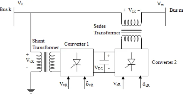
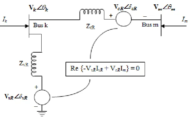
The UPFC is the most versatile FACTS controller for the regulation of voltage and power flow in a transmission line. Its modeling and integration for power flow studies were reported in [9] and [23]. For convenience the schematic diagram and equivalent circuit of UPFC referred from [23] is reproduced in Fig. 1 and Fig 2 respectively. It consists of two voltage source converters (VSC) one shunt connected and the other series connected both sharing a single capacitor as shown in Fig 1.
[image:2.595.142.454.457.621.2]Figure 2. Equivalent Circuit of UPFC
The voltage sources are
(1)
Where is the controllable shunt voltage magnitude is the controllable shunt voltage angle
is the controllable series voltage magnitude is the controllable shunt voltage angle is the shunt voltage source
is the series voltage source
Depending on the value of the mode of power flow control is determined. If the terminal voltage has to be regulated then should be in phase with the nodal voltage angle . If the phase angle difference between and is 90o then it controls active power, acting
as a phase shifter. If is in 90o with the angle of line
current, then it acts as a variable series compensator. On the other hand the magnitude of determines the amount of power flow to be controlled.
2.2. Overview of ACO Algorithm
Ant Colony Optimization [18]-[20] is based on the natural behavior of ants which live together in colonies. This approach is one among the viable method for stochastic combinatorial optimization. The main characteristic of this model is positive feedback, distributed computation and the use of a constructive greedy heuristic. A simple ACO algorithm for finding the best possible route (in terms of shortest distance) is given below
Initialization
The number of nodes , total number of Ants ,
counters for time and number of cycles , initial pheromone value at every edge and change in pheromone are initialized.
Then calculate the visibility factor . Later all the ants are randomly placed at every node creating a tabu list. Ant Cycle
Move each ant from the corresponding node to node with the probability as given in (2.3)
(2)
where and are parameters that control the relative importance of trial versus visibility.
Enter the node in tabu list and repeat this process for nodes.
Repeat the above process and fill the tabu list for all ants.
Pheromone Updating
Compute the length of the tour described by each ant. Then update the change in pheromone level at every edge with the tour described by the ant i.e. as given below
(3)
where ‘ ’ is a constant and hence
(cos
sin
)
(cos
sin
)
vR vR vR vR
cR cR cR cR
E
V
j
E
V
j
δ
δ
δ
δ
=
+
=
+
vR V vRδ
cRV
cRδ
vR E cRE
cRδ
cRδ
kθ
cRδ
θ
kcR
δ
cR
V
AS
'n ' 'm 'AS
'
AS
't
'NC 'ASij
' '
τ
'i-j'
ij
'
∆
τ
'
ij
η
'i'
'j'
P
ASijk( )
t
( ) ( ) ( ) ( ) ( ) k ij k ij allowed
if j allowed
ij k ASij ij k t t P t t t α β α β τ η τ η ∈ = ∈
∑
' '
α
' '
β
'j'
AS
(n - 1)
AS 'm '
'i-j'
k
thk 'L ' 0 k k k ij
Q if (i,j) tour described by tabu L otherwise τ ∈ ∆ = Q k ij
=
ij+
ijτ
τ
τ
[image:3.595.148.454.83.277.2]64 Optimal Location and Parameter Settings of UPFC Using ACO for Enhancing Power System Security under Single Contingencies
For every edge compute the new pheromone level using the formula
(4) where ‘ ’ is the evaporation coefficient. Thus the trace of ants is updated and the above process is repeated for
cycles after emptying the tabu list. The best route at the end of cycles is the shortest route.
2.2.1. Power System Security with UPFC Using ACO In this paper the problem of power system security considers the mitigation of transmission lines overload and the voltage deviations within the proper limits, under N-1 contingency conditions. Hence the objective function from [24] is as given below
(5) Where is the complex apparent power flow in the transmission line
is the maximum permitted MVA limit is the total number of transmission lines
is the deviation in voltage given by
is the minimum allowed voltage is the maximum allowed voltage is the voltage at bus
Subject to Equality Constraints
(6)
(7)
Equ (6) and (7) is valid for all buses except for buses connecting lines in which UPFC is installed. The equality constraints for the line in which UPFC is connected are given in [10]. Further, the inequality constraints for all the power system components including UPFC is given below Inequality Constraints (8) (9) (10) (11) (12) (13) (14) Where is the real power of generator
is the reactive power of generator is the tap ratio of th transformer
2.2.2. Implementation of ACO for UPFC to Enhance Power System Security
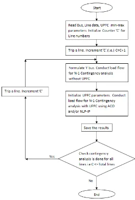
The flow chart for the proposed algorithm of ACO for optimal location and parameter setting of UPFC to enhance power system security is given in Fig 3. From figure it is evident that initially all data including bus, line UPFC parameters, constraints etc are given as input. Then for each line outage, both base case (without UPFC) and security enhanced case (with UPFC) using ACO and NLP-IP is performed to minimize the objective function (1). The results are saved and the same process is done for all transmission lines.
ij AS
(t +n) . (t ) +
ij AS ijτ
=
ρ τ
∆
τ
ρ
'NC 'AS
'NC 'AS
(
)
2 2
1 ,max 1
( ) NL tl Nbus
tl v i
tl
tl i
S
Min F W W V
S ∆ = = = +
∑
∑
tl S tl ,max tl S NL i V ∆ 0,min ,min
,min
,min ,max
,max ,min ,max
i
Vref Vi if Vi Vref
Vref
V if Vref Vi Vref
Vi Vref if Vref Vi
Vref ∆ − <
= < <
− < ,min Vref ,max Vref
Vi
i 0 bus NGi Di i ij j ij i j
j=1
bus
P - P - V Y V cos(θ -δ δ )
for i = 1,2,3,...,N ; i slackbus
+ = ≠
∑
0 bus NGi Di i ij j ij i j
j=1
bus
Q - Q - - V Y V sin(θ -δ δ )
for i = 1,2,3,...,N ; i slackbus;i P-V bus
+ = ≠ ≠
∑
min maxGi Gi Gi
P
≤
P
≤
P
min max
Gi Gi Gi
Q
≤
Q
≤
Q
min max
k k k
T
≤
T
≤
T
min max
vR vR vR
V
≤
V
≤
V
min max
cR cR cR
V ≤ V ≤ V
min max
vR
vR vR
δ
≤
δ
≤
δ
min max
cR
cR cR
δ
≤
δ
≤
δ
Figure 3. Flow chart for security enhancement using ACO with UPFC
3. Simulation Results and Discussion
This section presents the results of Enhancement of Power System Security with UPFC using ACO algorithm. The proposed approach is tested with IEEE 6 and IEEE 14 bus test system. To validate the results, they are compared with that of results obtained using Non Linear Programming – Interior Point (NLP-IP) method. The data for IEEE 6 and IEEE 14 bus system are considered from [24] and [25]-[26] respectively. Load flow programs are executed in MATLAB using MATPOWER [27] coding in INTEL core 2 Duo CPU T5500@ 1.66 GHz processor under Windows XP professional operating system.
The control parameter values for the ACO algorithm are: Number of Ants = 50; Number of cycles =300; Pheromonone update constant = 20, Exploration constant = 1; Global pheromone decay rate = 0.9; Local pheromone decay rate = 0.5; pheromone sensitivity = 1; visibility sensitivity = 5.
The simulation results for the test systems are classified into two cases: Case 1: IEEE 6 bus and Case 2: IEEE 14 bus.
3.1. Case 1: IEEE 6 Bus System
The IEEE 6 bus system consists of 3 generators, 11 transmission lines. There are 11 N-1 contingencies. The results of performance index and ranking based on overloaded lines and bus voltage violations for all N-1 contingencies are given in Table 1.
The Performance Index (PI) is the sum of Number of Over Loaded Lines (OLL) and the number of Voltage Violation buses (VV).
Line outage 8, 9 are ranked 1, line outage 2, 3, 5 are ranked 2 whereas line outage 1, 6, 7 are ranked 3. The base case (i.e. without UPFC) and security enhanced case (with UPFC) with optimal location and parameter settings for critical contingencies are performed and the results are tabulated in Table 2.
[image:5.595.163.427.76.468.2]66 Optimal Location and Parameter Settings of UPFC Using ACO for Enhancing Power System Security under Single Contingencies
Table 1. Rank for N-1 Contingency Analysis of Case 1
Legend: OLL: Over Load Line, VV: Voltage Violation, PI: Performance Index
Table 2. Security Enhancement Analysis of Case 1
Without UPFC With UPFC
ACO NLP-IP
Outage
Line OLL % LL VV location UPFC settings UPFC OLL % LL VV location UPFC settings UPFC OLL %LL VV
8 3 5 6 9
112.57 103.49 110.83 106.45
- Line 10 Vvr=1.0493 Vcr=0.001 3 100.47 - Line 5 Vvr=1.001 Vcr=0.001 2 3 9
115.31 127.06 129.64 -
9 3 5 6
106.59 100.74
101.11 Bus 6 Line 10 Vvr=1.0341 Vcr=0.1254 7
117.68 Bus
6 Line 6 Vvr=1.039 Vcr=0.001 2 3 103.68 133.44 Bus 6
2 1 3 5
163.53 138.72
162.97 - Line 9
Vvr=1.0543 Vcr=0.1254
1 3 5
158.39 135.15
116.71 - Line 7
Vvr=1.054 Vcr=0.012
1 3 5
165.31 148.84 173.79 -
3 1 2 6
137.57 108.32
117.21 - Line 10 Vvr=1.0500 Vcr=0.001 1
2 133.51 105.68 - Line 5 Vvr=0.989 Vcr=0.001 1 2
129.01 120.95 -
5 2 6 155.48 102.34 Bus 4 Line 9 Vvr=1.0500 Vcr=0.001 2 113.08 - Line 2 Vvr=1.181 Vcr=0.067 2 6 133.71 130.02 Bus 4
1 2 3 105.40 121.82 - Line 9 Vvr=1.0500 Vcr=0.001 2 3 101.70 118.01 - Line 3 Vvr=0.949 Vcr=0.001 2 3 117.08 127.92 -
6 3 5 111.12 101.79 - Line 10 Vvr=1.0500 Vcr=0.001 3 102.62 - Line 7 Vvr=0.990 Vcr=0.001 3 5 133.89 111.80 -
7 3 9 105.66 125.36 - Line 10 Vvr=1.0274 Vcr=0.001 3 9 101.55 120.37 - Line 10 Vvr=0.997 Vcr=0.001 3 9 109.83 131.70 -
Legend: OLL: Over Load Line, %LL: Percentage Loading in Line VV: Voltage Violation
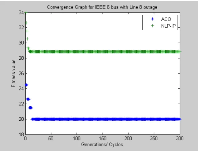
Similarly for other line outages with UPFC the number of overloaded lines and the percentage of overloading is lesser when compared to the case without UPFC. To validate the proposed ACO based security enhancement it is compared with NLP-IP method which is also furnished in Table 2. In all the cases the proposed method has obtained better optimal points when compared to the traditional NLP-IP method. As a sample case the convergence graph for Case 1 with line 8 as outage using ACO and NLP-IP is shown in Fig 4.
Outage line From Lines OLL VV PI = OLL+VV Rank
Bus To Bus Line No. Total Bus No. Total
1 1 2 2,3 2 - 0 2 3
2 1 4 1,3,5 3 - 0 3 2
3 1 5 1,2,6 3 - 0 3 2
4 2 3 - - - 0 0 -
5 2 4 2,6 2 4 1 3 2
6 2 5 3,5 2 - 0 2 3
7 2 6 3,9 2 - 0 2 3
8 3 5 3,5,6,9 4 - 0 4 1
9 3 6 3,5,6 3 6 1 4 1
10 4 5 - 0 - 0 0 -
[image:6.595.70.535.338.607.2]Figure 4. Convergence Graph for Case 1 IEEE 6 Bus with Line 8 Outage
3.2. Case 2: IEEE 14 Bus System
[image:7.595.136.460.78.326.2]The IEEE 14 bus system consists of 5 generators, 20 transmission lines. There are 20 N-1 contingencies. The results of performance index and ranking based on overloaded lines and bus voltage violations for all N-1 contingencies are given in Table 3.
Table 3. Rank for N-1 Contingency Analysis of Case 2
Outage line Lines OLL VV PI = OLL+VV Rank
From Bus To Bus Line No. Total Bus No. Total
1 1 2 2,5,7 3 12 1 4 1
2 1 5 1,5 2 [1] 12 1 3 2
3 2 3 5,6,7 3 12 1 4 1
4 2 4 5 1 12 1 2 3
5 2 5 - 0 12 1 1 4
6 3 4 - 0 12 1 1 4
7 4 5 - 0 12 1 1 4
8 4 7 - 0 12 1 1 4
9 4 9 - 0 12 1 1 4
10 5 6 7 1 7,12 2 3 2
11 6 11 - 0 12 1 1 4
12 6 12 - 0 - 0 - -
13 6 13 - 0 - 0 - -
14 7 8 No feasible solution
15 7 9 - 0 7 1 1 4
16 9 10 - 0 12 1 1 4
17 9 14 - 0 12 1 1 4
18 10 11 - 0 11,12 2 2 3
19 12 13 - 0 12 1 1 4
20 13 14 - 0 12,13 2 2 3
[image:7.595.72.526.423.720.2]68 Optimal Location and Parameter Settings of UPFC Using ACO for Enhancing Power System Security under Single Contingencies
From Table 3 it is understood that there are two rank 1 and rank 2 contingencies and three rank 3 contingencies. Hence for Case 2 IEEE 14 bus system for rank 1, 2 and 3 alone security enhancement with UPFC is done and the results are tabulated in Table 4.
From Table 4, it is evident that for line outage 1, without UPFC the overloaded lines are 2,5 and 7 and with UPFC the overloaded lines are line 2,5,7 but with lesser over all overload percentage.
[image:8.808.94.723.184.400.2]In this case both the proposed method ACO and conventional NLP-IP obtains the same optimal points. For line outage 3, the over loaded lines without UPFC are 5, 6, 7 whereas with UPFC using ACO the overloaded lines are 4, 5, 6 and with NLP-IP is 5,6 and 7. In this case also the overall overloading is lesser with the proposed method when compared to that of NLP-IP.
Table 4. Security enhancement analysis of Case 2
Without UPFC With UPFC
ACO NLP-IP
Outage
Line OLL % LL VV UPFC location UPFC settings OLL % LL VV UPFC location UPFC settings OLL %LL VV
1 2 5 7
264.82 108.3214
6.68 Bus 12 Line 9
Vvr=1.020 Vcr=0.001
2 5 7
263.11 100.12
148.59 Bus12 Line 9
Vvr=1.020 Vcr=0.001
2 5 7
263.11 100.12
148.59 Bus12
3 5 6 7
138.65 106.37
103.13 Bus 12 Line 6
Vvr=0.984 Vcr=0.001
4 5 6
114.76 115.65
108.52 Bus12 Line 7
Vvr=0.985Vcr =0.001
5 6 7
139.55 108.52
100.26 Bus12 2 1 5 121.51 156.75 Bus 12 Line 10 Vvr=1.003 Vcr=0.001 1 5 121.59 157.37 - Line 10 Vvr=0.978Vcr=0.001 1 5 121.59 157.37 -
10 7 100.13 Bus7 Bus12 Line 10 Vvr=1.059 Vcr=0.001 - - - Line 10 Vvr=0.984Vcr=0.001 - - -
4 5 134.30 Bus 12 Line 6 Vvr=0.995 Vcr=0.001 3 5 103.73 119.47 Bus 12 Line 5 Vvr=0.978Vcr=0.001 5 133.87 Bus12
18 - - Bus11 Bus12 Line 7 Vvr=0.977 Vcr=0.001 - - Bus 11 Bus 12 Line 11 Vvr=1.091Vcr=0.001 - - -
20 - - Bus12 Bus13 Line 7 Vvr=0.951 Vcr=0.001 - - Bus 12 Line 7 Vvr=1.050Vcr=0.001 - - -
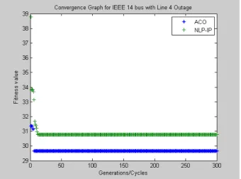
Figure 5. Convergence Graph for Case 2, IEEE 14 bus with Line 4 Outage
4. Conclusions
In this paper, the ACO algorithm is proposed for enhancing power system security using UPFC. The proposed method shows the ability of finding optimal parameters for UPFC location and settings to mitigate the power system security problem. The simulation studies carried out on both
IEEE 6 bus and IEEE 14 bus reveals that the proposed method in most cases solves the problem of line overloading and bus voltage violation and in some cases reduces the percentage level of overloading in the lines. To validate the ability of proposed method it has been compared with the conventional NLP-IP method and the results indicate that the proposed method is superior in all cases.
REFERENCES
B. Stott, O. Alsac, A. J. Monticelli. “Security Analysis and [1]
Optimization”, Proceedings of the IEEE, Vol. 75, No. 12, December 1987, pp. 1623-1644.
J. A. Huang, A. Valette, M. Beaudoin, K. Morison, A. [2]
Moshref, M. Provencher, J. Sun. “An Intelligent System for Advanced Dynamic Security Assessment”, Proceedings of the IEEE PowerCon 2002, International conference on power system technology, 13-17 Oct. 2002, pp. 220-224. Ghamgeen I. Rashed, H. I. S habeen, and S. J. Cheng, [3]
“Optimal location and parameter setting of TCSC by both Genetic Algorithm and Particle Swarm optimization”, Proc. Of 2nd IEEE Conference on Industrial Electronics and
Applications, 2007, pp. 1141-1147
Hingorani, N. G. 'Flexible AC Transmission', IEEE [4]
Spectrum, pp.40 - 44, April 1993.
X. P. Zhang, C. Rehtanz, and B. Pal, Flexible AC [5]
Transmission Systems: Modelling and Control. New York: Springer, 2006.
G.D. Galiana et al, “Assessment and control of the impact [6]
of FACTS devices on power system performance”, IEEE Trans on Power System, Vol. 11, No. 4, pp. 1931-1936, Nov. 1996.
H. Shayeghia, H.A. Shayanfarb, S. Jalilzadehc, A. Safari, [7]
“A PSO based unified power flow controller for damping of power system oscillations”, Energy Conversion and Management, Vol. 50, Issue 10, Oct, 2009, pp. 2583–2592 Mohan Mathur,R.,and Rajiv K.Varma, “Thyrisor Based [8]
FACTS Controllers for Electrical Transmission Systems”, IEEE Press Series on Power Engineering, John Willy & Sons, Inc. Publication, New York, 2002.
L. Gyugyi, "Unified Power Flow control concept for [9]
Flexible AC Transmission Systems", IEE Proceedings-C, Vo1. l39, No. 4, July 1992.
C. R. Puerle-Esquivel and E. Acha, “A Newton-type [10]
algorithm for the control of power flow in electrical power networks,” IEEE Trans. Power System, Vol. 12, no. 4, pp. 1474-1480, Nov. 1997
Rashed, G.I.; Sch. of Electr. Eng., Wuhan Univ., Wuhan, [11]
[image:9.595.129.470.80.332.2]70 Optimal Location and Parameter Settings of UPFC Using ACO for Enhancing Power System Security under Single Contingencies
Esmaeil Ghahremani and Innocent Kamwa, “Optimal [12]
Placement of Multiple-Type FACTS Devices to Maximize Power System Loadability Using a Generic Graphical User Interface”, IEEE Trans. Power System, Vol. 28, No. 2, May 2013, pp 764-778.
Shaheen, H.I., Rashed, G.I; Cheng, S.J., “Optimal Location [13]
and Parameters Setting of Unified Power Flow Controller Based on Evolutionary Optimization Techniques”, IEEE Power Engineering Society General Meeting, June 24-28, 2007, pp. 1 – 8.
Biplab Bhattacharyya, Vikash Kumar Gupta and Sanjay [14]
Kumar “UPFC with series and shunt FACTS controllers for the economic operation of a power system” Ain Shams Engineering Journal Vol. 5, Issue 3, Sept. 2014, pp. 775– 787
Arabkhaburi, D.,Kazemi, A., Yari, M. and Aghaei, J., [15]
“Optimal Placement of UPFC in Power Systems Using Genetic Algorithm”, IEEE International Conference on Industrial Technology,( ICIT), 15-17 Dec. 2006, pp.1694 – 1699.
Hamid, Z., Musirin, I., Othman, M.M. and Khalil, M.R., [16]
“Optimum tuning of Unified Power Flow Controller via Ant Colony Optimization technique”, 4th International Power Engineering and Optimization Conference (PEOCO), 23-24 June 2010, pp.170 – 177.
Shwetasinghal, Shivangigoyal, Shubhragoyal and [17]
Divyabhatt, “A comparative study of a class of Nature Inspired Algorithms”, Proceedings of the 5th national conference :INDIACom, March 10-11, 2011
Dorigo, M., Maniezzo, V., and Colorni, A., Ant System:‚ [18]
“Optimization by a colony of cooperating agents”, IEEE Trans. Syst., Man, and Cybern.”,Vol. 26, Issue 1, Feb 1996, pp. 29-41.
Dorigo, M. and Gambardella, L. M., “Ant Colony System: [19]
A cooperative learning approach to the traveling salesman problem”, IEEE Transaction on Evolutionary Computation, Vol 6, No.4, 1997, pp. 317-365.
Dorigo M. and Di Caro G., “The Ant [20]
ColonyOptimization-Meta-heuristic”, Ei David Corne, Marco Dorigo and Fred Glover, editors, New Ideas in Optimization, McGraw-Hill, London, 1999, pp. 11-32. Prakash Burade, Jagdish Helonde, “Optimal Location of [21]
FACTS Device on Enhancing System Security”, International Journal of Scientific & Engineering Research, Vol 3, Issue 5, May-2012, pp. 1-7.
Florain A. Porta and Stephen J Wright, “Interior point [22]
methods,” Journal of Computational and Applied Mathematics, Elsevier, Vol. 124, No. 1-2, Dec 2000, pp. 281–302.
A. Nabavi-Niaki and M.R. Iravani, “Steady-state and [23]
Dynamic Models of Unified Power Flow Controller (UPFC) for Power System Studies”, IEEE Trans. Power Systems Vol. 11, No 4, Nov 1996, pp. 1937–1943.
Mehrdad Tarafdar Hagh, Manijeh Alipour, Saeed [24]
Teimourzadeh, “Application of HGSO to security based optimal placement and parameter setting of UPFC”, Energy Conversion and Management, Vol. 86, July 2014, pp. 873– 885.
http://www.ee.washington.edu/research/pstca/ [25]
S. Kalyani and K. Shanti Swarup, “ Study of Neural [26]
Network Models for Security Assessment in Power Systems”, International Journal of Research and Reviews in Applied Sciences, Vol. 1, No. 2, Nov 2009, pp. 104-117. R. D. Zimmermann and Carlos E. Murillo-Sánchez, [27]