Numerical Studies of Twisted Vaned Diffuser on the
Performance of a Centrifugal Compressor Stage
P.Venkateswara Rao
*, G.V.Ramana Murty, G. Venkata Rao
Dept. of Mechanical Engineering, Vasavi College of Engineering, Hyderabad 500031 *Corresponding Author: [email protected]
Copyright © 2014 Horizon Research Publishing All rights reserved
Abstract
This paper examines the effect of twist in diffuser vane from hub to shroud on the performance of an industrial centrifugal compressor stage. The chosen diffuser has an aerofoil section with varying blade chord from hub to shroud due to blade twist or in other words, the solidity of the diffuser blade is varied from hub to shroud. The twisting is given to the diffuser blade by rotating the diffuser blade opposite to the direction of rotation of the impeller keeping its leading edge as origin resulting in different stagger angles from hub to shroud. The analysis was conducted at an impeller tip Mach number of 0.35. The overall stage performance is evaluated in terms of head coefficient, stage efficiency and power coefficient of the stage and static pressure recovery coefficient of diffuser vanes for different diffuser vane twist angles with varying flow coefficients. The observed optimum twist for the best performance is 9° for the chosen impeller diffuser configuration.Keywords
Diffuser, Twist, Stagger Angle, Solidity, Efficiency, Static Pressure Recovery Coefficient1. Introduction
The wide range of demands on centrifugal compressors bring out the need to address many design and constructional aspects to achieve a machine which is compact, efficient and is competitive in the market. The conventional approach to evaluate a turbo machine performance and its model testing becomes costly and time consuming. Computational fluid dynamics (CFD) has become a cost effective tool for predicting the performance of turbo machine and also for predicting detailed flow information inside the turbo machine to enable the selection of best operating condition.
Non-uniform flow at the exit of the centrifugal impeller mixes in the vaneless space of the diffuser causing a rise in static pressure as well as significant loss of total pressure. These mixing losses are usually an important source of inefficiency. Centrifugal impeller flows investigated by number of researchers have confirmed the existence of separated zones at the exit of the impeller, which limit the
impeller diffusion. Therefore, it is necessary to develop methods which reduce the energy losses associated with diffusion and also increase the stable operating ranges of diffusion systems.
The diffuser has to convert as much of the kinetic energy as possible into pressure energy. With radial compressors, about half of the energy imparted to the fluid in the rotor resides in the outflow velocity. Various diffuser types are employed, depending on the application and the design. A basic distinction is made between vaneless and vaned diffusers. Subsequently Low Solidity Vaned Diffusers (LSVD) have come into existence to overcome the deficiencies of vaneless and vaned diffusers.
2. Literature Review
The first reference to low solidity vaned diffuser was in a Japanese patent by Senoo and Kinoshita (1978). He found that the centrifugal stage had better performance with the LSVD than with the vaneless diffuser without any loss of flow range. Kaneki and Ohashi (1982) suggested that LSVDs were more suitable for low specific speed applications. This is because use of LSVD increase the flow angle and reduce the flow path length and, hence, the friction effects. Amineni(1996), Eynon and Whitfield (1997), Holweg W. C et al(1998), Siva Reddy et al. (2004, 2007), Oh et al. (2008) have studied the flow through Low solidity diffuser vane and concluded that the stage performance is affected by the setting angle, incidence angle, vane turning angle, solidity, number of vanes and impeller width have an effect on the performance of the stage based on their studies. Abdelwahab (2005, 2008) designed and introduced a three dimensional diffuser. This three dimensional airfoil diffuser prevents the development of sturdy secondary flows along the diffuser suction surface near the shroud and results in a more uniform blade loading.
diffuser vane is formed from a standard aerofoil profile with marginal modification in the trailing edge region. The hub profile is set at 24o setting angle with tangential direction and
shroud profile is twisted in the direction opposite to that of the impeller rotation to obtain a three dimensional diffuser with leading edge as the reference. As a result of the profile rotation to form the twist, the chord length varies from hub to shroud to ensure that the TE of all the sections is lying on the same radius with respective to centre of impeller. In the present analysis, studies were conducted with twist angles ranging 5o to 11o insteps of 2o for the chosen impeller. For all
the above said considerations the impeller tip Mach number is 0.35. In the present study, the profile chosen for the diffuser vane is an uncambered aerofoil section where as Abdelwahab (2005, 2007) studied on cambered profile providing the twist in the same direction of rotation as that of impeller.
3. Centrifugal Compressor Details
For the present work a low speed industrial compressor stage is selected. The specifications of the compressor are given in Table 1. The study is conducted at five different flow coefficients. These are design mass flow rate, two at below design mass flow rate (80 % and 90%) and two above design mass flow rate (110% and 120%).
Table 1. Details of the Compressor stage
Speed, n 4500rpm
Impeller radius at inlet(r1) 150 mm Impeller outlet radius (r2) 250mm Blade angle at impeller inlet, β1 27o Blade angle at impeller exit, β2 45o Width of the diffuser passage, b 24.5mm
Mass flow, m 1.3 kg/s
Diffuser blade chord length at hub, l 100mm
Number of Impeller blades, z 17
Number of Diffuser blades 14
4. Computational Details: Geometry
and Mesh
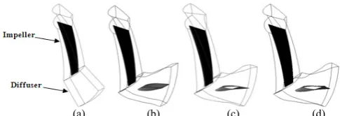
Modeling of the geometry is done using Autocad and vertex data is exported to ANSYS Turbo Grid to descretize impeller and vaned diffuser grid. Vaneless diffuser grid is modeled using GAMBIT software. These are done with the assumption that flow is periodic in each diffuser vane passage. This avoids the necessity of modeling the entire centrifugal compressor stage, thereby saving enormous computational time and resources. Figure 1 shows the geometry of the configurations used for the analysis.
(a) (b) (c) (d)
Figure 1. Geometry details of the Compressor Stage, impeller with a) VLD b) LSVD c) TVD (Twisted Vane Diffuser) constant chord d) TVD variable chord
[image:2.595.311.554.82.165.2]Structured hexahedral grids are generated using ANSYS Turbo Grid using O - grid and C - grid topology around the diffuser and impeller blades to improve the grid quality around the leading edge and trailing edges of the blades. Grid independent studies for impeller and compressor stage are done on an individual basis at design flow condition. Grids are generated in the increasing number of elements from Grid 1 to Grid 4. Grid 4 is taken as the reference and compared with other three grids. The percentage differences are shown in Table 2. The differences are considerably less for Grid 3 as compared to Grid 1 and 2. In all simulations the employed mesh has an average y-plus of about 6.
Table.2. Grid independence study for impeller with 9o twist variable chord vaned diffuser
Diffuser Vane
Setting Angle Number of Elements Cp % difference
24o
Grid1 17024 0.2168925 0.7231123 Grid2 19152 0.2174509 0.4675192 Grid3 20088 0.2184418 0.0139606
Grid4 25110 0.2184723 -
For the analysis of the compressor stage, mixing plane interface is used in between the outlet of the impeller and inlet to the diffuser. Though transient Rotor-Stator model accounts for all interaction effects between components that are in relative motion to each other, the principal disadvantage of this method is that the computer resources required may be large, in terms of simulation time, disk space and quantitative post processing of the data. So the mixing model stage interaction is selected. This model allows steady state predictions to be obtained for multi-stage machines. A finite volume approach is used, to discretize the governing equations, which ensures conservation of mass, momentum and energy over any region of computational domain.
4.1. Boundary Conditions and Numerical Methodology
[image:2.595.308.554.379.484.2] [image:2.595.59.298.420.592.2]axially at the inlet. The reference absolute pressure used for simulation is 95000 Pa, and hence the relative pressure at the inlet is given as zero Pascal. The fluid used for simulation is air and assumed as an ideal gas. The specified heat transfer model used for the simulation is the total energy model. The total temperature at the inlet duct is 310 K. The turbulence model is standard k-ε model and the turbulence intensity is selected as 0.05 and Eddy length scale as 0.03 m. This is in line with the computations carried out by Tarek Meakhail and Seung O Park (2004) on a centrifugal fan. The side walls of the impeller domain and diffuser domain are specified as rotational periodic boundaries. At the outlet, mass flow rate is mentioned.
The fluid time step is given as 0.1/ω, where ω is the angular velocity in rad/s. All the governing equations are solved till 1e-05 residual error.The solution time is varied depending upon the mass flow rate. Post processing of data was carried out resulting in fringe plots for better understanding of fluid flow through the chosen centrifugal compressor stage.
5. Results and Discussions
The simulations are done at an instantaneous relative position of impeller and diffuser. An assumption in such a simulation is that the flow inside a diffuser passage does not vary with the relative position of impeller and diffuser. The results of computation carried out for the centrifugal compressor stage with vaneless diffuser, LSVD are compared with experimental studies on the same configuration obtained by the Siva Reddy, T et. al (2004) for establishing the selected numerical model. CFD results are in well agreement with the experimental results. For reasons of brevity the comparison is not shown here.
The results of computation carried out for the centrifugal compressor stage with vaneless diffuser, LSVD and twisted vane diffuser are presented and compared in the following sections.
5.1. Stage Performance Analysis – Effect of Twist
The subsequent figures show the variation of normalised property with respect to normalized flow coefficient for various twist angles for a chosen setting angle 24o. The
performance of the stage with the chosen types of diffuser is plotted, showing the stage efficiency, head coefficient and power coefficient in a normalized form, normalization carried out with reference to the data of a vaneless diffuser at the design point. The normalized flow coefficient variation is studied from 0.80 to 1.20.
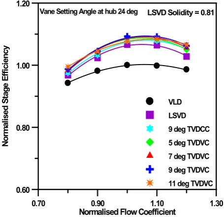
5.1.1. Stage Efficiency
Centrifugal compressor stage performance is evaluated by means of stage stage efficiency. The stage efficiencies are evaluated based on the conditions at the impeller domain inlet and diffuser domain outlet. Hence, this accounts for the
combined performance of the impeller and diffuser. Figure 2 shows variation of stage efficiency for different diffusers with respect to flow coefficient at different twist angles. At design flow coefficient (i.e. φ = 0.053) maximum efficiency is observed for 9o twist with variable chord
configuration, and it is 1.32% higher when compared to that of 9o twist with constant chord and 2.5% more than the
LSVD. As the twist angle is increased from 5o to 9o the
efficiency is also increasing for all the chosen flow coefficients. But for the 11o TVDVC, efficiency falls for all
considered flow coefficients expect at high flow coefficient compared to 9o TVDVC. The increase in efficiency with
twist angle may be attributed to the reduction of secondary flows. For 9o TVDVC at below design flow 1.26% increment
is observed and at high design flow, efficiency increases by 1.17% when compared with 9o TVDCC. For all the twist
angles the peak efficiency is observed at design flow point. From the below figure it is also observed that the same trend is continued for all the twist angles with variable chord. By twisting with variable chord the performance of the compressor stage is improved in terms of operating range and compressor stage efficiency for all twist angles.
[image:3.595.319.547.349.569.2](TVDVC – Twisted Vane diffuser with variable chord
Figure 2. Variation of normalised stage efficiency
5.1.2. Head Coefficient
Static head gives an amount of static pressure rise from impeller inlet to the diffuser outlet. The variation in normalized head coefficient with flow coefficient is shown in Fig.3 for the chosen setting angle 24o, with variable chord
twist 5o to 11o. It is observed from the figure that the
performance has improved in terms of head coefficient with the increasing twist from 5o to 9o over twist with constant
chord and LSVD. But for twist 11o head coefficient is
decreased compared to twist 9o at design flow. The decrease
in head rise at lower flow coefficients is likely to be a result of increased losses and flow recirculation. At 9o twist with
0.70 0.90 1.10 1.30
Normalised Flow Coefficient
0.60 0.80 1.00 1.20
No
rm
al
is
ed
S
ta
ge
E
ffi
ci
en
cy
variable chord a maximum head rise of 0.93 % is observed at design flow and an average of 0.49% improvement is observed at other flow rates considered compared with TVDCC
[image:4.595.76.281.132.331.2]TVDCC – Twisted Vane diffuser with Constant chord)
Figure 3. Variation of normalised head coefficient
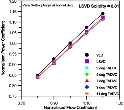
[image:4.595.327.535.284.481.2]5.1.3. Power Coefficient
Figure 4 shows the variation in normalized power coefficient with normalized flow coefficient. The value of power coefficient provides information about the energy required by the fluid as it passes through the impeller and diffuser. As the flow coefficient φ increases from 0.80 to 1.20, the power coefficient increases uniformly for all diffusers. The power coefficient of the LSVD is more than the twist with constant and variable chord vane diffuser configurations.
Figure 4. Variation of normalised power coefficient
The variation in power coefficient follows the general trend of the normal limiting characteristic for a backward curved bladed impeller. As seen from fig.4 the normalized power coefficients for twisted variable chord cases show a
marginal reduction of 0.05% at all flow coefficients. The decrease in power coefficient is increasing from 90% flow to 120% flow i.e. from 0.01 % to 0.07 but at 80% flow rate a marginal increment of 0.01% observed when compared with 9o twist with constant chord. An average decrement of
0.36 % is observed with LSVD. The effect of increase in twist angle with variable chord on power coefficient is insignificant.
5.1.4. Static Pressure Recovery Coefficient
Static pressure recovery coefficient (cp) describes the
amount of static pressure recovered from the available dynamic head at the diffuser inlet. Figure 5 shows the variation in static pressure recovery coefficient, Cp, against
the normalized flow coefficient,φ, for the chosen setting angle 24o by varying twist angle with variable chord from 5o
to 11o and compared with 9o twist constant chord.
Figure 5. Variation of static pressure recovery coefficient
For the case of variable chord with twist 5o to 9o, there is
increase in the pressure recovery at all flow rates where as for the twist angle 11o there is significant decrease in SPR
compared with 9o twist constant chord. A maximum of
3.47% static pressure recovery is observed at design flow, and an average of 2.33% increment is observed for the chosen flow coefficients compared with 9o twist constant
chord.
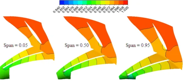
5.1.5. Static Pressure Variation in the Stage
Static pressure coefficient variation inside compressor stage is presented for twisted diffuser in this section in the form of contour plots. Static pressure coefficient is obtained by normalizing the local static pressure with the dynamic head based on the impeller blade exit velocity (
0
.
5
ρ
2u
22). Static pressure continuously increases inside the compressor stage from the impeller inlet to diffuser outlet. Contours of static pressure variation inside the compressor stage are shown in Fig.6 (a & b) at three different span-wise planes (S = 0.05, 0.5 and 0.95) corresponding to design flow for 24osetting angle for twist angles of 9o and 11o although results
available from 5o to 11o.
0.70 0.90 1.10 1.30
Normalised Flow Coefficient
0.80 0.85 0.90 0.95 1.00 1.05 1.10 No rm al is ed H ea d Co ef fic ie nt VLD LSVD 9 deg TVDCC 5 deg TVDVC 7 deg TVDCC 9 deg TVDVC 11 deg TVDVC
LSVD Solidity = 0.81
Vane Setting Angle at hub 24 deg
0.70 0.90 1.10 1.30
Normalised Flow Coefficient
0.75 0.80 0.85 0.90 0.95 1.00 1.05 1.10 1.15 1.20 No rm al is ed P ow er C oe ffi ci en t VLD LSVD 9 deg TVDCC 5 deg TVDVC 7 deg TVDVC 9 deg TVDVC 11 deg TVDVC
LSVD Solidity = 0.81
Vane Setting Angle at hub 24 deg
0.70 0.90 1.10 1.30
Normalised Flow Coefficient 0.00 0.10 0.20 0.30 St at ic P re ss ur e Re co ve ry C oe ffi ci en t VLD LSVD 9 deg TVDCC 5 deg TVDVC 7 deg TVDVC 9 deg TVDVC 11 deg TVDVC
LSVD Solidity = 0.81
[image:4.595.72.286.493.682.2]Figure 6(a). Contours of static pressure coefficient at three different span-wise locations for 24o SA, 9o twist Variable Chord at design flow
Figure 6(b). Contours of static pressure coefficient at three different span-wise locations for 24o SA, 11o twist Variable Chord at design flow In span-wise direction variation in static pressure is
marginal as can be seen from figure. It may be observed from these figures that the static pressure recovery is appreciable for 9o twist as against 11o which is conformed from the
performance plots as well. Regions of low pressure are observed on pressure surface for 11o twist angle where as no
such region is seen for 9o twist.
6. Conclusions
Numerical investigations have been conducted on the chosen stage of an industrial centrifugal compressor to establish the efficacy of using twisted vanes with variable chord instead of twisted vanes with constant chord and low solidity vaned diffuser for improving the performance. The study indicated that the performance of the stage can be improved with the use of twisted diffuser vanes with variable chord. It is concluded from the present study that the twist angle with variable chord has an effect on the performance of the chosen stage. The relative improvement in performance in terms of efficiency, head rise and static pressure recovery is improved at all flow rates analyzed. From the analysis it can be concluded that 9o twist with variable chord shows
better performance for all the considered flows and by twisting the blade the range of operation is also improved for the chosen configuration. At 9o twist with variable chord an
improvement of 1.32% in the efficiency, 0.93% in head rise and 3.47% in static pressure recovery coefficient is observed when compared with 9o twist constant chord at design flow.
Power coefficient decreased very marginally, with an average decrement of 0.05% for the chosen flow rates.
Nomenclature
Cp Static Pressure Recovery Coefficient,
(p4-p2)/(0.5ρu22)
D diameter (m)
g acceleration due to gravity
H total head, (
RT
( )
PP g1 011
1
1
01 04
−−
−
γ γ
γγ m)
l Vane chord length(m) LE Leading edge
LSVD Low solidity vaned diffuser m mass flow rate(kg/s) n speed(rpm)
p pressure(Pa) r radius(m) R gas constant s pitch(m), πD3/Z
TVD Twisted Vaned diffuser u peripheral velocity,(πDn60m/s)
VLD Vaneless diffuser Z number of diffuser vanes α flow angle(deg)
β blade angle(deg)
η stage efficiency(%),
( )
1( )
101 04 1 1 4
− − −
T T P P γγ
λ power coefficient, φψ/η φ flow coefficient, m/(ρu2πD22/4)
γ ratio of specific heats ρ inlet density(kg/m3) σ solidity(l/s)
ψ head coefficient, H/(u22/2g)
[image:5.595.162.455.77.207.2] [image:5.595.160.456.233.336.2]0 total quantity 1 inlet of impeller 2 exit of impeller 3 inlet of diffuser 4 exit of diffuser
REFERENCES
[1] Abdelwahab, A. “On the Use of Three-Dimensional Airfoil-Shaped Vaned Diffusers with Industrial Centrifugal Compressors” 4th AIAA Theoretical Fluid Mechanics Meeting 6 - 9 June 2005, Toronto, Ontario Canada.
[2] Abdelwahab, A., Gordon, G., and Baker, R. Leaned centrifugal compressor airfoil diffuser. US Patent Application Disclosure 11/199252, August 2005.
[3] Abdelwahab, A., Gordon, G., and Baker, R. Airfoil diffuser for centrifugal compressor. US Patent Application Disclosure 11/903592, September 2007.
[4] Abdelwahab, A., and Gerber. G., “A new three-dimensional aerofoil diffuser for centrifugal compressors” J. Power and Energy, Proc. IMechE Vol. 222 Part A, 819-830 2008 [5] Amineni, N. K. and Engeda, A. Performance of low solidity
and conventional diffuser systems for centrifugal compressors. ASME paper no. 96-GT-155, 1996.
[6] Eynon, P.A., A. Whitfield, M.R. Firth, A.J. Parkes, and R.A. Saxton, Study of the flow characteristics in the inducer bleed slot of a centrifugal compressor ASME paper 96-GT-262, 1997.
[7] Oh, J., C.W. Buckley, and G.L. Agrawal, Numerical Investigation of Low solidity vaned diffuser performance in a High-Pressure Centrifugal Compressor: Part II-Influence of Vane Stagger. Paper no. GT2008-50178, 1487-1494, 2008. [8] Senoo,Y., Japanese patent application disclosure 119411 / 78,
October, 1978.
[9] Siva Reddy, T. Ch., Ramana Murty, G. V., Mukkavilli, P., and Reddy, D. N. Effect of the setting angle of a low-solidity vaned diffuser on the performance of a centrifugal compressor stage. Proc. Instn Mech. Engrs, Part A: J. Power and Energy, 2004, 218, 637– 646.
[10] Siva Reddy, T. Ch., Ramana Murty, G. V., Mukkavilli, P., and Reddy, D. N. Experimental studies on the effect of impeller width on centrifugal compressor stage performance with low solidity vaned diffusers”. Proc. Instn Mech. Engrs, Vol. 221 Part A: J. Power and Energy, 2007, 519-533. [11] Venkateswara Rao.P, G.V. Ramana Murty, “Effect of twist