International Journal of Emerging Technology and Advanced Engineering
Website: www.ijetae.com (ISSN 2250-2459, ISO 9001:2008 Certified Journal, Volume 3, Issue 6, June 2013)
Analysis of Power oscillations in Single Machine Infinite
Bus (SMIB) System and Design of Damping Controller
M. K. Bhaskar
1, Avdhesh Sharma
2, N. S. Lingayat
31Associate Professor, Department of Electrical Engg., MBM Engg. College, JNV University, Jodhpur-India 2
Professor, Department of Electrical Engg., MBM Engg. College, JNV University, Jodhpur-India 3Head, Department of Electrical Engg., Dr. B. A. T. University’s, I.O.P.E, Lonere-402103, Maharashtra-India
Abstract—The paper deals with analysis of loading conditions on damping torque coefficient and synchronizing coefficient in SMIB system and design of Delta-Omega type of damping controller for damping of power oscillations in the system. Effect of variation of loading on synchronizing torque and damping torque coefficients has been investigated in detail. A new design approach for optimizing the parameters of Delta-Omega type damping controller has been presented. The dynamic performance of the system with optimum Delta-Omega type damping controller has been investigated and found quite robust over a wide variation in loading condition.
Keywords— Single Machine Infinite Bus System (SMIB), Small Signal Stability, Delta-Omega Power System Stabilizer, Damping Controller.
I. INTRODUCTION
In modern days, the trend is to achieve economies in system design, by having larger size units and higher per unit reactance of generating and transmission equipment. So more emphasis is being placed on controls of the system to provide the required compensation to offset the inherent reduction in stability margins because of these new trends in equipment design. High gain excitation system with power system stabilizer as damping controller has extensively used in power system as an effective means of enhancing overall system stability.
To provide effective damping to power oscillations, the stabilizer must produce a component of electric torque, which is in phase with speed deviation. The transfer function of the stabilizer must compensate for the gain and phase characteristics of the excitation system, the generator and the power system, which collectively determine the transfer function, GEP(s), from the stabilizer output to the component of electrical torque which can be modulated via excitation control.
The AVR gain plays a major role in system stability [1-3]. The damping torque coefficient and synchronizing torque coefficient are dependent on selection of AVR gain. Moreover the behavior of these coefficients varies with variation in loading [4]. As far as known to authors, the effect of variation in loading condition on damping and synchronizing torque coefficient has not been investigated in detail. For small signal stability, both damping and synchronizing torque coefficients should be positive for all possible loading conditions.
Two types of damping controller i.e. Delta-Omega PSS and dual input PSS are commercially available to install at generating station on synchronous generator [5-7]. In this paper, a new approach for designing the damping controller is presented and the performance of Delta-Omega PSS has been investigated in detail to understand its behavior on different loading conditions. Selection of damping ratio for designing damping controller is another area of concern as a damping ratio for electromechanical mode may result in damping controller gain, which adversely affects the exciter mode of the system.
In view of above, the main objectives of the research work presented in this paper are:
1. To develop a small perturbation dynamic model of a
single machine infinite bus system in state-space form.
2. To study the effect of loading conditions on
International Journal of Emerging Technology and Advanced Engineering
Website: www.ijetae.com (ISSN 2250-2459, ISO 9001:2008 Certified Journal, Volume 3, Issue 6, June 2013)
[image:2.612.69.572.132.331.2]ref
v
1v
AK
Exciter fd E do 3 T s 1 K circuit Field fd
2K
6K
4K
eP
mT
5K
R sT 1 1 t E Transducer Voltage D K Hs 2 1 1K
s
0
G (s)
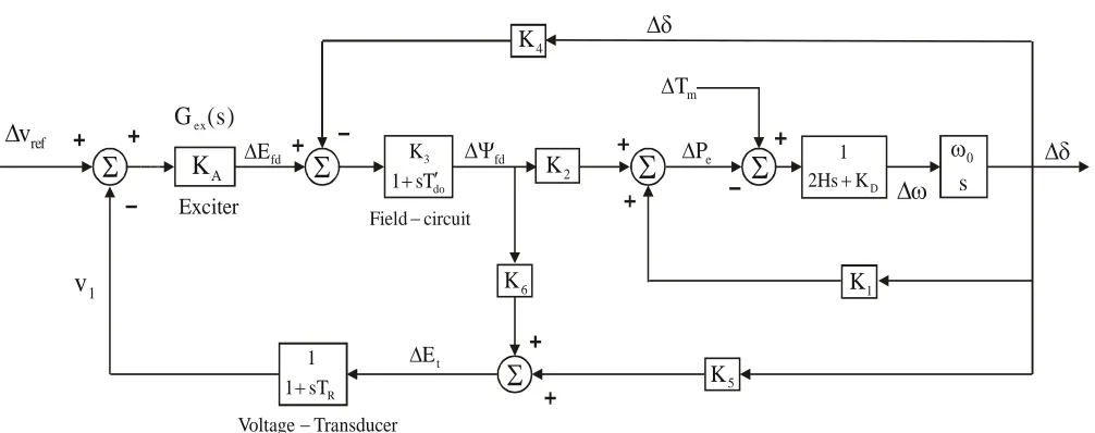
exFig. 1 : Transfer Function Block Diagram of a SMIB System with AVR
3. To present a systematic approach for designing the
conventional PSS.
4. To investigate the performance of system with
conventional PSS at different loading condition.
II. SYSTEM INVESTIGATED
The system comprises of a synchronous generator connected to infinite bus through a transmission line. Thyrister based exciter, modern AVR with small transducer time constant and a conventional Delta-Omega type damping controller (PSS) have been considered. The linearized small perturbation transfer function model of the machine-infinite bus system is shown in Fig. 1.
III. DYNAMIC MODEL SINGLE MACHINE INFINITE SYSTEM IN STATE-SPACE FORM
The dynamic model in state-space form can be obtained
in the form:
x
x
u
p
.
(1)Where, state vector is
x
fdv
TAnd u is a control signal obtained from the damping controller
and Perturbation vector is
ref m V T p 0 0 T K 0 0 0 0 H 2 1 0 d A R R 6 R 5 0 d A 0 d 3 0 d 4 0 2 1 T 1 T K T K 0 T K T K 1 T K 0 0 0 0 0 H 2 K H 2 K H 2 D A
The matrix B depends on the structure of the damping controller.
The nominal parameters of the system and the operating condition taken up for the sample problem are given in
Appendix-1. The constants K1-K6 are derived by small
perturbation analysis on the synchronous machine equations [8].
IV. EFFECT OF LOADING CONDITION ON SYNCHRONIZING AND DAMPING TORQUE
International Journal of Emerging Technology and Advanced Engineering
Website: www.ijetae.com (ISSN 2250-2459, ISO 9001:2008 Certified Journal, Volume 3, Issue 6, June 2013)
Using K1-K6 model, synchronizing torque (Ks) and
damping torque (Kd) may be obtained from transfer
function block diagram [7] as follows:
2 3 2 6 3
6 3 4 3 2 5
3 2 1
1
1 ) t ( ) K K K (
) K K K )( K K K K K K K ( K K
A
A A
s
(2)
2 3 2
6 3
4 3 2 5
3 2 3
1 K K K ) ( t )
(
) K K K K K K K ( t K
A A
d
[image:3.612.325.546.171.359.2] (3)
Fig. 2 : Graph of Synchronizing torque ( Kd ) Vs Active power (Pe ) for various values of line reactance ( Xe ) [Without AVR]
[image:3.612.54.287.182.453.2]Fig. 3 : Graph of Damping torque ( Kd ) Vs Active power (Pe ) for various values of line reactance ( Xe ) [Without AVR]
[image:3.612.327.541.435.630.2]Fig. 4 : Graph of synchronizing torque ( Ks ) Vs Active power ( Pe ) for various values of line reactance ( Xe ) [ With AVR}
Fig. 5 : Graph of Damping torque ( Kd ) Vs Active power ( Pe ) for
various values of line reactance ( Xe ) [ With AVR]
To start with, AVR is neglected in the system, hence in
expression of Ks and Kd (Equations 2 and 3), KA is set to
zero and value of Ks and Kd are computed for various
[image:3.612.63.280.507.693.2]International Journal of Emerging Technology and Advanced Engineering
Website: www.ijetae.com (ISSN 2250-2459, ISO 9001:2008 Certified Journal, Volume 3, Issue 6, June 2013)
Figs. 2 and 3 show the effect of variation of Pe on
synchronizing torque and damping torque coefficient.
When Pe increases, there is positive change in
synchronizing torque and continuous increase in Pe this
positive change reduces. In weak systems (whose value of
Xe is higher) these changes are negative. Effect of loading
on damping torque is always positive.
[image:4.612.58.281.235.280.2]
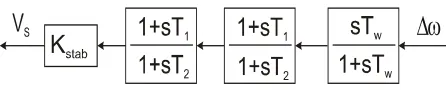
Fig. 6 Transfer Function Block Diagram of Delta-Omega Power System Stabilizer
To understand the effect of loading condition on synchronizing torque and damping torque considering
AVR, a typical value of KA=50 is substituted in equations 2
and 3. Figs. 4 and 5 show the variation in synchronizing
torque (Ks) and damping torque (Kd) when active power is
increased from 0.2 to 1.2 p.u. Fig. 5 clearly indicates that AVR reduces damping torque significantly for nominal and high loading conditions and provides more negative damping for weak systems whereas small positive change is observed in synchronizing torque. Negative damping of oscillation is not acceptable in the systems. These facts are also corroborated by dynamic responses of the system (Figs. 7 and 8) considering 5% step change in mechanical torque at t = 1sec. System becomes unstable in presence of AVR.
V. DYNAMIC MODEL OF THE SYSTEM WITH DAMPING
CONTROLLER IN SATE SPACE FORM
The transfer function block diagram of Delta-Omega power system stabilizer is shown in Fig.6. The state space model of the system with Delta-Omega type damping controller is written as:
p
x
x
. (4)Where, state vector is
fdv
1v
2v
s
x
Vs is a control signal obtained from the damping controller.
Perturbation vector ref m V T p 0 0 0 T K 0 0 T T H 2 K H 2 K 0 0 0 H 2 1 0 d A 2 1 stab stab 2 w 1 2 2 1 stab 2 2 1 stab 1 2 1 stab w stab 2 stab 1 stab R R 6 R 5 0 d A 0 d A 0 d 3 0 d 4 0 2 1 T 1 T T 1 T 1 0 T T H 2 K K T T H 2 K K T T H 2 DK 0 T 1 0 H 2 K K H 2 K K H 2 DK 0 0 T 1 T K T K 0 T K 0 T K T K 1 T K 0 0 0 0 0 0 0 0 0 H 2 K H 2 K H 2 D A
VI. DESIGN APPROACH FOR THE DELTA-OMEGA PSS
a) A hybrid optimization approach based on phase compensation and ISE techniques are used for designing the Lead – lag network and stabilizing gain setting respectively.
A. Text Design of Lead-Lag Network Using Phase Compensation Techniques
Following steps are involved in this design procedure:
b) Step1. Computation of natural frequency of oscillation
n from the mechanical loop.Neglecting the effect of damping D, the characteristic equation of the mechanical loop is written as:
Ms
2
0K
1
0
(5)International Journal of Emerging Technology and Advanced Engineering
Website: www.ijetae.com (ISSN 2250-2459, ISO 9001:2008 Certified Journal, Volume 3, Issue 6, June 2013)
s
1,
s
2
j
K
1
0M
(6)Thus the natural frequency of Oscillation is:
n
K
1
0M
(7)Step 2. Computation of phase lag between stabilizing signal (
v
s) and field flux (
fd)The transfer function relating
v
s and
fd includingthe feedback effect of
K
6 and setting
0
(Fig. 1) is:
3 63 3
1 sT K K K
K K s
GEP
A A
….. (8)
Let
be the phase angle of GEP(s) i.e. phase lag
n
j s
s
GEP
….. (9)Thus
6 3 3 1
1 tan
K K K
T
A n
Step3. Deign of Washout block of Delta-Omega PSS (Fig.6)
T
w is taken as 10 for the reasons mentioned in earliersection
So
n
j s w w w
sT
sT
G
1
(10)Let the lead introduced by this block be ‗
‘ so
tan
1
nT
w
2
(11)Step4. Design of Phase lead compensator Gc
The phase lead compensator Gc is designed to provide required degree of phase compensation
For 100% phase compensation,
G
c
j
n
GEP
j
n
0
(12)If the phase lead requirement exceeds 45 degrees, two identical cascade connected lead blocks are used, the
transfer function of the phase compensator Gc of the PSS
becomes.
2
1
1
1
sT
sT
s
G
c
(13)T2 is assumed to be 0.05 from realization point of view.
T1 is so calculated that the phase lead so obtained is equal
to phase lag introduced by GEP. Accounting for the phase
lead introduced by the washout filter, T1 is calculated by
1
1
tan
1
2
2
tan
nT
nT
(14)Here two identical lead –lag networks are assumed.
B. Computation of Optimum Gain (Kstab) using ISE Technique fo PSS
The optimum value of gain setting (Kstab) is obtained
using integral of squared errors (ISE) technique. The choice of a suitable performance index is extremely important for
applying ISE technique for the optimization of Kstab of PSS.
In order to obtain optimum Kstab, a quadratic performance
index J as given below is evaluated for several values of
Kstab considering a step perturbation in mechanical torque.
The optimum gain setting is the one that results in minimum value of J.
0
2
dt
)
t
(
International Journal of Emerging Technology and Advanced Engineering
Website: www.ijetae.com (ISSN 2250-2459, ISO 9001:2008 Certified Journal, Volume 3, Issue 6, June 2013)
For T1* = 0.2825 sec., as computed using equation-14 at
nominal loading condition, J first decreases with increase in
Kstab, attains a minimum value (Jmin) for Kstab=27.48, and
then increases with further increase in Kstab. Hence, Kstab=
27.48 becomes optimum gain setting of the PSS. Thus the optimum parameters of the Delta-omega PSS obtained using hybrid optimization technique are as follows:
Kstab* = 27.48, T1* = 0.2825 sec., T2 = 0.05 sec.
The above PSS parameters are obtained for KA = 50.00.
VII. DYNAMIC PERFORMANCE OF THE SYSTEM WITH
DELTA-OMEGA PSS
The nominal parameters of the system considered for the design are given in the appendix-1. The parameters of
PSS to be optimized are Kstab, Tw, T1 and T2. Based on the
hybrid optimization, as explained in previous section, the
time constant T1, T2 and Kstab are calculated equal to 0.2825
sec., 0.05 sec. and 27.4794 respectively. The model parameters, design data and PSS parameters are given in Table-1.
TABLEI
MODEL AND DESIGN PARAMETERS
Model and Design Parameters Corresponding to Pe=0.9, Qe=0.2907, Vt=1.0, Xe=0.65
K1 0.7689 K5 - 0.1461 T2 0.05
K2 0.8701 K6 0.4151 Tw 10.0
K3 0.3237 Ksta b
27.4794 T1 0.2825
K4 1.4274 T3 2.3613
Natural frequency of oscillation (Electromechanical mode)
1.011 Hz
Phase Lag introduced / Phase Lead required
32.518 degree
Phase Lead Provided by
Wash-out block 0.7807 degree
Lead Compensator 31.7374 degree
TABLE2
MODEL AND DESIGN PARAMETERS
Eigen Values, frequency and Damping Ratio of the System Parameter Corresponding to Pe=0.9, Qe=0.2907, Vt=1.0,
Xe=0.65
Eigen Values Frequency Hz
Damping Ratio
Without AVR
-0.1596 ± j6.3785
-0.2.22 1.0155 0.0251
With AVR only
0.43449 ± j6.3383,
-1.29,
-4.24
-14.26
-51.78
1.011 -0.0684
With PSS
Kstab = 27.4794
T1 = 0.2825
T2 = 0.065
-1.6694 ± j3.1
-4.33 ± j20.5
-0.14 , -50.60
-1.36
-4.11
-14.59
0.5601
3.3888
0.47
0.2
The dynamic response of the system for
and
for the nominal operating condition, with and without PSS, following 5% step increase in mechanical torque, were obtained [Figs. 7 and 8]. It is observed that the system behaves satisfactorily with damping controller as the responses settle to their steady state values in less than 2.5 second whereas the system is unstable without damping controller.
International Journal of Emerging Technology and Advanced Engineering
Website: www.ijetae.com (ISSN 2250-2459, ISO 9001:2008 Certified Journal, Volume 3, Issue 6, June 2013)
Fig. 7 : Dynamic responses of the system for
considering 5%disturbance in mechanical torque (
T
m= 0.05 p.u.) at 1 sec. withoptimum Delta-Omega PSS.
Fig. 8 : Dynamic responses of the system for
considering 5%disturbance in mechanical torque (
T
m= 0.05 p.u.) at 1 sec. withoptimum Delta-Omega PSS.
[image:7.612.330.549.147.327.2]Eigen values, frequency and damping ratio of oscillatory mode, when AVR is not considered, are also shown in Table 2 for comparative studies. It clearly indicates that system is stable and oscillatory mode was poorly damped. When AVR is used, the damping ratio becomes negative. Hence optimum PSS is required for increasing damping torque. Damping ratio is increased from –0.0684 to 0.4743 by introducing optimum damping controller (PSS).
Fig. 9 : Dynamic responses of the system for
considering 5%disturbance in mechanical torque (
T
m= 0.05 p.u.) at 1 sec.with optimum Delta-Omega PSS.
Fig. 10 : Dynamic responses of the system for
considering5% disturbance in mechanical torque (
T
m= 0.05 p.u.) at 1sec. with optimum Delta-Omega PSS.
This fact is also corroborated from dynamic responses
for
and
of the system obtained with and without [image:7.612.58.280.147.316.2] [image:7.612.53.276.386.552.2] [image:7.612.344.555.422.588.2]International Journal of Emerging Technology and Advanced Engineering
Website: www.ijetae.com (ISSN 2250-2459, ISO 9001:2008 Certified Journal, Volume 3, Issue 6, June 2013)
Studies are further extended to understand the effectiveness of designed PSS in the system with AVR.
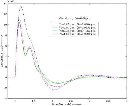
The dynamic responses of the system for
and
wereobtained (Figs. 9 and 10) considering 5% disturbance in mechanical torque at time 1 sec., for following operating conditions:
1. Pe = 1.00 p.u., Qe = 0.3698 p.u.,
2. Pe = 0.75 p.u., Qe = 0.1952 p.u.,
3. Pe = 0.50 p.u., Qe = 0.0835 p.u., and
4. Pe = 0.25 p.u., Qe = 0.0204 p.u.
Here Xe = 0.65 p.u. and Vt = 1.0 p.u. are considered.
Examination of the different responses, it is revealed that PSS provides the robust performance over a wide variation in loading condition.
VIII. CONCLUSION
The following are the significant contributions of the work presented in this paper.
1. A small perturbation state space modal of a system
comprising single machine, connected to an infinite bus through a transmission line has been developed.
2. Effect loading condition on synchronizing torque and
damping torque is studied in detail and it was inferred that damping torque becomes negative at higher loading conditions.
3. New hybrid optimization technique based on phase
compensation and ISE techniques for optimizing the parameters of the Delta-Omega PSS has been presented.
4. A detailed analysis reveals that the system responses
are satisfactory by introducing an appropriately designed delta-Omega PSS and power oscillations damped out within 2.5 seconds.
Studies further indicate that designed Delta-Omega PSS provides the robust performance over wide variation in loading condition.
IX. REFERENCES
[1] M.K.Bhaskar, ―Design of Radial Basis Function network based Dual input power system stabilizers.‖ M.E Dissertation, Department of Electrical Engineering, J.N.V. University, Jodhpur, 2002.
[2] E. V. Larsen and D. A. Swann, ―Applying power
system stabilizers PartII: Performance objectives
and tuning concepts‖, IEEE Transactions on Power
Apparatus and Systems, Vol.PAS100, No.6, June
1981, pp.30253033.
[3] E. V. Larsen and D. A. Swann, ―Applying power
system stabilizers PartIII: Practical considerations‖,
IEEE Transactions on Power Apparatus and Systems,
Vol.PAS100, No.6, June 1981, pp.30343046.
[4] P. M. Anderson and A. A. Fouad, ―Power System Control and Stability‖, The Iowa State University Press, AMES, IOWA, USA, Vol. 1, U.S.A. 1984.
[5] IEEE committee report, ―Computer models for representation of digital based excitation systems‖, IEEE Transactions on Energy Conversion, Vol. 11,
No. 3, September 1996, pp.607615.
[6] Avdhesh Sharma, ‖Artificial Neural Network and Fuzzy Logic System based Dual Input Power System Stabilizers‖, Ph.D. Thesis, Electrical
Engineering Department, Indian Institute of
Technology, Delhi, (INDIA), 2001.
[7] E. V. Larsen and D. A. Swann, ―Applying power
system stabilizers PartI: General concepts‖, IEEE
Transactions on Power Apparatus and Systems,
Vol.PAS100, No.6, June 1981, pp.30173024
[8] P. Kundur, ―Power system stability and control‖, McGraw Hill, Inc., 1994.
[9] C. T. Tse and S. K. Tso, ―Design optimization of power system stabilizers based on modal and eigenvaluesensitivity analyses‖, Proceedings of IEE, Vol. 135, PartC, No.5, September 1988,
International Journal of Emerging Technology and Advanced Engineering
Website: www.ijetae.com (ISSN 2250-2459, ISO 9001:2008 Certified Journal, Volume 3, Issue 6, June 2013)
[10] D. P. Sengupta, ―Dynamic stability in electric power systems‖, Journal of the Institution of Engineers
(India), Vol. EL70, August 1989, pp.117124.
[11] M. A. Magdy and F. Coowar, ―Frequency domain analysis of power system forced oscillations‖, Proceedings of IEE, Vol. 137, No. 4, PartC, July
1990, pp.261268.
X. APPENDIX
The nominal system parameters and operating condition are:
H =3.5 sec, Tdo=8 sec,Xd=1.81 p.u.,Xd=0.3
p.u.,Xq=1.76 p.u. KA=400, TR=0.02 sec.,TA=0.05 sec.,TB
=1.0 sec., TC = 8.0 sec.
Pe =0.9 p.u., Qe=0.3 p.u., Vt=1.0078 p.u., Xe = 0.65
![Fig. 2 : Graph of Synchronizing torque ( Kd ) Vs Active power (Pe ) for various values of line reactance ( Xe ) [Without AVR]](https://thumb-us.123doks.com/thumbv2/123dok_us/8729215.886285/3.612.54.287.182.453/graph-synchronizing-torque-active-power-various-values-reactance.webp)