© 2017, IRJET | Impact Factor value: 6.171 | ISO 9001:2008 Certified Journal
| Page 1191
ENHANCED MULTI – AGENT BASED INDUSTRIAL PROCESS
AUTOMATION
Ihedioha Ahmed C.
1, Eneh Ifeanyichukwu I.
21,2
Enugu State University of Science and Technology Enugu, Nigeria
---***---Abstract -
The current day-to-day problem faced bythermal power plants is the requirement of economic and reliable operation towards achieving maximum efficiency. An effective way to realize this objective is to make improvements in the existing controls with the modem techniques. Regulation of air and fuel to optimize combustion for meeting varying load is an important parameter in boiler operation. A multi agent control system (MACS) for a fossil-fuel power unit is presented. Every agent in the MACS is an intelligent agent making decision according to the operating condition of the power plant. This agent uses Neuro-Fuzzy to evaluate the produced optimized gains for feedback control. To show that the Gain Optimizer agent can produce improved gains when needed, a simulation was run in which the MAS a was used to control the system, but the Feedback agent were intentionally initialized with gains that would cause the power plant model output to exceed one or more of the thresholds that trigger a gain optimization. The result shows that these agents can be successfully implemented simultaneously in MAS to achieve the coordinated goal of customizable optimized multiobjective power plant control.
Key Words: Multiagent Control System (MACS),
Neuro-Fuzzy, Gain Optimizer, Thermal power plants.1. INTRODUCTION
The problem facing Nigeria electric power industry today can be attributed to society’s ever increasing demand for energy, environmental concerns with reliance on fossil fuels, and uncertainty about an aging infrastructure’s ability to cope with increasing demand for energy. Existing control systems for power plants are rigid and lack the capability to provide optimal operation with increasing amounts of requirements placed on the power plants, prompting the need for a more adaptive, robust control system.
This research presents an enhanced multi – agent based industrial process automation based on the concept of Multi-Agent Systems (MASs), which have been applied to other complex problems in the power industry. It applies a MAS distributed control methodology to a large-scale power plant optimized control system, improving the overall flexibility, autonomy, and robustness of the control system using Neuro-Fuzzy technology, which in turn increases the efficiency and operation of the power plant.
A methodology for MAS design was formulated by merging concepts from the fields of software engineering, control engineering, and concepts from intelligent systems theory and intelligent machines in [1]. The resultant control
system structure, seen as an open organization of
intelligent agents, constitutes a general framework for the development of large-scale intelligent control system.
2.0 REVIEW OF RELATED LITERATURE
Authors in [2] developed a dynamic mathematical model of a three-boiler steam generation process and control structure to improve dynamic robustness. The main objective is to prevent cascaded tripping of boiler. A trip of one boiler causes a drop in steam header pressure, which produces “boiler swell” in the untripped boilers. These effects will shut down all the untripped boilers through drum level high protection. The variables that affect the boiler swell are the rate of fuel firing to the boiler and the rate of feed water flow to the drum. The dynamic model developed by them contains ordinary differential equations describing mass and energy balances for each of the three boilers and a mass balance of the steam header. The model was tested with override control scheme to prevent cascaded tripping. In this design, coordinated control scheme has not been dealt which will control the header pressure as per boiler capability curve including feed water flow to the boiler. Also he has not included the combustion process in his model.
Authors in [3] presented a non-linear dynamic model for natural circulation type drum boilers. The model describes the dynamics of the drum, down comers and riser components derived from first principle and are characterized from physical parameters. In this model the shrinks and swells phenomena associated with the drum water level have been given more importance than combustion control system.
© 2017, IRJET | Impact Factor value: 6.171 | ISO 9001:2008 Certified Journal
| Page 1192
Authors in [5] presented a nonlinear control orientedboiler modeling by modifying the boiler model developed in [6]. A nonlinear combustion equation with a first-order lag was introduced for excess oxygen in the stack and the stoichiometric air to fuel ratio for complete combustion. The air fuel ratio is one of the uncertain parameters to develop the oxygen level equation. They showed that the air to fuel ratio in the model varied linearly with oxygen level. But in practical case only the air and fuel flow are directly proportional to steam flow demand. But the oxygen level is more at low loads and less at higher loads, which is not linear.
Authors in [7] developed dynamic simulation model for drum type boiler with turbine bypass system and its application in the study and the design of a new control philosophy. The thermo dynamic parameters for the numerical model are set at one equilibrium condition and the physical parameters represent all the storage terms (masses and volumes) to replicate the dynamics of the physical units. The physical and performance data for the plant model was obtained from the data information sheets, design data and heat balance diagrams which was provided by the manufacturers. Practically the data from heat balance diagrams will not match the real time values. Authors in [8] developed dynamic model to design an improved control strategy for pulverized coal fired drum type boiler. The control techniques to improve load cycling capabilities were discussed with respect to firing rate, steam pressure, steam temperature, excess air and exhaust air temperature. The control system described is conventional in nature and does not incorporate or involve the use of any advanced control concepts.
Authors in [9] developed section wise mathematical model for reheat boiler-turbine-generator and simulated using the physical parameters obtained from steam table and unit acceptance test. In this much important has not been given for furnace dynamics with respect to control parameters.
Authors in [10] developed a power plant model for operator training simulators. In this model the coordinated control was much simplified. The governor dead band was ignored. Valve functions were assumed to be linear.
In the last three decades, there has been significant research work on boiler modeling and control. The model architectures described in the literatures are capable to capture static relationship between input and output data. However control applications require dynamic process models. Dynamics of the furnace is not adequately presented and hence these models have less practical significance. The use of models to solve the complex and interactive control problem of boiler systems have not been seen any significant extent. Lack of good nonlinear, control-oriented model for boiler is a bottleneck for using
model-based controllers to obtain input-output behavior for the process. The complexity involved in obtaining the reasonably accurate model is high. If assumptions were made to reduce complexity in obtaining models, it would yield degraded performance of controllers. Because of high nonlinearity and uncertainty of the boiler system, it is very difficult to achieve exact control oriented mathematical model particularly for combustion process and also it is less reported in the literature.
2.1 Power Generation in Nigeria
Power generation in Nigeria dates back to 1886 when two (2) generating sets were installed to serve the then Colony of Lagos. By an Act of Parliament in 1951, the Electricity Corporation of Nigeria (ECN) was established , and in 1962, the Niger Dams Authority (NDA) was also established for the development of hydroelectric power. A merger of the two (2) organizations in 1972 resulted the formation of the National Electric Power Authority (NEPA) which was saddled with the responsibility of generating, transmitting and distributing electricity for the whole country. In 2005, as a result of the power sector reform process, NEPA was unbundled and renamed Power Holding Company of Nigeria (PHCN). The Electric Power Sector Reform (EPSR) Act was signed into law in March 2005, enabling private companies to participate in electricity generation, transmission, and distribution. The government unbundled PHCN into eleven electricity distribution companies (DisCos), six generating companies (GenCos), and a transmission company (TCN). The Act also created the Nigerian Electricity Regulatory Commission (NERC) as an independent regulator for the sector. At present, the Federal Government has fully divested its interest in the six GenCos while 60% of its shares in the eleven (11) DisCos have been sold to the private operators. The Transmission Company still remains under government ownership.
The generation sub-sector presently includes 23 grid-connected generating plants in operation with a total installed capacity of 10,396 MW (available capacity of 6,056 MW) with thermal based generation having an installed capacity of 8,457.6MW (available capacity of 4,996 MW) and hydropower having 1,938.4 MW of total installed capacity with an available capacity of 1,060 MW. This comprises of the privatized GenCos, Independent Power Producers (IPPs) and the generating stations under the National Integrated Power Project (NIPP).
IPPs are power plants managed by the private sector prior to the privatization process. These include Shell operated – Afam VI (642MW), Agip operated – Okpai (480MW), Ibom Power, NESCO and AES Barges (270MW).
© 2017, IRJET | Impact Factor value: 6.171 | ISO 9001:2008 Certified Journal
| Page 1193
funded emergency intervention scheme. The company hasa mandate to manage the National Integrated Power Projects (NIPP) which essentially involves the construction of identified critical infrastructure in the generation, transmission, distribution and natural gas supply sub-sectors of the electric power value chain.
In the generation sub-sector, NDPHC is expected to add ten (10) new gases fired power stations to the grid some of which have already been completed and commissioned, while others are at different stages of construction in different parts of the country.
3.0 LARGE-SCALE FOSSIL FUEL POWER PLANT
DESCRIPTION
The large-scale power plant under consideration in this thesis is a 600MW oil fired drum-type boiler-generator fossil-fuel electrical power plant unit (FFEPU).
The steam generating unit is an oil-fired, balanced draft, controlled recirculation drum boiler which can deliver up to 4.2 x 10⁶ (lbs.)/hr of steam at a pressure of 2600 psig and 1005°Fand reheat from 625°F to 1000°F. The boiler unit also has six recirculation pumps that supply the required recirculation flow with only four of these needed to supply sufficient flow for full load operation for the FFEPU. To address air flow, two forced-draft fans permit the primary air and two induced-draft fans are set to maintain the furnace pressure at a desired pre-set point [11].
Furthermore, in the boiler system two condensate pumps and a combination of combined booster and main boiler feed pumps address the feedwater flow.
The turbine system is a tandem compound triple pressure steam turbine. The system is composed of a high-pressure, intermediate pressure and two double flow low pressure turbines rotating on a common shaft at a rated speed of 3600 rpm, or 60Hz, and exhausting pressure at 2 in. Hq absolute. At maximum load, the throttle steam is designed to meet conditions of 2400 psig and 1000°F, and reheat steam at 1000°F. The turbine system is coupled directly to the generator unit, which is capable of producing 685,600kVa, 3-phase, 60Hz, at 22kV at a power factor of 0.90 [11].
3.1 System Description and Characteristics
The FFEPU model represents accurately the boiler-turbine unit and needs to provide not only a physical realistic model of the mechanical power systems but must also incorporate interactions between the mechanical and electrical component of the power plant. This FFEPU model in [12] is an improvement to previous models [13] for two very important aspects. Previously, the condensate
dynamics and the feedwater dynamics had not been considered nor modeled due to the assumption that they do not have a considerable effect, but these dynamics are explicitly modeled in [12]. Secondly, this model actually accounts for the electrical fans and pumps and how their dependence on voltage and frequency affect the overall system. Other important features that characterize this FFEPU model are:
- The model development is based upon physical processes with model parameters determined from geometry, material properties and manufacturer’s data.
- Nonlinearities usually overlooked to obtain simpler models are included to allow the model to be valid over a wide operating range.
- In order to provide physically realistic thermodynamic properties, steam table property fits are used.
- It is possible to verify the power plant model since an actual operating power plant was used as prototype and data can be compared.
Therefore this FFEPU model presents characteristics that are desirable for implementation of the proposed control configuration.
3.3 Power Plant Modules and Subsystems
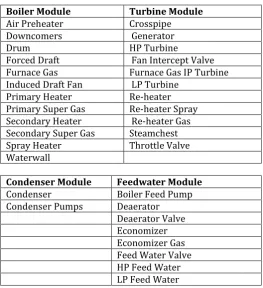
The FFEPU model has been implemented and simulated in MATLAB previously [14]. The FFEPU is a twenty-third order nonlinear dynamic model and it is divided in four different modules, which are the boiler module, the turbine-generator module, the condenser module and the feedwater module. Each of these modules is also composed of a total of thirty three subsystems. Twelve of these subsystems model the boiler module, eleven make the turbine module, two make up the condenser module and eight make up the feedwater module. This distribution is better represented in Table 1. Many of the modules are interconnected and also many of the subsystems are connected to each other.
© 2017, IRJET | Impact Factor value: 6.171 | ISO 9001:2008 Certified Journal
| Page 1194
Table 1: FFEPU Modules and Subsystems.Boiler Module Turbine Module
Air Preheater Crosspipe
Downcomers Generator
Drum HP Turbine
Forced Draft Fan Intercept Valve
Furnace Gas Furnace Gas IP Turbine
Induced Draft Fan LP Turbine
Primary Heater Re-heater
Primary Super Gas Re-heater Spray
Secondary Heater Re-heater Gas
Secondary Super Gas Steamchest
Spray Heater Throttle Valve
Waterwall
Condenser Module Feedwater Module
Condenser Boiler Feed Pump
Condenser Pumps Deaerator
[image:4.595.30.294.106.395.2]Deaerator Valve Economizer Economizer Gas Feed Water Valve HP Feed Water LP Feed Water
Table 2: FFEPU Control Valves in each Module.
Boiler Module Turbine Module
u1: Fuel Flow u8: Governor Control Valve
u2: Gas Recirculation u9: Intercept Valve
u3: Induced Draft Fan u4: Forced Draft Fan u5: Combustor Gun Tilt u6: Super-heater Spray Flow
u7: Re-heater Spray Flow
Condenser Module Feedwater Module
u10: Deaerator Valve u11: Feed-water Valve
u12: Feed Pump turbine Flow
3.4 Control pattern
Typical control methodologies for FFEPUs that take a centralized approach or loosely decentralized approach cannot manage the enormous complexities of a large-scale power plant and at the same time provide the power plant with optimal operation. FFEPUs under these control methodologies can be susceptible to entire failure when one individual system fails [15]. Recently, there has been interest in Multi-Agent System (MAS) applications in the area of Power Engineering. With a MAS control methodology, the system can be built to be flexible, robust, and extensible [16]. A MAS is a system that consists of two
or more intelligent agents. Each intelligent agent in the system is responsible for his or her own individual task, and with the collective completion of other agents’ individual tasks, the overall goal of the system can be reached. Thus one of the most important properties of MAS is that no one intelligent agent knows the overall goal of the system. With these properties, a FFEPU under MAS control can better adapt to changing objectives and additional requirements placed upon its operation. The intelligent agents in the system work together to reduce coupling between many of the distributed systems in the FFEPU, and thereby the FFEPU is better able to handle the complexities of its many distributed systems. In this research, a MAS control methodology is applied to a 600 MW FFEPU to make it more adaptive and responsive.
i. Coordinator Agent
The goal of the coordinator agent is to coordinate the agents in the MACS according to different operating conditions.
The coordinator agent COA is an important agent in the MACS. It perceives the environment of the MACS to make system level decision. It gets different information from every agent in the MACS and even from the operator. It analyzes and decides what kind of message should be sent to which agent.
Firstly, the COA checks the unit load demand and the operation command from the operator. Then the COA checks the state of the MACS according to the output of the FFPUA.
If the unit load demand changes large and rapidly, the COA will decide to ask the reference agent RA to generate optimal set-points and asks the FFCAs to generate feedforward control signals. At the same time, if the error between the setpoints and the output of the FFPUA is found big, the COA will ask the FBCAs to work to eliminate the error as soon as possible. Otherwise, if the unit load demand does not change, the COA will decide not to ask the RA and the FFCAs to work.
ii. Communication between Agents
Every agent is an intelligent and flexible entity with goals, actions, and domain knowledge. They collaborate each other through communication to achieve a global goal that is beyond the ability of each individual agent.
© 2017, IRJET | Impact Factor value: 6.171 | ISO 9001:2008 Certified Journal
| Page 1195
Fig. 1: The communication between the agents in theMACS
As shown in Fig. 1, the COA communicates with every agent by passing messages. There are two kinds of messages: data and text in the MACS. For the text message, the COA sends run or stop command to the RA, FBCAs and FFCAs, and they in turn reply yes or no to the COA.
As for the data message, the RA sends the set-points E, P, L to the COA, the FBCAs send the feedback control signals to the COA. The FFPUA will send output E, P, L to the COA when asked.
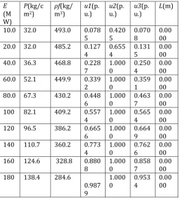
3.5 OPERATING WINDOW DATA
The two tables below contain the data needed to construct the power-pressure and power input operating windows for the 160 MW power plant used in this research.
Table 3(a) Upper pressures limit data.
E (M W)
P(kg/ cm2)
ρf(kg /m3)
u1(p.u.
) u2(p.u.) u3(p.u.) L(m)
10.0 237.4 318.1 0.322
5 0.2102 0.1226 0.0000
20.0 231.8 312.0 0.361
0 0.2362 0.1683 0.0000
40.0 220.9 300.8 0.438
5 0.2965 0.2607 0.0000
60.0 210.2 290.1 0.516
7 0.3551 0.3544 0.0000
80.0 199.7 278.9 0.595
6 0.4251 0.4495 0.0000
100 189.5 268.1 0.675
2 0.5032 0.5459 0.0000
120 179.5 257.8 0.755
5 0.5907 0.6439 0.0000
140 169.7 247.1 0.836
6 0.6890 0.7434 0.0000
160 160.2 236.8 0.918
3 0.7996 0.7996 0.0000
180 150.9 226.3 1.000 0.924
5 0.9245 0.0000
Table 3.(b) Lower pressure limit data.
E (M W)
P(kg/c m2)
ρf(kg/ m3)
u1(p.
u.) u2(p.u.) u3(p.u.) L(m)
10.0 32.0 493.0 0.078
5 0.4205 0.0708 0.0000
20.0 32.0 485.2 0.127
4 0.6554 0.1315 0.0000
40.0 36.3 468.8 0.228
7 1.0000 0.2504 0.0000
60.0 52.1 449.9 0.339
2 1.0000 0.3591 0.0000
80.0 67.3 430.2 0.448
6 1.0000 0.4637 0.0000
100 82.1 409.2 0.557
4 1.0000 0.5654 0.0000
120 96.5 386.2 0.665
6 1.0000 0.6649 0.0000
140 110.7 360.2 0.773
4 1.0000 0.7626 0.0000
160 124.6 328.8 0.880
8 1.0000 0.8587 0.0000
180 138.4 284.6
0.987 9
1.000
0 0.9534 0.0000
[image:5.595.64.266.87.221.2]4.0 RESULTS
[image:5.595.304.566.109.399.2]Fig. 2 shows a unit load demand that resembles a typical load cycle.
Fig.2: Unit load demand.
[image:5.595.311.545.478.610.2] [image:5.595.30.328.495.792.2]© 2017, IRJET | Impact Factor value: 6.171 | ISO 9001:2008 Certified Journal
| Page 1196
Fig. 3 shows the solution space for the given unit load [image:6.595.44.271.130.253.2]demand.
Fig. 3: Solution space by the given unit load demand.
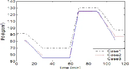
The gaps between upper and lower limits are the solution space for the optimization process. This is because the solution space for the feedwater valve is very small as shown in Fig. 3. All simulation results are improved as the number of objectives is increased. The demand pressure
set-points, mapped for different number of objective
functions are shown in Fig. 4. This is because the power pressure operating window is quite large and the same amount of power can be produced on a wide range of pressure. As additional objective functions are added in the optimization, the plant is operating more conservatively in lower pressure.
Fig. 4: Demand pressure set-point trajectories.
5
.
CONCLUSION
The goal of this research was to design, implement, and test a multi-agent system (MAS) intended for decentralized optimized multi-objective control of a fossil fuel power unit (FFPU). This control methodology is intended to provide optimized control of an FFPU while allowing the customization of operating goals as needed to conform to changing market situations, such as changing regulations, the cost of fuel, and load demands on the unit. To do this, a MAS was developed consisting of agents that have been designed to perform specific tasks, which in coordination, achieve the desired control. This MAS was designed for a smaller, simpler FFPU model in order to
focus on developing the MAS without the added difficulty of accounting for the complexity of a larger power plant model. In conclusion, this research shows that MAS can be used to implement a control system intended for a FFPU. This thesis also shows that agents can be used to implement each of the control techniques discussed here. Furthermore, this research shows that these agents can be successfully implemented simultaneously in MAS to achieve the coordinated goal of customizable optimized multi objective power plant control of an FFPU.
REFERENCES
[1] Oseni M. O (2012). Improving households’ access to electricity and energy consumption pattern in Nigeria: renewable energy alternative. Renew Sustain Energy Rev 2012;16:3967–74.
[2] Padgham L. and M. Winikoff, (2004). Developing Intelligent Agent Systems, John Wiley & Sons, 2004.
[3] Oswald N., and Levi P., (1997) “Cooperative vision in a multi-agent architecture. Image analysis and processing lecture notes in computer science”. Volume 1310, pp 709-716, 1997.
[4] Monch L., and Stehli M.,(2006) "ManufAg: a multi-agent-system framework for production control of complex manufacturing systems," Information Systems and E-Business Management, vol. 4, no. 2, pp. 159-185, April 2006.
[5] Moreau L. (2002) “Agents for the grid: a comparison for Web services (Part 1: the transport layer)”. In Second IEEE/ACM International Symposium on Cluster Computing and the Grid (CCGRID 2002) (eds. Bal HE, Lohr KP and Reinefeld A), pp. 220-228. IEEE Computer Society, Berlin, Germany.
[6] Heo J. S. and K. Y. Lee and R. Garduno-Ramirez,( 2005) “Multiobjective optimal power plant operation using particle swarm optimization technique,” in Proc. IFAC Congress, Prague, 2005, paper code: 04833.pdf, Tu-M06-TO/4.
[7] McDonald J. P., H. G. Kwatny, and J. H. Spare,(1971) “A Non-Linear Model for Reheat Boiler-Turbine Generator Systems: Part I – General Description and Evaluation,” in Proc. 12th Joint Automatic Control Conf., pp. 219-226, 1971.
[image:6.595.49.262.449.562.2]© 2017, IRJET | Impact Factor value: 6.171 | ISO 9001:2008 Certified Journal
| Page 1197
[9] Jennings N. and Wooldridge M. (1998b) “Applicationsof intelligent agents”. In Agent Technology: Foundations, Applications, and Markets (eds. Jennings NR and Wooldridge MJ), Chapter 1, pp. 3-28. Springer.
[10] McArthur, S. D. J. McArthur, E. M. Davidson, V. M. Catterson, A. L. Dimeas, N. D. Hatziargyriou, F. Ponci and T. Funabashi, (2007 ). “Multi-Agent Systems for Power Engineering Applications – Part I: Concepts, Approaches, and Technical Challenges,” IEEE Transactions on Power Systems, vol. 22, no. 4, Nov. 2007.
of power plant using particle swarm optimization techniques,” IEEE Trans. Energy Conversion, vol. 21, no.2, pp. 552-561, Jun. 2006.
[13] Heo J. S. and K. Y. Lee, (2006). “A Multi-Agent System-Based Intelligent Heuristic Optimal Control System for a Large-scale Power Plant,” IEEE
Congress on Evolutionary Computation,
Vancouver, BC, Canada, pp. 5693-5699, Jul. 2006.
[14] Jennings N.R (2001) “An agent-based approach for
building complex software systems”.
Communications of the ACM 44(4), 35-41.
[15] Fischer, T., Wood M. F., and Sparkman C. H (2001). “Multi-agent systems engineering” International journal of software engineering and knowledge engineering. Vol. 11, No. 3, 231-258. 2001.
[16] Fraile I., (2006) “Object-Oriented Systems Analysis and Design using UML”. 3rd edition. Berkshire:
McGrawHill, Pp 68-88, 2006.
[12] Heo J. S. and K. Y. Lee, (2006) “Multi objective control [11] Jussila Janne,(2006) "Agent-Based Approach to Supervisory Information Services in Process Automation," M.S. Thesis, Departmentof Automation and Systems Technology Helsinki
University of Technology, Helsinki, Espoo, Finland,