© 2017, IRJET | Impact Factor value: 5.181 | ISO 9001:2008 Certified Journal | Page 622
A STUDY ON APPLICATION OF PASSIVE CONTROL TECHNIQUES TO RC
BRIDGES THROUGH NON LINEAR DYNAMIC ANALYSIS
Mr Praveen J. V
1, Adarsh N Hegde
2, Mr Raveesh R M
31,2
Sri Siddhartha institute of technology agalkote, tumakuru – 572105,Karnataka, India
3Design Engineer, Sculpture consultancy Tumakuru – 572105,Karnataka, India
---***---Abstract - Present study focuses on the study of effect of TMD with optimum parameters (frequency ratio and mass ratio). In this study TMD is used to reduce the vibrations in RC bridges. A RC bridge with different span with and without TMDs has been considered for the analysis. 3D models and analysis has been done by using a FE package SAP2000 by using direct integration method. TMDs with different mass ratios 2%, 3% and 4% are considered. The models were used to represent bridges located in zone 5 of India. The systemic parameters studied are natural period, base shear, roof displacement, lateral displacement, storey drift and shear force, bending moment of column. Time history analysis has been considered out .the structures has been subjected to a set-off ground motion Buhl for the bridges with, without TMDs and the results are interpreted
Key Words: TMD; RC bridge; Natural period; Base shear;
Roof displacement; lateral displacement; Storey drift and shear force; bending moment of column
1. INTRODUCTION
In the transportation systems highway and railway bridges play a vital role. In the design of these bridges the vibrations caused by the passageway of vehicles have become an important contemplation. Particularly the interaction problem between the moving vehicles and the bridge structures has attracted much attention during the last few decades. This is due to the speedy increase in the proportion of high-speed vehicles and heavy vehicles in the highway and railway passage and the tendency to use high-performance materials and more slight sections for the bridges.
Communication between the vehicle-bridge is a complex vibrant occurrence, which is a non-linear problem dependent on many parameters? These parameters include the natural frequencies of vibration and type of bridge, vehicle kind, vehicle speed and traversing pathway, number of vehicles and their relative positions on the bridge, highway surface irregularities, the damping description of bridge and vehicle etc. The first recorded research into bridge vibration appears to be a report published in the 19th century (Willis, 1849), which discussed the reasons for fall down of the Chester
Railway Bridge. In the first half of the 20th century, investigation into bridge vibration were mainly concerned with developing analytical solutions for simple cases of moving force (Timoshenko 1922, Lowan 1935, Ayre et al
1950, Ayre and Jocobsen 1950) and moving mass (Jeffcott, 1929).
The model of moving force is the simplest model whereby researchers can capture the necessary active characteristics of a bridge under the action of a moving medium, even though the interaction Between the vehicle and bridge is mistreated. Where the inertia of the vehicle camion is regarded as little, a moving mass mode is often adopted as an alternative. Though the moving mass model suffers from its inability to consider the bouncy effect of the moving mass, which is important in the presence of road surface irregularities or for vehicles running at high speeds.
The high-speed digital computer invention few decades ago made it possible to analyses the interaction problem with more complicated bridge and vehicle models. Vibration of different types of bridges such as girder bridges, slab bridges, cable-stayed bridges and suspension bridges due to affecting vehicles and trains could be considered by using moving vehicle representation, in which a vehicle was modelled as a mass-spring-damper, single-axle or multi-axle dynamic system. Even though wide-ranging studies have been done in this field, high-performance analysis methods are still required for accurate forecast of dynamic response of these bridges under moving trains and vehicles.
Alternatively, Allow for the dynamic effects resulting from the passage of vehicles, plenty of design codes such as American Association of State Highway and Transportation Officials (AASHTO) Standard Specifications for Highway Bridges (1996) require that the inactive live loads be increased by an impact problem, which is defined as the ratio of the maximum dynamic retort to the maximum static retort of the bridge minus one. AASHTO Specifications (Standard 1996), the impact factor is specified as a function of span distance end to end only. It is certainly a simplification. It’s been reported that the force factors calculated according to these codes may not be traditional in many cases. There exists an urgent need to develop reasonable design formulae based on accurate calculation of the true behaviour of the entire bridge-vehicle structure.
© 2017, IRJET | Impact Factor value: 5.181 | ISO 9001:2008 Certified Journal | Page 623 bridge-vehicle system. This thesis therefore focuses on
development of effective methods for analysing the vibration of various types of bridges including girder bridges, railway bridges, slab bridges and cable-stayed bridges under the action of moving trains and vehicles. The analysis of vibration of suspension bridges is expelled from this thesis due to the limitation of study period.
1.1) Types of Bridges.
Truss Bridge
Rigid Frame Bridge.
Arch Bridge
Cable Stayed Bridges.
Suspension Bridges.
Cantilever Bridges.
Beam Bridges.
Movable Bridges.
Girder Bridges.
A girder bridge is most commonly built and utilized bridge in the earth. Basic design in the most simplify form can be compared to a project ranging from one side to the other across a watercourse. Modern girder steel bridges two most common shapes are box girders and plate-girders. Beam may be made of concrete or steel. Particularly in rural areas where they may be exposed to overtopping and deterioration utilize concrete box beams. The term "girder" is typically used to refer to a steel beam. In a beam or girder bridge, the beams themselves are the primary support for the deck and they are responsible for transferring the load down to the foundation.
1.2) Types of Dampers
Friction Damper.
PVD Damper.
Pall Friction Damper.
Metallic Dampers (submission)
Lead Injection Damper (LED)
Viscous Dampers
Mass Damper
Mass is placed on a pivot which acts as a roller. And it allows to mass with move as a lateral movement to the base. Springs and dampers are placed between anchor members and mass to the base and frame and they are placed virtual in “opposite phase” and sometimes are adjoining vertical.
And these anchor members transmits structural lateral force. Bidirectional transfer dampers are made as a spring-damper in two vertical directions. And they provide controlling the structure movement in two vertical structures. Seismic isolator is used to isolate the structures of strong ground motions during an earthquake. Unlike building which its isolation is often done on the foundation, this separation is applied between topside of structure and below side of that in bridges. This is due to a high inertia force of topside (including deck weight) also it will be easy to use.
The main objective in seismic isolation is to reduce base frequency of structure vibration and reaching it to a lower
value than frequencies which have main earthquake energy. In other word, seismic isolation increases structure vibration period and bridge and distances it from periods containing earthquake main energies. So, the input energy to base caused by earthquake is reduced with seismic isolation. Another advantage of seismic isolation is to provide a tool to waste energy. So, inputted energy to structure gets wasted in small points and by a controlled manner. Thus, destruction and damaging in particular and few concentrated points will be existing and it will be possible to replace these parts after the earthquake. In general, seismic isolation design leads to reduce the structures responses reduction which is in earthquake conditions.
1) Objective & Methodology
The aim of the study is to evaluate the seismic performance of a bridge with & without TMD.
To study the feasibility of extraction the fundamental bridge frequency from the dynamic response of a vehicle passing over bridge.
To study the impact of a speed of vehicle on the structural response of different components of bridges.
The box girder bridge which is selected for the study is assumed to be located in zone 5 of India, the factors as listed above could be modelled for the study using the finite element analysis the analysis is carried out in SAP2000V14. The dynamic analysis would be carried out to study the impact of speed of the vehicles on the structural response of the bridges. The study will be conducted in the form of parametric study so that the studies could result in design chart. The input values to be used in FEM program shall be selected from the literature review initially and then revised based on the values and refined further if possible by conducting theoretical model studies.
2.1) Proposed study.
The box girder is adopted as a design example for a study.
It is 100m long & 11m wide Box-girder with two lanes bridge of traffic.
Only a particular span of 30m between two piers is chosen for study.
The span is considered to be as simply supported & restraining effect of a slab is
not considered.
The systematic parameters like natural frequency, time period displacements are studied.
The vibrations of systematic parameters of Bridge with and without TMDs are
Considering Bhuj earthquake data.
© 2017, IRJET | Impact Factor value: 5.181 | ISO 9001:2008 Certified Journal | Page 624
2) Range of parameters considered for the study
Table 2.1 Parameters
[image:3.595.31.245.128.454.2]
Table 2.2 Material Properties
4) Present Study
In the present study 3 dimensional box girder bridge models of different span with fixed base, with and without tuned mass damper of different mass ratio subjected to acceleration vs. time history of Bhuj earthquake studied. The tuned mass damper is modeled with elastic spring properties. The variation of frequency, time period and structural responses like base shear, displacement, acceleration for time history data and different vehicle speed is presented
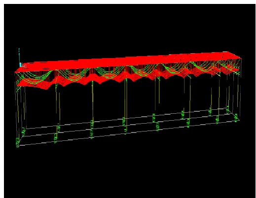
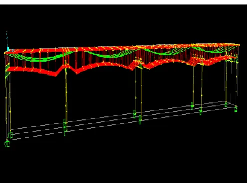
[image:3.595.308.564.245.460.2]The typical models layout plan considered in present study as shown in the figures 4.1 to 4.6 and input parameters are tabulated in table no 4.7 and 4.8
Fig 4.1: Shows the layout plan of 15m span Box Girder Bridge
Fig 4.2: Shows the front view of 15m span Box Girder Bridge
Type of bridge Box-girder bridge Total length of the
bridge
100m
Width of the bridge 11m Number of spans 7, 3, 3
Span distance 15m, 20m, 25m
Number of lanes 2
Number of tendons 5
Area of the tendon 6.452×E-04 Number of columns 2
Restraints fixed
Pier size 1m×1m
Bent cap size 1m×1m×9m
Lane width 5.5m
Type of vehicle Hsn-44(truck)
Vehicle speed Lane 1 50kmph,
Lane 1 75kmph, Lane 2 100kmph
Material properties Values
Unit volume 25KN/m3
Young’s modulus 32500×e6 KN/m2
Poisons ratio 0.15
Shear modulus 1.413×e10 N/m2
Co eff of thermal
expansion 1.17×e
-5/°C
Co eff of concrete 1.17×e-5 /°C
[image:3.595.45.247.496.702.2] [image:3.595.301.561.504.705.2]© 2017, IRJET | Impact Factor value: 5.181 | ISO 9001:2008 Certified Journal | Page 625
[image:4.595.38.288.321.505.2]Fig 4.3: Shows the layout plan of 20m span Box Girder Bridge
[image:4.595.37.287.552.724.2]Fig 4.4: Shows the front view of 20m span Box Girder Bridge
Fig 4.5: Shows the layout plan of 25m span Box Girder Bridge
Fig 4.6: Shows the front view of 25m span Box Girder Bridge
5) Result and Discussion
5.1) Variation in frequency
The variation of to Natural frequency due to the effect of tuned mass dampers is studied on box Girder Bridge with different span of 15m, 20m and 25m. The tuned mass dampers are modelled with different mass ratio (0.5%, 1%, 2%) and the result are tabulated as shown in the tables below.
5.1.1) Effect of mass ratio
In the discussion comparison is carried for the model with different mass ratio. It is observed that natural frequency increases with the increase in mass ratio and the percentage variation in frequency increases with increase in span length of the box girder bridge. The % variation for different mass ratio with different no of spans are tabulated in table 5.1 to 5.4
Table 5.1: Variation in frequency for 15m span
Mass Ratio
Span 15m
Frequency(rad/sec)
Without
TMD With TMD %Variation
0.5% 0.41182 0.35999 12.58%
1% 0.41182 0.30891 24.98%
[image:4.595.318.550.592.758.2]© 2017, IRJET | Impact Factor value: 5.181 | ISO 9001:2008 Certified Journal | Page 626
Graph 5.1: Variations in frequency in 15m
[image:5.595.38.287.86.240.2]From the above table and graph it is observed that there is a decrease in frequency of 12.58%, 24.98% and 41.23% after the implementation of tuned mass damper for the mass ratio 0.5, 1 and 2% of a 15m span box Girder Bridge respectively and maximum decrease in frequency is observed for 2% mass ratio when compared without TMD
Table 5.2: Variation in frequency for 20m span
Mass Ratio
Span 20m
Frequency(rad/sec)
Without
TMD With TMD %Variation
0.5% 0.11178 0.1021 8.6%
1% 0.11178 0.094895 15.10%
2% 0.11178 0.083717 25%
Graph 5.2: Variations in frequency in 20m
From the above table and graph it is observed that there is a decrease in frequency of 8.6%, 15.10% and 25% after the
[image:5.595.307.560.176.454.2]implementation of tuned mass damper for the mass ratio 0.5, 1 and 2% of a 20m span box Girder Bridge respectively and maximum decrease in frequency is observed for 2% mass ratio when compared without TMD
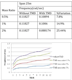
Table 5.3: Variation in frequency for 25m span
Mass Ratio
Span 25m
Frequency(rad/sec)
Without TMD With TMD %Variation
0.5% 0.11827 0.10894 7.8%
1% 0.11827 0.1006 14.9%
2% 0.11827 0.088174 25.44%
Graph 5.3: Variations in frequency in 25m
[image:5.595.309.559.592.751.2]From the above table and graph it is observed that there is a decrease in frequency of 7.8%, 14.9% and 25.44% after the implementation of tuned mass damper for the mass ratio 0.5, 1 and 2% of a 25m span box Girder Bridge respectively and maximum decrease in frequency is observed for 2% mass ratio when compared without TMD.
Table 5.4: Variation in frequency for 2% mass ratio
Span
2% mass ratio Frequency(rad/sec)
Without TMD With TMD %Variatio n
15m 0.41182 0.24201 41.23%
20m 0.11178 0.083717 25%
© 2017, IRJET | Impact Factor value: 5.181 | ISO 9001:2008 Certified Journal | Page 627
Graph 5.4: Frequency in different span with 2% mass ratio
From the above table and graph it is observed that there is a maximum decrease in frequency for 2% mass ratio after the implementation of tuned mass damper. For the mass ratio 2% of a 15, 20 and 25m span box Girder Bridge percentage variation of 41.23%, 25% and 25.44% respectively when compared without TMD
5.2) Variation in base shear
The variation of to base shear due to the effect of tuned mass dampers is studied on box Girder Bridge with different span of 15m, 20m and 25m. The tuned mass dampers are modelled with different mass ratio (0.5%, 1%, 2%) and the result are tabulated as shown in the graphs below.
5.2.1) Effect of ground motion
In the discussion comparison is carried for the model with different mass ratio. It is observed that base shear decreases with the increase in mass ratio. The base shear variation for different mass ratio in different no of spans is shown in the graph 5.5 to 5.7
Graph 5.5: Base shear due to ground motion in 15m span
From the above graph it is observed that there is a decrease in base shear after the implementation of tuned mass damper of mass ratio 0.5, 1 and 2% for a 15m span box Girder Bridge respectively and maximum decrease in base
shear is observed for 2% mass ratio when compared without TMD
Graph 5.6: Base shear due to ground motion in 20m span
From the above graph it is observed that there is a decrease in base shear after the implementation of tuned mass damper of mass ratio 0.5, 1 and 2% for a 20m span box Girder Bridge respectively and maximum decrease in base shear is observed for 2% mass ratio when compared without TMD.
Graph 5.7: Base shear due to ground motion in 25m span
From the above graph it is observed that there is a decrease in base shear after the implementation of tuned mass damper of mass ratio 0.5, 1 and 2% for a 25m span box Girder Bridge respectively and maximum decrease in base shear is observed for 2% mass ratio when compared without TMD.
Conclusion
Present study focused on the ability of TMD to reduce earthquake induced structural vibration. The frame is discretized using finite element technique (SAP2000). Numerical simulation has been performed to compare the box Girder bridge response by varying the span with the effect of variation of mass ratio of TMD.
From study it can be concluded that:
© 2017, IRJET | Impact Factor value: 5.181 | ISO 9001:2008 Certified Journal | Page 628 2. Time period increases with increases in the mass
ratio that is 2% and maximum variation is found in 15m span Box Girder Bridge.
3. Base reaction increases with increases in the mass ratio that is 2% and the maximum variation is found in 15m span Box Girder Bridge.
4. TMD has more potential to reduce Base Shear of structure when the mass ratio is 2% for a 15, 20 and 25m span Box Girder Bridge.
5. Joint Displacement of a structure increases with increase in span and after the implementation of TMD there is a substantial decrease in Joint Displacement maximum decrease is observed in case of mass ratio 2%.
6. Joint Acceleration of a structure increases with increase in span and after the implementation of TMD there is a substantial decrease in Joint Acceleration maximum decrease is observed in case of mass ratio 2%.
7. Joint Displacement of a structure increases with moving load and after the implementation of TMD there is a substantial decrease in Joint Displacement maximum decrease is observed in case of mass ratio 2%.
8. Joint Acceleration of a structure increases with moving load and after the implementation of TMD there is a substantial decrease in Joint Acceleration maximum decrease is observed in case of mass ratio 2%.
9. Is has been found that TMD with mass ratio 2% can successfully used to ontrol the vibration of the bridges.
References:
1) Resonance Characteristics Of Two-Span Continuous Beam Under Moving High Speed Trains Yingjie, Wanga, Qing Chao, Weia Jin Shia and Xuyou Long (2010)
2) Dynamic Response of Beam under Moving Mass. Mohan Charan Sethi (2012)
3) Vibration Analysis of Bridges under Moving Vehicles and Trains by Cheng Yuansheng (2000). 4) Dynamic Analysis Of A Railway Bridge Subjected To
High Speed Trains Dr. Raid Karoumi (2004) 5) Moving Load Analysis on Skewed Railway Bridge
Mehrdad Bisadi Shahrizan Baharom (2013). 6) Dynamic Response of Highway Bridges under a
Moving Truck and Development of Rational Serviceability Requirement Shabnam Darjani (2013).
7) Dynamic Analysis of Railway Bridges under High Speed Trains Ashish Gupta, Amandeep Singh Ahuja (2014).
8) Pedestrian excitation of bridges Department of Engineering, University of Cambridge (2004). 9) Random Vibration Analysis of Dynamic