http://dx.doi.org/10.4236/jpee.2015.34035
How to cite this paper: Peng, J.C., Zhou, J. and Jiang, H. (2015) A Liability Division Method for Harmonic Pollution Based on Line-Transferred Power Components. Journal of Power and Energy Engineering, 3, 262-268.
http://dx.doi.org/10.4236/jpee.2015.34035
A Liability Division Method for Harmonic
Pollution Based on Line-Transferred
Power Components
Jianchun Peng
*, Jun Zhou, Hui Jiang
College of Mechatronics and Control Engineering, Shenzhen University, Shenzhen, China Email: *[email protected]
Received February 2015
Abstract
The existing liability division methods for harmonic pollution are either inexplicit or incomplete in physical meaning. To compensate these defects, two new methods are proposed based on line-transferred power components in this paper. At first, all harmonic sources are represented by ideal equivalent current source, line current components and bus voltage components of a source are determined by stimulation of this source with all other sources disabled. Then, the line-trans- ferred power component owing to a source under all sources action together is determined by the theory of line-transferred power components, and called source’s line-transferred power compo-nent. At last, the liability of a source for line-end harmonic pollution is divided by two methods: the ration of the source’s line-transferred active power component to the total line-transferred power, and the ration of projection of the source’s line-transferred complex power component to absolute value of the total line-transferred complex power. These two methods are taken into ac-count not only harmonic voltage but also harmonic current in the liability division. Simulation re-sults show that the proposed liability division method based on active power component is the most effective and ideal one.
Keywords
Harmonic Pollution, Liability Division, Line-Transferred Power, Power Component, Grid
1. Introduction
With the development of modern industry and the use of a large number of power electronic devices, the har-monic sources have been increasing in power network. They seriously influence the normal work of sensitive loads and precision devices in the grid [1]-[4]. For the power quality pollution caused by harmonic waves, a management scheme of rewards and punishments is suggested in [5]. Therefore, a comprehensive, reasonable and quantitative liability division method of a source for harmonic pollution is crucial under the coexistence of several harmonic sources.
*
Considering the voltage sensitivity of electrical equipment, many researchers proposed a liability division method for harmonic pollution based on harmonic voltage. A non-invasive liability division method was pro-posed in [6] for harmonic pollution based on the fast components of harmonic current injected by harmonic sources and the statistical features of independent random vectors. A liability division method was proposed in [7] for assessing harmonic pollution based on the improvement of traditional least squares method and M-esti- mation robust regression. It overcomes the disadvantages of the traditional least squares method, such as the low accuracy, sensitivity to singular data. A liability division method was proposed in [8] for quantify the harmonic pollution, which is based on the estimated harmonic impedance and background harmonic voltage using com-plex least squares method. It overcomes the shortage of the linear regression method by using the real and im-aginary components respectively to estimate the harmonic impedance and quantify the harmonic liability.
There are some other researchers proposing a liability division method for harmonic pollution based on har-monic currents. A liability division method was proposed in [9] for harhar-monic pollution from the perspective of harmonic currents based on QR-RLS (Recursive Least-Squares Method based on QR decomposition). A liability division method was proposed in [10] for harmonic pollution, which apportions the voltage and current harmon-ic step by step considering the filter, initial phase angles of harmonharmon-ic voltage and current as well as the number of harmonic sources.
In addition, from the viewpoint of harmonic power, a qualitative liability division method for harmonic pollu-tion was proposed in [11]. The method evaluated the liability of each harmonic source qualitatively according to the power response produced by the action alone of this source. Compared to the harmonic voltage or harmonic current based method in which the V and I characteristics are not involved completely, this qualitative liability division method compensates this drawback. However, it is a challenging problem that how to quantitatively di-vide the harmonic pollution liability among sources based on harmonic power, because the power does not meet the superposition theorem.
The electrical characteristics of harmonics are reflected by not only the voltage (or electric field) but also the current (or magnetic field). It is the power (there is no any other quantity) that involves both of them (voltage and current). So only the quantitative liability division method for harmonic pollution based on harmonic power is the most complete and explicit one. In this paper, employing our achievements, two quantitative liability divi-sion methods for harmonic pollution based on the harmonic power are proposed. Simulation and analysis show that the quantitative liability division method for harmonic pollution based on line-transferred active power component is the most desirable one.
2. Concept of Harmonic Pollution Liability
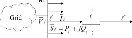
In a power grid, there often coexist several harmonic sources. Figure 1 shows a point of common coupling (PCC) connected to several lines. The harmonic voltage and current as well as complex power overline end-′, denoted by V′, I′ and S′, are responses under all harmonic sources action together. The level of harmonic pollution liability of a source should be decided by the ration of the source’s component contribution to the sum of component contributions over all sources.
For a harmonic wave over line end-′ (or the PCC), the liability of a source for harmonic pollution is defined as the ration of the source’s line-transferred component contribution to the sum of component contributions over all sources, and briefly called this source’s harmonic pollution liability.
Electrical quantities representing harmonics are harmonic current, voltage and power. Currently, there are only two quantitative liability division methods for harmonic pollution, one is based on harmonic current and the other is based on harmonic voltage. Assume that there are n harmonic sources in a grid. For line end-′, a source’s harmonic pollution liability based on harmonic voltage is calculated by
Grid
...
...
[image:2.595.198.428.632.699.2]PCC
100% v
k k
L =V′′ V′ × . (1)
v k
L is the harmonic pollution liability of source-k
(
k=1, 2,3,,n)
over line end-′. V′′k is the projectionof phasor V′k (response of harmonic voltage component over line end-′ under source-k action alone) on
phasor V′ (total response of harmonic voltage over line end-′).
A source’s harmonic pollution liability based on harmonic current is calculated by
100% v
k k
L =I′′ I′ × . (2)
v k
L is the harmonic pollution liability of source-k over line end-′. I′′k is the projection of phasor I′k (re-sponse of harmonic current component over line end-′ under source-k action alone) on phasor I′ (total re-sponse of harmonic current over line end-′).
As the voltage is an important power quality index, the research of voltage-based liability division method for harmonic pollution is relatively deeper than that of current-based one. The level of harmonic voltage (current) will increase sharply when series (parallel) harmonic impedances match in a grid. So the harmonic voltage- or current-based method can’t reflect completely the electrical characteristics of harmonics. In addition, the calcu-lation of voltage- or current-based harmonic pollution liability needs the projection of component on the total, which makes not only the physical meaning inexplicit but also the divergence in the level of harmonic pollution liabilities big [12]. Thus, it would be more complete and reasonable to take into account both harmonic voltage and current, or take into account harmonic power, in determining harmonic pollution liability. However, there is no power-based quantitative liability division method for harmonic pollution till now. This is because “power does not meet the superposition theorem”. In this paper, employing our achievements, two liability division me-thods for harmonic pollution based on harmonic power are proposed.
3. Liability Division Method for Harmonic Pollution Based on Power
3.1. Theory of Line-Transferred Power Component
By circuit theory, power does not meet the superposition theorem. In order to quantitatively divide the harmonic pollution liability among sources based on power, source-k-driven line-transferred complex power component under coexistence of all harmonic sources must be determined at first. A formula for determining source-k-driven line-transferred complex power component is derived and proved in [13] [14] based on the additive, effective-ness and symmetry, which complies with the circuit laws without any assumption.
1 1
0.5 0.5
n n
k k k k k
k k
S′ V′ I∗′ I∗′ V′
= =
=
∑
+∑
. (3)
k k k
S′ =P′ + jQ′ is the source-k-driven line-end-′-transferred complex power component. P′k and Q′k
are the real and imaginary parts of S′k. I∗′k is the conjugation of I′k. Obviously, the sum of line-end-′- transferred complex power components over all sources is equal to the total complex power over line-end-′.
1 n
k k
S′ S′ =
=
∑
. (4)
S′=P′+ jQ′ is the total complex power over line-end-′ under all sources action together. P′ and Q′
are the real and imaginary parts of S′.
With formula (3), the harmonic pollution liability can be quantitatively divided among harmonic sources based on power.
3.2. Liability Division Method for Harmonic Pollution Based on Line-Transferred Active
Power Component
100%
p
k k
L =P′ P′× . (5)
p k
L is the harmonic pollution liability of source-k over line end-′ based on line-transferred active power component.
3.3. Liability Division Method for Harmonic Pollution Based on Line-Transferred Complex
Power Component
Similar to the quantitative liability division methods for harmonic pollution based on voltage or current, the projection of phasor S′k on phasor S′ can be used to quantitatively divide the harmonic pollution liabil-ity of source-k over line end-′. As a result, a source’s harmonic pollution liability based on line-transferred complex power component can be determined by
100% s
k k
L =S′′ S′ × . (6)
s k
L is the harmonic pollution liability of source-k over line end-′ based on line-transferred complex pow-er component. S′′k is the projection of phasor S′k on phasor S′.
4. Case Study
The two newly proposed methods for quantitative division of harmonic pollution liability, represented by (5) and (6), are based on line-transferred active-and complex-power components, and called P-method and
S-method, respectively. A case study is performed to show the effectiveness of the two methods. And the simulation results by the voltage- and current-based methods (respectively called V-method and I-method) are also given for comparison.
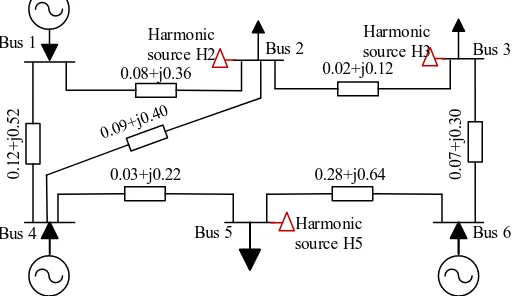
The IEEE 6-bus system shown in Figure 2 is used for the test. The system contains three generators, six bus, and seven transmission lines. Line impedances (in p.u.) at rated frequency are also shown in the figure.
Assume that there are three harmonic sources (their frequency is 5 times of the rated) located at busses 2 and 3 as well as 5, and denoted by H2 and H3 as well as H5, respectively. In the test, all harmonic sources are represented by ideal equivalent current source, all loads in the harmonic domain are represented by im-pedance model II as in [15]. The harmonic currents of the three harmonic sources are 0.3780 + j0.2823, 0.8193 + j0.6608 and 0.9450 + j1.0318 p.u., respectively.
In order to obviously show the features of the four harmonic pollution liability division methods (P-me- thod, S-method, V-method and I-method), only the simulation results of the six lines, 2-1, 2-3, 3-6, 4-2, 5-6, 5-4, are selected and listed in Table 1-3.
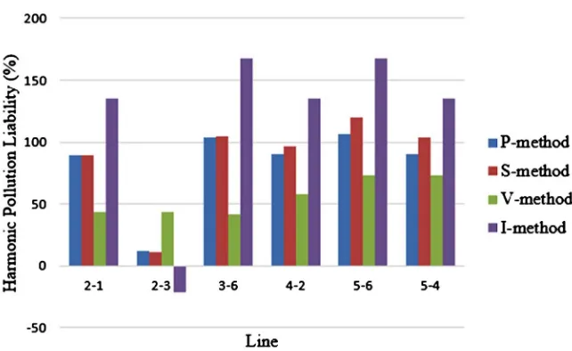
For intuitiveness, the bar graphs of one source’s harmonic pollution liabilities over individual lines by different methods are shown in Figure 3-5.
[image:4.595.186.444.553.701.2]Look at the H3’s harmonic pollution liabilities shown in Figure 3 and Table 1: By I-method, the range of the harmonic pollution liabilitiesis [–58.681%, 176.646%], the biggest of all. The standard deviation of them
Figure 2. The IEEE 6-bus system.
Bus 1 Bus 2 Bus 3
Bus 4 Bus 5 Bus 6
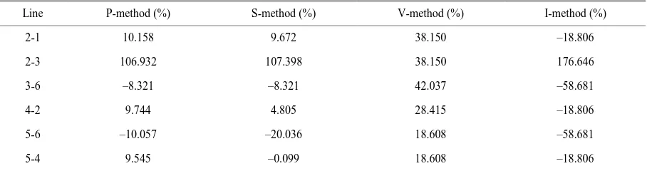
Table 1. Liabilities of H3 for line-end harmonic pollution by different methods.
Line P-method (%) S-method (%) V-method (%) I-method (%)
2-1 10.158 9.672 38.150 –18.806
2-3 106.932 107.398 38.150 176.646
3-6 –8.321 –8.321 42.037 –58.681
4-2 9.744 4.805 28.415 –18.806
5-6 –10.057 –20.036 18.608 –58.681
5-4 9.545 –0.099 18.608 –18.806
Table 2. Liabilities of H2 for line-end harmonic pollution by different methods.
Line P-method (%) S-method (%) V-method (%) I-method (%)
2-1 0.734 0.754 18.054 –16.545
2-3 –18.810 –18.730 18.054 –55.514
3-6 4.609 4.030 16.674 –8.615
4-2 0.486 –1.377 13.791 –16.545
5-6 4.153 –0.026 8.563 –8.615
5-4 0.734 0.754 18.054 –16.545
Table 3. Liabilities of H5 for line-end harmonic pollution by different methods.
Line P-method (%) S-method (%) V-method (%) I-method (%)
2-1 89.107 89.573 43.796 135.351
2-3 11.878 11.332 43.796 –21.132
3-6 103.712 104.292 41.288 167.296
4-2 89.770 96.572 57.794 135.351
5-6 105.904 120.063 72.829 167.296
[image:5.595.84.541.250.370.2]5-4 90.088 104.090 72.829 135.351
Figure 4. Bar graphs of H2’s harmonic pollution liabilities versus lines.
Figure 5. Bar graphs of H5’s harmonic pollution liabilities versus lines.
is 0.885, also the biggest of all. It indicates that the I-method is the most unreasonable and extreme method.
By V-method, the range of the harmonic pollution liabilitiesis [18.608%, 42.037%], the smallest of all. The
standard deviation of them is 0.104, also the smallest of all. Thus V-method goes to another extreme opposite to the I-method. By P-method and S-method, the range of the harmonic pollution liabilities are respectively [−10.057%, 106.932%] and [−20.036%, 107.398%], the medium among all. The standard deviations of them are respectively 0.437 and 0.462, also the medium among all. Both P-method and S-method are reasonable viewing from the ranges of their harmonic pollution liabilities.
The real part of a complex power means the average power delivered by the grid, while the imaginary part of a complex power is the amplitude of power travelling back and forth in the grid. Their physical meanings are quite different. In addition, the S-method needs projection of complex power component on total com-plex power. These make the S-method inexplicit in physical meaning.
In conclusion, the P-method (liability division method for harmonic pollution based on line-transferred active power component) is the most ideal method, which is not only explicit in physical meaning but also complete and reasonable.
[image:6.595.153.474.304.501.2]5. Conclusions
The range and standard deviation of liabilities for harmonic pollution by the current-based method are the big-gest of all. Those by the voltage-based method are the smallest of all. The two methods go to opposite extremes and are unreasonable. The newly proposed two methods, which respectively based on line-transferred active power component and line-transferred complex power component, take all factors into account (complete) and give reasonable levels of liabilities for harmonic pollution.
However, the method based on line-transferred complex power component needs projection of the complex power component, thus inexplicit in physical meaning. As a result, the liability division method for harmonic pollution based on line-transferred active power components is not only complete and explicit but also reasona-ble, and it is worth of recommendation.
Funding
This work is supported by National Natural Science Foundation of China under grant 51177102.
References
[1] Srinivasan, K. (1996) On Separating Customer and Supply Side Harmonic Contributions. IEEE Transactions on Power
Delivery, 11, 1003-1012. http://dx.doi.org/10.1109/61.489362
[2] Shi, L.J. and Zhao, J.G. (2002) Application of Active Power Filter to Improve Power Quality. Proceedings of the EPSA,
14, 36-306.
[3] Hu, M. and Chen, H. (2000) Survey of Power Quality and Its Analysis Method. Power System Technology, 24, 36-38.
[4] Gursoy, E. and Niebur, D. (2009) Harmonic Load Identification Using Complex Independent Component Analysis.
IEEE Transactions on Power Delivery, 24, 285-292. http://dx.doi.org/10.1109/TPWRD.2008.2002968
[5] McEachern, A., Grady, W.M. and Moncrieff, W.A. (1995) Revenue and Harmonicsan Evaluation of Some Proposed
Rate Structures. IEEE Transactions on Power Delivery, 10, 123-128. http://dx.doi.org/10.1109/61.368364
[6] Hui, J., Yang, H.G. and Ye, M.Q. (2011) Research on the Liability Partition of Harmonic Pollution of Multiple
Har-monic Sources. Proceedings of the CSEE, 31, 48-54.
[7] Sun, Y.Y. and Yin, Z.M. (2012) Quantifying Harmonic Responsibilities of Multiple Harmonic Sources Based on M-
Estimation Robust Regression. Proceedings of the CSEE, 32, 166-173.
[8] Jia, X.F., Hua, H.C., Cao, D.S. and Zhao, C.Y. (2013) Determining Harmonic Contributions Based on Complex Least
Squares Method. Proceedings of the CSEE, 33, 149-155.
[9] Ma, H.Z., Xu, G., Song, S.P., Zhao, H.F. and Ren, L.Z. (2014) Quantitative Analysis of Harmonic Current Liability in
Distribution Network. Eclectic Power Automation Equipment, 34, 44-49.
[10] Xu, J.Z., Pang, L.Z., et al. (2012) Quantitative Analysis for Harmonic Liability Proration among Multiple Harmonic
Sources. Electric Power Automation Equipment, 32, 38-42.
[11] Ye, J. (2010) A Liability Sharing Method Based on Harmonic Power. Journal of Electric Power, 25, 210-213.
[12] Hua, H.C., Jia, X.F., Cao, D.S. and Zhao, C.Y. (2013) Harmonic Contribution Estimation under Power Quality Data
Interchange Format. Power System Technology, 37, 3110-3117.
[13] Peng, J.C. (2005) Definitions of Branch’s Originating Power Component and Branch’s Driven Power Component and
Their Analysis. Power System Technology, 29, 24-29.
[14] Peng, J.C., Zeng, Y.G. and Jiang, H. (2012) Resolution of Line-Transferred Power in Grids Yielded by Circuit-Laws’
Symmetry under Deductive Reasoning of Shapley Theorem. IET Generation, Transmission & Distribution, 6, 627-
635. http://dx.doi.org/10.1049/iet-gtd.2011.0536
[15] Burch, R., Chang, G., Hatziadoniu, C., et al. (2003) Impact of Aggregate Linear Load Modeling on Harmonic Analysis:
A Comparison of Common Practice and Analytical Models. IEEE Transactions on Power System, 18, 625-630.