© 2018, IRJET | Impact Factor value: 6.171 | ISO 9001:2008 Certified Journal | Page 2827
Design of Slotted Microstrip patch Antenna for 5G Application
Nikita M. Tarpara
1, Raju R. Rathwa
2, Dr. Nirali A. Kotak
31,2 EC Department , L.D. College of Engineering
3 Prof. at EC Department, L.D. College of Engineering, Gujarat, India
---***---Abstract -
The 5G cellular system is expected to have a widespectrum. The antenna design for 5G application is challenging task. This paper consists of the antenna design for the 5G application which will use microstrip patch antenna with slots loaded on the radiating patch to improve the performance of antenna in terms of gain, radiation pattern and bandwidth at 5-6GHz spectrum. Microstrip antennas have several advantages like low profile, low cost and ease of fabrication. Major disadvantage of the microstrip patch antenna is its inherently narrow impedance bandwidth. By loading some specific slot in the radiating patch of microstrip antennas, compact or reduced size microstrip antennas can be obtained. Loading the slots in the radiating patch can cause meandering of the excited patch surface current paths and result in lowering of the antenna’s fundamental resonant frequency, which corresponds to the reduced antenna size for such an antenna. In this paper FR4 material is used for the 1.6mm thick substrate.
Key Words: Slotted patch antenna, Return loss, Bandwidth, VSWR
1. INTRODUCTION
In today’s wireless communication , the most important requirement is of antenna with low profile. Most probably for the handheld devices, the challenging task is to design antenna which provide improved performance day by day with miniaturized size. The most probably preffered and extensively used antennas are Microstrip antennas because of easy to integrate with circuits.
5G Technology means 5th Generation Mobile Technology. 5G technology will use cell phones within very high bandwidth. 5G is a packet switched wireless system with wide area coverage and high throughput. 5G technology use millimeter wireless will have data rate greater than 100Mbps at full mobility and higher than 1Gbps at low mobility. The 5G technology will include all types of advanced features which make 5G technology most powerful and in huge demand in the near future. Such a huge collection of technology being integrated into a small device. The 5G technology provides the mobile phone users more features and efficiency.
Microstrip antenna consist of patch which is very thin metallic strip or sheet placed above ground plane separated by a substrate of dielectric material. The performance of the microstrip antennas depends on the height of the substrate and dielectric constant of substrate. The performance of microstrip antennas are good for thick substrate with lower dielectric constant of substrate material. The major limitation
of Microstrip antenna is impedance bandwidth is lower for thin substrate. But for the handheld devices and wireless communication , the antenna size should be small and for that the height of substrate should be as small as possible.
This paper mainly contains the sections in which design equations of conventional rectangular radiating patch, technique to improve performance of antenna with loading slot on radiating patch, theoretical calculation of Return loss and VSWR and proposed antenna for 5G application are described.
2. DESIGN EQUATIONS OF MICROSTRIP ANTENNA Microstrip antennas consist of patch which is a sheet or thin metallic strip placed on a substrate of dielectric material. The shape of the patch may be rectangular, triangular, circular ,square or of any type. The dielectric constant of material should be in between 2.2 to 12 for antenna designing[3]. The height of the substrate, h ˂˂ λ0 [3] (whrere,
λ0= operating wavelength). The designing parameters of
microstrip patch antennas for rectangular patch are length of patch(L) and width of patch(W). These two parameters are depends on the height of substrate, dielectric constant of material and resonant frequency(Resonant frequency should be same as operating frequency).
In the Microstrip antennas, the patch is main radiating element. For rectangular patch, the width of the patch(W) is depends on the resonant frequency(fr) and dielectric constant(εr) of the material, which is given by[3],
0 0
1 2
1
2 r r
W
f
(1)
The effective dielectric constant is introduce to account for fringing effect because some of the waves travel in the substrate and some of in the air.
For W/h ˃ 1, the effective dielectric constant is[3],
1 - 2
1
-1
1 12
2
2
r r reffh
W
(2)The electrical length of patch is greater than the physical length because of fringing effect. If extended dimension of the patch length is ∆L , then
© 2018, IRJET | Impact Factor value: 6.171 | ISO 9001:2008 Certified Journal | Page 2828 Thus the actual length of patch is,
(4)
3. ANALYSIS OF SLOT LOADED PATCH ANTENNA 3.1 Analytical Calculations of slot
In the conventional Microstrip antenna, the rectangular slot is loaded on the radiating patch as shown in figure1, of length Ls and width a. It is also necessary to load the slot on patch with proper dimensions such that it can improve the performance of antenna the antenna compared to the performance of conventional antenna. In this section, the slotted Microstrip patch antenna is analyzed. The slot on patch can be analyzed by using duality relationship between the dipole and the slot[2].
The slot loaded on the patch affect to the performance parameter of the antenna. The slot loaded rectangular microstrip patch antenna can be considered as parallel combination of capacitance C1, inductance L1 and resistance
R1 of patch and capacitive reactance of slot[2].
[image:2.595.370.466.200.240.2]Fig-1: Slot loaded rectangular Microstrip patch antenna
Fig-2. Equivalent circuit of slot loaded on patch
(5)
(6) (7)
h = Thickness of substrate = Effective dielectric constant
= Permittivity of free space z0 = Feed point location along z-axis
The input impedance (Zin) of the above excluding slot can
be expressed as, 1 1 1 1 1 1 in Z j C R j L
Then above expression can be expressed as, (8)
Fig-3: Modified Equivalent circuit of slot loaded on patch
The input impedance of slot loaded on patch can be calculated using above Figure 4 as,
Reflection coefficient,
Return Loss = (9)
1+ Γ
VSWR=
1- Γ
(10)Thus return loss and VSWR affect by the slot on patch. Bandwidth is depend on the return loss and VSWR plot. So bandwidth also affect by the slot on patch.
3.2 Theoretical Calculations of slot
The slotted Microstrip antenna is analyzed in above section and in this section the value of Return loss and VSWR are calculated theoretically using equations described in (III) for different slot widths and slot lengths. The patch was designed for frequency 3.0GHz , dielectric material of substrate RT Duriod (εr=2.2) and thickness of substrate is
0.0159λ.
0 0
1
2 2 r reff
L L
f
0 2 0
1 cos
2
eff LW z
C h L 1 2 1 1 r L C 1 1 r Q R C eff
0
-inZ
R jX
. . - -s s ins sX X jR X
Z
R j X X
[image:2.595.58.261.380.510.2] [image:2.595.322.542.480.607.2]© 2018, IRJET | Impact Factor value: 6.171 | ISO 9001:2008 Certified Journal | Page 2829
(i)
(ii)
(iii)
[image:3.595.61.552.51.799.2](iv)
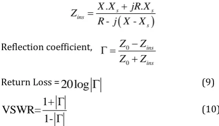
Figure 4. variation in VSWR Vs frequency in GHz for different slot width(a) for given slot length(Ls); (i) Ls=10mm, (ii)
Ls=12mm, (iii) Ls=14mm, (iv) Ls=16mm
(i)
(ii)
(iii)
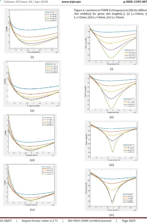
© 2018, IRJET | Impact Factor value: 6.171 | ISO 9001:2008 Certified Journal | Page 2830 Figure 5. variation in return loss Vs frequency in GHz for
different slot width(a) for given slot length(Ls); (i) Ls=10mm,
(ii) Ls=12mm, (iii) Ls=14mm, (iv) Ls=16mm
From the Figure 4 and 5, it can be observed that resonance frequency decreases with increasing slot width for same slot length. The bandwidth or frequency variation is more for lowest slot length with same slot width. The value of VSWR and return loss also decreases as slot width increases. 4. ANTENNA DESIGN
The antenna design consist of choice of substrate material and thickness of the substrate. The FR4 material is used for the 1.6mm thick substrate at 5-6GHz spectrum of 5G. The conventional patch antenna is as shown in figure 6.
[image:4.595.311.558.77.268.2]Fig-6. Conventional Patch Antenna Table 1: Design Parameters of Patch Length
of patch L(mm)
Width of patch W(mm)
Height of substrate h(mm)
Width of feed line(mm)
Length of substrate Lg
Width of substrate Wg
12.62 16.59 1.6 2.98 6h+L 6h+W
The above patch antenna is simulated using HFSS.
(i)
(ii)
Figure 7. (i) Return loss(dB) Vs Frequency plot(GHz) (ii)gain(dB) Vs Theta(deg) plot of conventional antenna From figure 7, it can be seen that the resonant frequency is 5.4GHz, return loss at resonant frequency is -10.97dB, bandwidth is 167MHz and gain is 2.65dB.
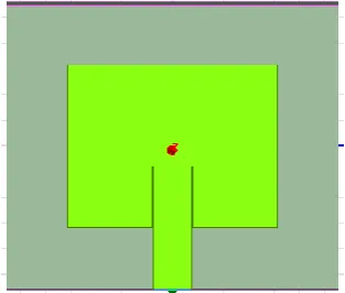
Now the requirement for the 5G application about gain is that gain should be more than 5dB. The gain can be improved by the array of patches but it does not affect to the bandwidth. Thus to increase the bandwidth, one slot is loaded on the radiating patch of the antenna as shown in figure 8.
The length of the slot is 7mm and width of slot is 2.1mm. By simulating this slotted antenna resulting in return loss of -11.83dB at resonant frequency 5.4GHz. The bandwidth is 201MHz and gain is 2.38dB. Thus bandwidth is increases by slot on patch but it does not affect to the gain of patch.
[image:4.595.83.240.274.407.2] [image:4.595.40.535.470.782.2] [image:4.595.347.521.503.656.2]© 2018, IRJET | Impact Factor value: 6.171 | ISO 9001:2008 Certified Journal | Page 2831 (i)
(ii)
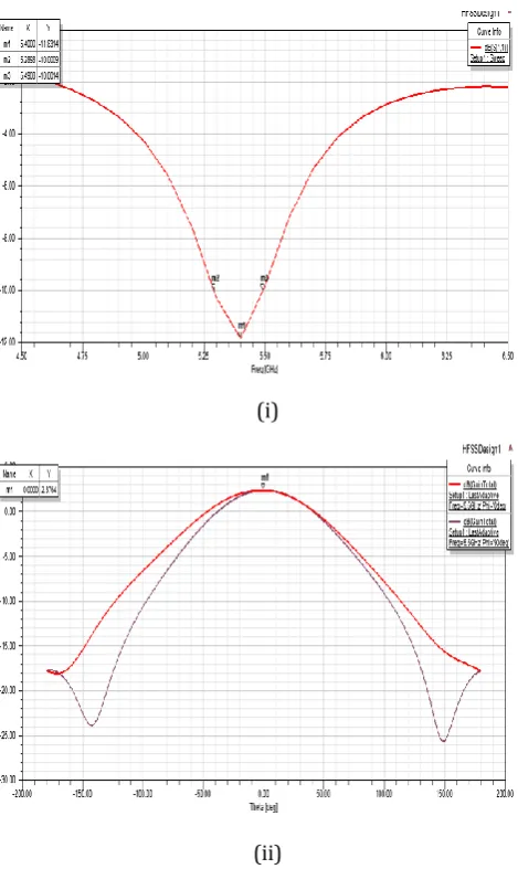
Fig-9: (i) Return loss(dB) Vs Frequency plot(GHz) (ii)gain(dB) Vs Theta(deg) plot of slotted antenna Now for the proposed antenna for 5G application, array of patch is used to increase the gain and slot is used to increase the bandwidth as shown in figure 10.
Fig-10. Proposed antenna
(i)
(ii)
Figure 11. (i) Return loss(dB) Vs Frequency plot(GHz) (ii)gain(dB) Vs Theta(deg) plot of proposed antenna The patches are placed on λ/2 distance fron each other. From figure 11, it can be seen that bandwidth increases and it is 672.8MHz because of slots on patch. The gain of patch due to array of patch and it is 5.72dB.
5. CONCLUSION
By loading the slot, resonant frequency can be decreases and bandwidth of antenna increases. Resonant frequency varies slightly for different slot width as compared patch without slot. The bandwidth is also increases with slot width for given slot length. Gain and bandwidth both can be increased by array of patch with slots on each patch. REFERENCES
[1] M.A.Matin, A. I. Sayeed, “A Design Rule for Inset-fed
Rectangular Microstrip Patch Antenna”, WSEAS Transactions on Communications ,vol. 9, pp. 63-72, January 2010.
[2] Shivnarayan, Shashank Sharma, Babau R Vishvkarma,
[image:5.595.308.553.59.441.2] [image:5.595.40.275.74.468.2] [image:5.595.39.288.552.698.2]© 2018, IRJET | Impact Factor value: 6.171 | ISO 9001:2008 Certified Journal | Page 2832
[3] C.A.Balanis, “Antenna Theory , Analysis and Design ”,
3rded.
[4] Muhammad Umar Khan, Mohammad Said Sharawi, Raj
Mittra, “Microstrip patch antenna minituarization techniques: a review”, IET Microwaves, Antennas & Propagation, vol. 9, pp. 913-922, 2015.
[5] Ranjan Mishra, Raj Gaurav Mishra, Piyush Kuchhal,
“Analytical Study on the Effect of Dimension and Position of Slot for the Designing of Ultra Wide Band (UWB) Microstrip Antenna”, Intl. Conference on Advances in Computing, Communications and Informatics (ICACCI), pp. 488-493, September 2016.
[6] Ulas Keskin, Bora Doken, Mesut Kartal, “Bandwidth
improvement in microstrip patch antenna”, 8th International Conference on Recent Advances in Space Technologies (RAST), IEEE Conference, pp. 215-219,June 2017.
[7] Girish Kumar, K.P.Ray, “Broadband Microstrip
Antennas”, Artech House.
[8] Dinesh Yadav,“L- Slotted Rectangular Microstrip Patch
Antenna”,2011 International Conference on
Communication Systems and Network Technologies, IEEE Conference, pp.220-223, June 2011.
[9] Kin-Lu Wong, “Compact and Broadband Microstrip
Antennas”, A Wiley Inter science Publications.
[10] Mohamed Mamdouh M. Ali, Osama Haraz, Saleh
Alshebeili, Abdel-Razik Sebak, "Broadband printed slot antenna for the fifth generation (5G) mobile and wireless communications”,2016 17th International Symposium on Antenna Technology and Applied Electromagnetics (ANTEM) , July 2016.
[11] Alak Majumder, “Rectangular Microstrip Patch Antenna
Using Coaxial Probe Feeding Technique to Operate in S-Band”, International Journal of Engineering Trends and Technology (IJETT),vol. 4,pp. 1206-1210,April 2013
[12] Wonbin Hong, Kwang-Hyun Baek, Seungtae Ko,
“Millimeter-Wave 5G Antennas for Smartphones: Overview and Experimental Demonstration”, IEEE Transactions on Antennas and Propagation, vol. 65, pp. 6250 – 6261.
[13] Wei Hong, Zhi Hao Jiang, Chao Yu, Peng Chen, Zhiqiang
Yu, “Multi- Beam Antenna Technologies for 5G Wireless Communications”, IEEE Transactions on Antennas and Propagation 2016
[14] S. E Jasim, M. A. Jusoh, M. H. Mazwir and S. N. S. Mahmud,