Study of Meshing Methods for Single Strap Butt Welded Specimen using
FEM
Satyaveer Rajput
1Sudhir Sharma
21
M.Tech Student
2Assistant Professor
1,2Department of Mechanical Engineering
1,2
I.P.S. College of Technology & Management, Gwalior, M.P., India
Abstract— The welding technology in today’s world is improving with the application of Numerical simulation. Also this leads to the improvement of overall fabrication process. Present paper represents the various aspects of lap & butt weld. Present work includes the review of weld types, weld geometries boundary conditions with wide amounts of literature study conducted for this work. Present paper focuses on single cover plate butt type of weld. ANSYS which is a Finite Element Analysis (FEA) tool is used to simulate the lap weld. Study of different meshing methods with some necessary variations is done in this work.
Key words: Finite Element (FE), Lap & Butt Weld, ANSYS, Meshing, Welding
I. INTRODUCTION
Among the most widely used structural materials in the civil & mechanical engineering practice are structural steels. Welding which is already widely used in workshops in the steel industries has also become relevant for on-site constructions. Also, to speed up manufacturing processes & improving productivity and quality of steel structures together, are among the fundamental expectations in today’s world.
It was impossible to simulate the welding of complex structures & machine parts, several years ago. This was due to the hardware requirements & the long time required for computation. The improvements in computational background made it feasible to examine large scale welded joints with enough accuracy. FEA- finite element analysis can be used to design the parts considering DFM- design for manufacturing aspect as well. The numerical simulations became more important due to the demand of high production quality & sustainable designs.
It is practically impossible to achieve 100% efficiency for weld. In a welding assembly, the most vital components are weld toes and weld roots where maximum amount of stress and failure occurs. Continuous thermal cycle by heat input generates the residual stresses and distortion. This leads to fatigue failure in the weld assembly.
II. TYPES OF WELDED JOINTS
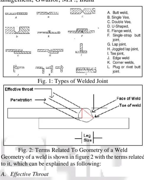
[image:1.595.305.549.149.453.2]There are numerous types of welded joint classified on the various bases. Some of them are butt weld, single Vee, double vee, U-shaped, flanged weld, single strap butt weld,lap joint, joggled lap joint, edge joint, tee joint, corner weld, plug or
Fig. 1: Types of Welded Joint
Fig. 2: Terms Related To Geometry of a Weld Geometry of a weld is shown in figure 2 with the terms related to it, which can be explained as following:
A. Effective Throat
The minimum distance from the root to the face of the weld. It is also known as the effective area of welded joint.
B. Face of Weld
The exposed surface left after the weld bead formation. It is the visible side of the weld among the three sides shown in the figure 2.
C. Root
The point where the two plates & the weld meet. It is also the point where weld material end common point of two flanges.
D. Toe of Weld
The point where face of the weld, meet the bottom or top base plate.
E. Leg Size
The distance between the root of weld to the toe is known as leg size.
beam. The effect of face-to-face contact of the top and bottom metal sheets of welded lap joints is considered using a modified material model for the thermo-mechanical analysis. There are two stress existing in the HAZ near weld pool - the normal stress components in the weld zone during hybrid welding process, and maximum thermal stress exceeding the yield point of material. Width of weld bead to decreases, and the thermal stress concentration at the welded joint reduces with increase in welding speed. Longitudinal tensile stress (SZ) and transverse compressive stress (SX) are retained in the formed weld after cooling where longitudinal compressive stress is higher around the weld bead. The residual stress concentration in the weld joint obtained by hybrid laser–GTAW is the minimal compared to the welded joint obtained by GTAW and laser welding alone.
Reference [2] introduced a numerical simulation model to predict the residual stress and distortion fields for LBW with reliable outcomes. A thermal analysis is conducted for Aluminum 6061-T6 lap joints to analyze the spatial temperature distribution history as laser beam welding (LBW) is a thermo-mechanical process. The residual stresses and distortions are obtained from mechanical analysis. The keyhole size and shape is predicted by introducing an innovative keyhole model required for the thermal analysis. Heat radiation, thermal conduction and convection heat losses and all major physical phenomenon of LBW are considered to form such model. The efficiency of this model is observed for the lap-joint weld of two 6061-T6 aluminum plates which already stand good for butt joint welding of DH-36 steel plates. As the temperature & phase variations are large, the material properties are considered temperature function. The algorithm of the model is programmed within ANSYS- finite element code. Since the simulation model can be applied to wide range of LBW as it is independent of any empirical parameter and problems, geometry, material and joint type. Only basic mechanical and thermal material properties are required to perform simulation using this model.
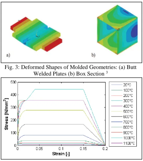
[image:2.595.306.554.65.344.2]Reference [3] investigated the effects of different welding parameters - heat input, welding speed, steel grade, on residual stresses and deformations. He concentrated on heat sources, temperature dependent material properties and the development of an uncoupled thermo-mechanical analysis. The first specimen, structural steel S355 as per the Eurocode 3 (EC3): EN1993-1-2:2005 (Design of steel structures for Structural fire design), in the form of butt welded plates in Fig.3 (a), joined with Metal Active Gas (MAG) welding, are of length=700 mm width=120 mm & thickness=16 mm. The second specimen, butt welded box section in Fig.3 (b) had length of the specimen equal to the width i.e. of 400 mm with plate thickness of 8 mm. The applied steel material is S355 as per EC: EN1993-1-5.
Fig. 3: Deformed Shapes of Molded Geometries: (a) Butt Welded Plates (b) Box Section 3
Fig. 4: Applied Stress Strain curve for Structural Steel S355 at Different Temperatures 3
[image:2.595.309.549.517.638.2]Fig. 5. (a): Verification of the numerical model by temperature curves (b) Finite element model for multi-pass
butt welded plate 3
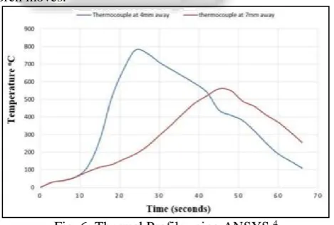
[image:3.595.48.285.65.228.2]Reference [4] carried out analysis of stresses in heat affected zone (HAZ) and welded zone for a Ferritic Stainless Steel- 409M stainless steel (FSS) specimen after single pass Shielded Metal Arc Welding (SMAW). They wanted to study & analyze the temperature fields and stress distribution for FSS409M using 3-D FE model in ANSYS 14. The two work-pieces of dimension 150*75*4 were developed in APDL and were glued. The material, with orthotropic material properties, is meshed using a brick element called SOLID70 & Solid 185, which are 8 noded three dimensional elements. The heat flux provided in thermal analysis was calculated using Goldak’s heat source model. The transient thermo-mechanical (coupled) analysis shows temperature and residual stress distributions on welded plates. In order to find out the temperature profile at heat affected zone from starting point of welding. The thermocouples were inserted at a distance of 50mm and 100mm. Following figure 6 shows the temperature distribution at heat affected zone as the welding torch moves.
Fig. 6: Thermal Profile using ANSYS 4
Reference [5] studied welded T-joint under coupled stress and energy criterion for which fatigue threshold value and fatigue limit are the two fundamental material parameters using Finite Element Analysis. This is done to find the effects
[image:3.595.308.554.239.367.2]Reference [6] conducted an investigation to find the temperature dependent shear coefficient to be used in a 3D numerical model of the process of Linear Friction Welded (LFW) AA2011-T3 aluminum alloy specimen. Shear stress at the interface is calculated using the observations of Torque, oscillation frequency and pressure. The numerical thermal model is obtained from the data of thermocouple attached to the specimen. The 3D model of the thermo-mechanical contact between the two specimen, of Lagrangian & rigid-viscoplastic in nature, is developed by employing calculated shear coefficient. Variation in LFW process parameters lead to a curve of temperature vs narrow range of variation of the shear factor as shown in fig 7. Temperature predicted for the 3D model of the process was also found to have a good agreement.
Fig. 7: Curve of Temperature vs Narrow Range of Variation of the Shear Factor 6
Reference [7] conducted a study to assess the influence of process induced residual stresses on the fatigue behavior of friction stir welded butt joints. They used Finite Element Method (FEM) and Dual Boundary Element Method (DBEM) for this. Simulation of multiple crack propagation done by studying the distribution of the process induced residual stresses using contour method- computed residual stress field is superimposed to the stress field into DBEM platform. Crack propagation rate assessment was done on the basis of two-parameter crack growth law. Stress Intensity Factors are evaluated by the J-integral technique. Constant amplitude crack propagation tests gives Computational results vs. experimental data, which shows of crack initiation and crack propagation, the two subdivision of the overall fatigue life of the sample.
Reference [8] investigated the predictions of fatigue crack growth under wide spectrum of load utilizing coupled FEM-DBEM approach. Pre-notched specimen of aluminum alloy is machined in the central part in order to reduce the resistant section and facilitate the crack initiation from a triangular notch obtained with a thin saw cut. Two parameter crack growth law (eq.1), also called Unified Approach in their research, and is applied for the constant amplitude experimental tests.
da
dN= A (∆K − ∆Kth
∗ )m(Kmax− ∆K max,th
∗ )n (1)
[image:3.595.50.285.476.634.2]Reference [9] analysed the thermal stress for a laser welded Low carbon steel specimen using FEM. Mild steel sheets of 20mm wide, 30mm long & 2mm thick is Laser welded under nitrogen assisting gas ambient. FEM is used to compute temperature and stress fields in the welding region. X-ray diffraction (XRD) technique is used to measure residual stress developed in the welding region and the results are compared with the predictions. The metallurgical examinations of the welding sites are conducted using Scanning electron microscopy (SEM) & Optical microscopy. It was observed that in the cooling cycle after the solidification of the molten regions, von Mises stress attains high values. The residual stress predicted hold agreement with the XRD observations.
Reference [10] assessed the fatigue strength of welded lap joints and cover plates with toe and root failures by adopting Peak Stress Method (PSM). PSM- method to estimate the notch-stress intensity factors, originally proposed only for mode I loading like at the toe of fillet-welds, which is extended to mode II loading. This lead to a design stress which is derived to readily assess either weld toe or weld root fatigue failures. An equivalent peak stress is derived from the extension PSM to mode II loading, which is used to assess either weld toe or weld root fatigue failures. The time expended to estimate the fatigue strength is reduced due to the application of PSM.
[image:4.595.209.533.83.758.2]IV. RESULTS & DISCUSSION
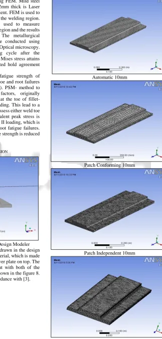
Fig. 8. Welded Joint Drawn in the Design Modeler Figure 8 illustrate the butt welded joint drawn in the design modeler, of structural steel as default material, which is made by joining two adjacent plates using a cover plate on top. The cover plate is making butt welded joint with both of the bottom plates. The ISO-metric view is shown in the figure 8. The dimensions of the above are in accordance with [3].
Automatic 10mm
Patch Conforming 10mm
Patch Independent 10mm
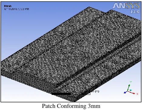
Patch Conforming 3mm
Fig. 9: Different Meshing Methods with Element Sizes Figure 9 shows the different meshing methods with element size considered. It is easy to observe the difference between the methods. It can be observed that the patch conforming method with 3 mm element size is the finest mesh. The patch conforming method in tetrahedron type is known to adjust the density of the mesh automatically at the patch areas like corners & vertices where the higher mesh density is required as different behavior at every node is expected under loading conditions. Also in this method the number of nodes is automatically kept optimum or less mesh density where the geometry is uniform i.e. similar behavior is expected at every node under loading conditions.
Type of meshing Element size Nodes elements
Automatic 10mm 24472 4550
Patch conforming
10mm 12403 6587
5 mm 44967 25026
3mm 135686 78095
Patch independent 10mm 77007 51035
[image:5.595.49.284.66.248.2]5 mm 665648 472371
Table 1: Meshing Methods with Number of Nodes & Elements for Different Elements Sizes
It can be noticed from table 1 that number of nodes and elements varies with meshing methods and element size. Density of mesh increases with increase in nodes & elements. For patch conforming method, with decrease in element size number of nodes and elements increases quickly. But notice that increment in number of nodes and elements fine the meshing but increases the solution time which can go up to days depends on nodes and element numbers.
V. CONCLUSIONS
1) FE analysis of butt weld has been conducted using ANSYS tool.
2) For appropriate meshing, tetrahedral and sizing meshing methods have been used for the welding root and toes in previous research work as per the literature review.
REFERENCES
[1] F. Kong & R. Kovacevic, “3D finite element modeling of the thermally induced residual stress in the hybrid laser/arc welding of lap joint,” Journal of Materials Processing Technology, Vol. 210 (6–7), 2010, pp.941-950.
[2] G. A. Moraitis, G. N. Labeas, “Residual stress and distortion calculation of laser beam welding for aluminum lap joints,” Journal of Materials Processing Technology, Vol. 198 (1-3), 2008, pp.260-269.
[3] Kollár, Kövesdi & Néző, “Numerical Simulation of Welding Process – Application in Buckling Analysis,” Periodica Polytechnica Civil Engineering, Vol. 61(1), 2017, pp.98–109.
[4] Deogade, Ambade & Patil, “Finite Element Analysis of Residual Stresses on Ferritic Stainless Steel using Shield Metal Arc Welding,” International Journal of Engineering Research and General Science, Vol. 3(2), 2015, pp.1131-1137.
[5] D. Wang, H. Zhang, B. Gong & C. Deng, “Residual stress effects on fatigue behaviour of welded T-joint: A finite fracture mechanics approach,” Materials & Design, Vol. 91, 2016, pp.211-217.
[6] G. Buffa, M. Cammalleri, D. Campanella & L. Fratini, “Shear coefficient determination in linear friction welding of aluminum alloys,” Materials & Design, Vol. 82, 2015, pp.238-240.
[7] R. Citarellaa, P. Carlonea, R. Sepeb & M. Leporea, “DBEM crack propagation in friction stir welded aluminum joints,” Advances in Engineering Software, Vol. 101, 2016, pp.50-59.
[8] R. Citarellaa, M. Leporea, M. Perrellaa, R. Sepeb & G. Cricrìa, “Coupled FEM-DBEM Simulation of 3D Crack Growth under Fatigue Load Spectrum,” Procedia structural Integrity, Vol. 2, 2016, pp.2631-2642. [9] B. S. Yilbas, A. F. M. Arif & B. J. A. Aleem, “Laser
welding of low carbon steel and thermal stress analysis,” Optics & Laser Technology, Vol. 42 (5), 2010, pp.760-768.