Using Non Linear Average Model of NPC Inverter
in DTC Control of Synchronous Machines
OMRI Bessem
ENIS -Sfax-Tunisia
Ammous Kaiçar
ENIS -Sfax-Tunisia
ABSTRACT
The Direct Torque Control (DTC) is known as an effective control method for high performance drives in a wide variety of industrial applications. This paper presents the Direct Torque Control (DTC) of an asynchronous machine fed by three levels NPC inverter. This inverter provides nearly sinusoidal voltages with very low distortion, using less switching devices. Due to the small dv/dt’s, torque ripple is greatly reduced. A nonlinear averaged modeling of the inverter was used to develop the control law. This kind of modeling allows a good tradeoff between simulation cost and precision. A simulation results are given to confirm the interest of the averaged modelling.
Keywords
Direct Torque Control, Three-Level NPC Inverter, and Nonlinear Average Modelling.
1.
INTRODUCTION
The Direct Torque Control (DTC) applied to the asynchronous machines appeared in the middle of 1980s. DTC is recognized today as a high-performance control strategy for AC drives [3-5]. The main objective of DTC is controlled the stator flux and electromagnetic torque by hysteresis regulators. This is to maintain torque and stator flux within the hysteresis band. DTC technique can give satisfactory results when multilevel inverters are used. This inverter provides nearly sinusoidal voltages with very low distortion, using less switching devices. Due to the small dv/dt’s, torque ripple is greatly reduced. However the simulation cost will increase if we consider the instantaneous model of multilevel inverter and induction machine.
The diffusion of the Computer Assisted Design (CAD) systems has made the need of analytic method for simulating power electronics systems. An averaged model including the nonlinear effects of the power semiconductor devices appear quite efficient. A powerful approach of average modeling and simulation of switch mode system is the equivalent of the circuit methodology. This modeling offers the best compromise between simulation cost and precision [1-2].
The work presented in this paper deals with a DTC algorithm designed for an induction machine when fed with three levels NPC inverter. For the simulation, we used our nonlinear average modelof the inverter developed in [2].This algorithm
does not require long computation time and is able to keep the motor torque and flux within a properly sized tolerance band.
In the following sections, after introducing the nonlinear average model of three levels NPC inverter, basic equations of flux and torque variations will be explored. Proper selection
of voltage vectors for controlling purposes will be followed and introduced in a table format. Finally, simulation results are given and discussed.
2.
NONLINEAR AVERAGE MODEL OF
MULTILEVEL NPC INVERTER
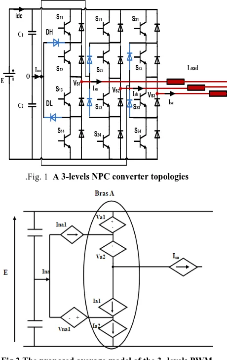
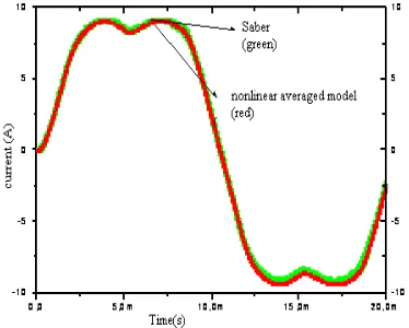
Based in our works describes in [2], we gives a nonlinear average model for the multilevel converter (Fig.1), in continuous conduction mode. The average model of one leg (A) of the inverter is represented in Fig.2. Isa represents the load average current of the legs (A). The model contains two controlled voltage source (Va1 and Va2) and two controlled current source (Ia1 and Ia2).
E C1
C2
S11
S12
S13
S14
S21
S22
S23
S24
S31
S32
S33
S34
DH
DL Vs1
Vs2
Vs3
Isb Isa
Isc
Ina Load
idc
O
[image:1.595.320.550.339.703.2].Fig. 1 A 3-levels NPC converter topologies
Fig.2 The proposed average model of the 3- levels PWM converter
Fig.3 Average representation of one leg of the 3-levels PWM converter
Where
1 2 1
na na a a
I I I I
1 2
a a a
V V V
2
a a
I I
The idea to compute the nonlinear average model of the multilevel converter consists in introducing the number of the sector which corresponds to a well defined type of commutation as being a parameter of the model. The dependent sources of the average model are calculated according to the nature of commutation and the different active components over this commutation.
The technique that we adopted to compute the nonlinear average model is based on the instantaneous evolutions of the currents and the voltages in each component over one modulation period Ts
.
We noted that the commutations obtained in this kind of converters are different from those obtained in the traditional converters based on the bidirectional current switches.From the curves representing the electric evolution states of the different components of the multilevel converter, we can compute the average values of the current sources and voltages sources over one period represented on the circuit of Fig. 1.
In order to demonstrate the accuracy of the proposed averaged model, a circuit model of the inverter implemented in Simpower Matlab simulator, using the circuit represented in Fig. 1 is used. For the simulation in this section and the section 5, we use 2GHz Core2 Duo processor and 3Go RAM.
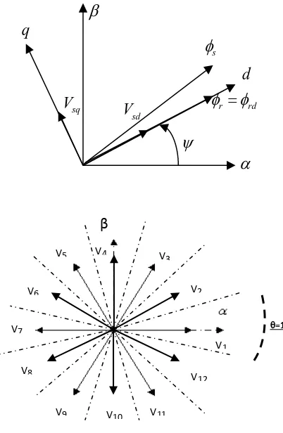
The comparison between the current waveforms (Fig.4) obtained by the SABER simulator and the current given by the proposed model shows the good accuracy of the nonlinear average model behavior for converter electric analysis. In Fig.5, we show the evolution of the dissipated power in the diode DH of three models: the developed nonlinear average model, the linear average model for multilevel inverter developed by K.AMMOUS [4] and the fine SABER model.
Fig.4 Current load for a leg obtained by Saber and the nonlinear averaged model (Load RL, R=20 Ω, L=10mH)
Fig.5 Losses in DH component obtained by Saber, linear and nonlinear averaged model (Load RL, R=20 Ω, L=10mH)
We notice that in the case of the single-phase NPC inverter, the simulation in Saber was completed in 40mn whereas with the nonlinear average model was completed in 6mn for one period of the inverter operation (20ms).
3.
BASIC EQUATION
3.1
Evolution of the stator flux
Referring to well-known flux and voltage equations of an induction machine and neglecting the stator resistance voltage drop, we can obtain the following relation describing the
variation of stator flux vector,s,when the voltage vector
, V s, is applied:
(
t
t
)
( )
t
Vs
.
t
s
s
(1)
In which
t
is the switching duration ofVs
. The stator flux variation vector has two components, one in along with thevector of stator flux,d, and the other perpendicular to it d
[image:2.595.86.247.71.220.2] [image:2.595.338.525.72.222.2] [image:2.595.333.532.257.420.2]s
.
s
Vs t
.
sd
V
t
.
sq
V
t
Fig.6 Stator flux variation components
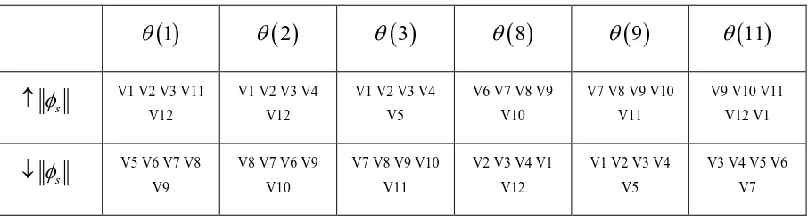
In Fig.7, we represent the evolution of the stator flux vector for the stator voltage vector applied. So, we follow the end of the stator flux vector nearly circular trajectory to maintain the amplitude of the flux close to its reference.
Fig.7 Evolution of the stator flux vector as function of applied voltage vector
Now, we analyze the situation shown in Fig.7. The vectors
(V1, V2, V3, V4, and V12) have a positive component
V
sd;this means that these vectors increase the magnitude of the stator flux. However, the vectors (V6, V7, V8, V9, and V10)
have a negative component
V
sd to reduce the stator fluxmagnitude.
3.2
Evolution of the electromagnetic
torque
Consider the expression of the electromagnetic torque of an
asynchronous machine in a fixed coordinate
( , )
:(
)
em s s s s
C
P
i
i
(2)The derivative of the torque can be written as:
s s
em s s
s s s s
di
d
dC
di
d
P
P i
i
dt
dt
dt
dt
dt
(3)
We can express the derivative of the torque in rotating axes
( , )
d q
, where the d-axis coincides with the rotor flux:
1.5
1.5
s r
sq sd r em
s r
R R
dCem P
V C
dt l l
P
(4)
From equation (4), we have an approximation of the electromagnetic torque for any operating point of the asynchronous machine.
The variation of the torque does not depend only on the voltage applied as well as the rotation speed, the flux and parameters of the asynchronous machine. Assuming that in a very short sample period, speed, flux, and machine parameters are constant. Electromagnetic torque variation is substantially a function of the voltage
V
sq.
d
q
sdV
sqV
V
1
[image:3.595.91.244.73.210.2]
2V
3V
4V
5V
6V
r rd
s
Fig.8 d-q axis orientation with the rotor flux
The vectors (V3, V4, V5, V6, V7) (Fig.8) have a positive
V
sqcomponent. Those vectors increase the algebraic value of the torque according to the level of the speed and the flux phase (position of axes ( , )d q ). However, the vectors (V9, V10, V11, V12, and V1) have a negative
V
sq component to reducethe algebraic value of torque.
β
V2 V3 V4 V5 V6 V7 V8V9 V10 V11 V12
V1
=1 1
Фs(t
) Фs(t+Δt)
Vs.Δt
β
V2 V3 V4 V5 V6 V7 V8 V9 V10 V11 V12V1 =1
[image:3.595.320.521.297.605.2] [image:3.595.55.259.305.459.2]4.
DTC LOOK-UP TABLE
Taking into account of the evolution rules of flux and electromagnetic torque and knowing the position of the stator flux in complex plane, we can develop the various control strategies. The complex plane is divided into twelve sectors (Fig.8).
T (resp. Tab.2) summarizes flux control (resp. electromagnetic torque control), for some examples, the sequences of active voltage applied to increase or decrease the magnitude of the stator flux (resp. electromagnetic torque) depending on the sector number.
The Tab.1 and 2 give an idea of the active vectors to keep the flux and the electromagnetic torque in their tolerance bands. This table allows direct control of torque and flux based on a simple comparison between these two estimated controls variables and their reference values. The commands of the multilevel inverter are generated based on the previous table. Only active voltage vectors are applied.
5.
SIMULATION RESULTS
Simulations were performed on an asynchronous machine (11KW) using DTC strategy to illustrate the behavior of the torque and stator flux due to speed reference variations. Simulations were carried out using MATLAB/SIMULINK.
For a variation in the speed of the asynchronous machine controlled by a DTC control. We register the following results:
Fig.9 Estimated Speed and torque
Fig.9 shows the time-behavior of the speed and the electromagnetic torque of an asynchronous machine (11KW). We can notice the estimated speed of the machine follows quickly the reference.
[image:4.595.318.561.160.289.2]The Fig.10 shows the current behavior in the different phases of the asynchronous machine:
Fig.10 Current of the three-phase machine
At low speed the current is almost constant and can produce instability in the operation of the machine. But, in high and medium speed the current waveform is sinusoidal.
Tab.1 Look up table for the stator flux
1
2
3
8
9
11
s
V1 V2 V3 V11 V12V1 V2 V3 V4 V12
V1 V2 V3 V4 V5
V6 V7 V8 V9 V10
V7 V8 V9 V10 V11
V9 V10 V11 V12 V1
s
V5 V6 V7 V8 V9V8 V7 V6 V9 V10
V7 V8 V9 V10 V11
V2 V3 V4 V1 V12
V1 V2 V3 V4 V5
[image:4.595.55.299.427.579.2] [image:4.595.74.527.639.763.2]Tab.2 Look up table of the electromagnetic torque
You can easily extract a table (Tab.3) for controlling two parameters control the flux and torque by merging the two previous tables:
Tab.3 DTC look-up table
1
2
3
8
9
11
C
em
&
s
V3 V4 V5 V10 V11 V1
C
em
&
s
V6 V7 V8 V1 V2 V3
C
em
&
s
V12 V1 V2 V7 V8 V10
C
em
&
s
V8 V9 V10 V3 V4 V6 [image:5.595.55.279.517.723.2]The Fig.11 shows that the stator vector flux follows the reference and describes a quasi-circular trajectory.
Fig.11 Evolution of the stator flux vector around its circular reference
The application of the average modelling to control the induction machine gives a good estimation to its behavior. A comparison of the simulation time obtained by our model and electric models in Matlab showed a factor gain of 8 to 10 for better accuracy
6.
CONCLUSION
In this paper, we have presented the utility of the nonlinear average model of NPC inverter in DTC control. The automation specialist, for example, needs a faster converter model to simulate. On this, the use of average model is paramount; saw its performance on simulation time. . This type of modeling is well suited to control electromechanical systems. Good results are obtained in simulation.
R7. REFERENCES
[1]
A.
Ammous and al. “An advanced PWM-switch model including semiconductor device nonlinearities”, IEEE Transactions on Power Electronics, Vol.18, No.5, September 2003 pp.1230–1237.[2] B. Omri, K. Ammous, A. Ammous, H. Morel, “Nonlinear Average Modeling of Multilevel
1
2
3
8
9
11
Cem
V2 V3 V4 V5 V6V3 V4 V5 V6 V7
V4 V5 V6 V7 V8
V9 V10 V11 V12 V1
V10 V11 V12 V1 V2
V1 V2 V3 V4 V12
Cem
V8 V9 V10 V11 V12V9 V10 V11 V12 V1
V10 V11 V12 V1 V2
V3 V4 V5 V6 V7
V4 V5 V6 V7 V8
Converters”, International Review on Modelling and Simulations (I.RE.MO.S.), Vol. 5, N. 1, February 2012.
[3] J. Rodriguez et al., “Direct Torque control of inductions motors frequency in an 11-level cascaded inverter,” IEEE Trans. Industrial Electronics, vol. 51, n°4, pp. 827-833, August 2008.
[4] K.Ammous, E.Haouas, and S.Abid , “Average modelling of multilevel converters”, COMPEL: The International Journal for Computation and Mathematics
in Electrical and Electronic Engineering,Vol. 2, Iss: 3, pp.626-646, 2010.
[5] Kouro et al., “High-performance torque and flux control for multilevel inverter fed induction motors,” IEEE Trans. Power Electronics, vol. 22, n°6, pp. 2116-2123, November 2007.