Development and Performance Evaluation of
Mismatched Filter using Differential Evolution
J. B. Seventline
1, G. V. K. Sharma
2, K. Sridevi
3D. Elizabath Rani
4, K. Raja Rajeswari
51,2&3
Dept. of ECE, GITAM Institute of Technology, GITAM University, Visakhapatnam, A.P., INDIA.
4
Dept. of EIE, GITAM Institute of Technology, GITAM University, Visakhapatnam, A.P., INDIA.
5
Dept. of ECE, College of Engineering, Andhra University, Visakhapatnam, A.P., INDIA
ABSTRACT
Pulse compression is a technique that plays an important role in various fields like radar, sonar and spread spectrum communication to achieve the high transmit energy of a long pulse while preserving the range resolution of a short pulse. In this paper a new method of design of mismatched filter to minimize the Peak sidelobe ratio (PSLR) in the pulse compressed waveform is discussed. The method used here is the differential evolution optimization technique. The performance of the filter is studied with different codes like binary barker and chaotic codes .Results show that significant reduction in Peak sidelobe ratio is obtained at the output of the mismatched filter.
Keywords
Pulse Compression, Autocorrelation, Peak sidelobe ratio, Differential evolution,Mismatched filter.
1. INTRODUCTION
In radar pulse compression technique when a target echo signal passes a matched filter, the filter output consists of a main lobe and several sidelobes [1,2]. These sidelobes can cause false alarms or mask the main lobe of weak target echo signals at neighboring range cells.The peak sidelobe is simply the largest sidelobe in the output of the matched filter. Thus the ratio of the peak sidelobe to main peak in dB (PSLR) should be as low as possible so that unwanted clutter gets suppressed .The design of radar filters to suppress the range sidelobes has been a subject of considerable interest in which lot of research work has been reported.
The least squares inverse filter design of mismatched filter was first proposed by Ackroyd and Ghani .Here, the sum of squared magnitude of the difference between the inverse filter outputs and ideal one is minimized [3]. Zoraster has developed a mismatched filter using linear programming techniques [4]. Here, the filter weights are designed in an optimized manner so that the main lobe amplitude is maximized and sidelobe amplitude is minimized. For mismatched filter design, Baden and Cohen used iteratively reweighted least squares to minimize PSLR.When mismatched filtering is used, the main peak will not be as large asit would have been with matched filtering.This lossis referred to as the loss in processing gain, or LPG. LPG is expressed in decibels asthe ratio of the mismatched peak to the matched peak [5].Neural networks using back propagation algorithm developed have also been used for side lobe reduction [6].
Recently Nunn [7] has suggested that the signal/filter optimization should start from a signal whose own autocorrelation function already exhibits low peak or integrated sidelobes. Based on his work, Levanon has developed longer mismatched filters using optimization
techniques for minimum integrated or peak sidelobes [8].In his work, the design of a mismatched filter using least squares method to optimize Integrated Side lobe ratio(ISLR) and design of filter using the matlab function fmincon to optimize the Peak sidelobe ratio has been explained. The performance of the filter is studied by cross correlating different binary codes like barker codes and long binary codes like MSL codes and binary chaotic codes with the optimized filter coefficients. In this paper a n ew method of the design of mismatched filter using differential evolution is discussed and its performance study by cross correlating different codes like binary barker code and chaotic codes has been presented. The generation of binary and ternary chaotic codes is done using chaotic maps and has been reported in the previous literature [9, 10].
2. CLASSICAL DIFFERENTIAL
EVOLUTION
The differential evolution algorithm (DE) algorithm is a stochastic parallel direct search optimization method that is fast and reasonably robust and it was first proposed by Price and Storn in 1995[11, 12]. The algorithm became quite popular because of easy methods of implementation and negligible parameter tuning [18].It is used to solve problems in various fields such as control and synchronization of chaotic systems [13], parameter identification [14] and others because of its consistent and reliable performance in nonlinear optimization applications. The differential evolution combined with chaotic sequences has also been used to solve the image enhancement problem [15] .The algorithm was named DE due to a special kind of differential operator, which was used to create new offspring from parent chromosomes instead of classical crossover or mutation.
Based on the individual being perturbed, the number of individuals used in the mutation process and the type of crossover used, 10 different strategies for DE was proposed by Price and Storn. In each strategy trial vectors are generated by adding the weighted difference between other randomly selected members of the population. DE/a/b/c is the general convention used above. DE represents differential evolution, a stands for a string denoting the vector to be perturbed, b is the number of difference vectors considered for perturbation of a, and c represents the type of crossover being used (exp: exponential, bin: binomial).The scheme implemented in this work is the DE/rand/1/bin, meaning that the target vector is randomly selected, and only one difference vector is used. The recombination is controlled by a binomial decision rule which is indicated by the bin acronym. The optimization procedure of DE/rand/1/bin is given by the following steps and procedures [15],[18].
algorithm. The successive generations in DE is represented by discrete time steps like n = 0, 1, 2, . . . , n, n + 1, etc. The following notation for representing the ith vector or individual
of the population at the current generation (i.e., at time n=n) is usedsince the vectors are likely to be changed over different generations
n
[
x
,1(
n
),
x
,2(
n
)...
x
,(
n
)]
x
i
i i id(1.1)
These vectors are also often called as genes or chromosomes.
Step 1: Initialization of the variable vectors
Initially consider n = 0.The problem parameters or independent variables are initialized somewhere in their feasible numerical range because there may be a certain range within which value of parameter should lie for better search results for each search variable. Therefore the jth component
of the ith population members may be initialized as
(
0
,
1
)
(
)
)
0
(
, M j V j M j ji
x
rand
x
x
x
(1.2)
where the lower and upper bound of the jth parameter of the
given problem is represented as xjM and xjV respectively and
rand(0,1) generally exists between 0 and 1 which is a uniformly distributed random number. Then the fitness value or objective function of each individual is evaluated.
Step 2: The mutation operation
An operation that adds a uniform random variable to one or more vector parameters is generally referred as mutation. The DE relies upon the population itself to supply increments of the appropriate magnitude and orientation. In every iteration of the algorithm or each generation a donor vector vi(n) is
created, to change each population member xi(n).The method
of creating this donor vector, varies between the various DE schemes. In this work a specific mutation strategy is used which is explained here. Three other parameter vectors (say the k1,k2 and k3th vectors(k1≠k2≠k3)) are chosen in a random
fashion from the current population. After that a scalar number fd scales the difference of any two of the three vectors
and the scaled difference is added to the third one to obtain the donor vector vi(n).Thus the evaluation for the jth
component of each vector is expressed as
))
(
)
(
(
)
(
)
1
(
, , ,,
n
x
1n
f
x
2n
x
3n
v
i j
k j
d k j
k j
(1.3)
Step 3: The crossover operation
Crossover is applied in the population following the mutation operation,. There are two types of crossover called binomial crossover and exponential crossover. In binomial crossover which is used in this work, for each mutant vector, vi(n+1)
trial vector is generated with
)]
1
(
)...
1
(
),
1
(
[
)
1
(
n
z
,1n
z
,2n
z
,n
z
i i i idStep 4: Selection operation
To determine which one of the target vector xi(n) and the trial
vector zi(n+1) will survive in the next generation, DE actually
involves the Darwinian principle of ―Survival of the fittest‖ in its selection process. So the next step of the algorithm is ―selection‖ and this step ensures that the population size is constant over subsequent generations. Thus, to decide whether or not the vector zi(n+1) should be a member of the
population comprising the next generation, it is compared to the corresponding vector xi (n). Thus, if F() denotes the
objective function , then
otherwise
n
x
n
x
F
n
z
F
if
n
z
n
x
i i i i i)
(
))
(
(
))
1
(
(
)
1
(
)
1
(
(1.5)Step 5:The stopping criterion
The generation number is increased to n = n+ 1 and then we need to proceed to step 3 until a stopping criterion is met, usually a maximum number of iterations or generations, nmax.
3. PROBLEM FORMULATION
The design of mismatched filter using particle swarm optimization technique has been reported earlier[17]. The same procedure is adopted here, to find the optimum weights of a mismatched filter using the differential evolution algorithm so that the sidelobe levels in the filter output are reduced.
Phase coded pulse compression, is often used to increase range resolution and accuracy when energy requirements dictate a pulse length substantially in excess of the desired resolution in pulsed radar system. Codes or sequences refer to the phase of the carrier in phase coded pulse compression. Consider a binary or ternary sequence given by
}
..
...
,
{
0 1 1
s
s
s
NS
(1.6)
where N is the number of samples of the sequence. The binary sequence has alphabets ±1where as the ternary sequence has alphabets ±1,0.The output of the matched filter without Doppler shift which is nothing but the aperiodic autocorrelation function for positive delays is defined in equation(1.7)
1
1
,
0
)
(
1 0
s
s
for
k
N
k
r
i kk N i i
(1.7) The filter elements or weights of the mismatched filter areconsidered as
}
....
,...
,
{
0 1 1
h
h
h
MH
(1.8)Here we assume
s
i= 0 if i<0 or i >N − 1.The constraintfunction is defined as
2 / 1
0 2
N M i M
i i N M
k hs
G F
Maximise
Subject to
1
1
0 2
i kM
i i N
M
k
h
s
G
for −(N − 1) ≤ k ≤ (M − 1), k≠ M−N/2 .
(1.10)
The main lobe level which has to be maximized is referred to as F. The inequality condition restricts all side-lobes to be less than and equal to one in absolute value which is given by 1.10. The Peak sidelobe ratio which is generally referred as PSLR of the mismatched filter output is defined in equation (1.11).In this equation the maximum value of the filter output or main lobe level which occurs at k=M-N/2 is compared with maximum of the absolute value of the filter outputs at k≠M-N/2 which are considered as the peak sidelobe levels. By considering this constraint function the PSLR optimized filter or filter with reduced sidelobe levels is obtained
2 2 /
max log 20
N M k
N M k
G G PSLR
(1.11)
Here the individuals or variable vectors are chosen as
mismatched filter impulse response coefficients or elements. The mutation factor fd is chosen as 0.5 and the crossover rate
(CR) is chosen as 0.3. The initial population of search variable vectors is chosen according to step 2. It is well known that the matched filter weights are the sequence itself which may be +1,-1 or zero. The mismatched filter weights are chosen to have a slight deviation from the zero padded matched filter‘s response which is of the form H0=[Z S Z] where Z is a all
zero sequence of length z=M-N/2.So if the length of the sequence (N) is 13, and the filter length(M) is 39, z is 13.When the filter is designed in this fashion, the peak of the filter output occurs at k=M-N/2.For convenience, the filter length is considered as three times the length of the sequence. The population size and the number of iterations are varied with the length of the code.
4. SIMULATION RESULTS
The simulation is done using Matlab and the performance of the PSLR optimized mismatched filter is studied for different codes like barker code, chaotic binary code and chaotic
ternary codes of varying lengths. The PSLR obtained using equation(1.11)is shown in Table 1.1and 1.2.
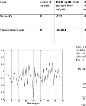
The well known matched filter response of Barker 13 has an PSLR of -22.289 dB but with the PSLR optimized filter lower PSLR is observed. The mismatched filter output from k=-12 to k=38 is plotted in Fig.1.1.As observed from the figure the peak of the filter output occurs at k=13.The matched filter output is not symmetric about k=M-N/2. The filter exhibits a LPG loss of -0.033dB and the PSLR obtained is -35.35 dB. The deviation of the mismatched filter weights from the matched filter weights are plotted in Fig.1.2.The population size chosen is 20 and the number of iterations is 200. Fig.1.3 indicates the mismatched filter output with a ternary chaotic code of length 21.The PSLR with matched filter was -22.3 dB. With mismatched filter PSLR as low as -26.17 dB is obtained as observed from the plot. But the LPG is -0.0361dB.The population size is 50 and the number of iterations is 200.
-20 -10 0 10 20 30 40
-70 -60 -50 -40 -30 -20 -10 0
12.9503
k
M
is
m
a
tc
h
fi
lt
e
r
ou
tpu
t
in
dB
-35.331dB
Fig 1.1 Mismatched filter output for Barker code
Table 1.1
PSLR of Barker code and chaotic binary code
0 5 10 15 20 25 30 35 40 -0.4
-0.3 -0.2 -0.1 0 0.1 0.2 0.3
filter weights
d
e
v
ia
ti
o
n
Fig.1.2 The mismatched filter elements deviation from Barker 13 signal values
-30 -20 -10 0 10 20 30 40 50 60 70 -70
-60 -50 -40 -30 -20 -10 0
K
m
is
m
a
tc
he
d
fi
lt
e
r
ou
tpu
t
in
dB -26.1710 dB
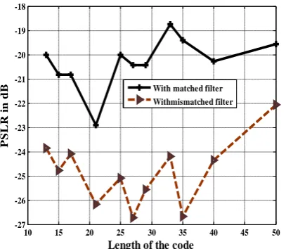
filter. The significant improvement in PSLR is observed from the table. To understand the reduction in PSLR very clearly, a plot of PSLR obtained with matched filter and with mismatched filter for ternary chaotic codes is also plotted in Fig 1.4
Table 1.2
PSLR of ternary chaotic codes from matched filter and
mismatched filter
Code Length of
the code
PSLR in dB (From matched filter output)
PSLR in dB
(From mismatched filter output)
LPG in dB
Barker13 13 -22.9 -35.3551 -0.0333
Chaotic binary code 25 -18.4164 -20.4688 -0.0838
Length of sequence
PSLR in dB (From matched filter o/p)
PSLR in dB (From mismatched filter o/p)
LPG in dB
13 -20 -23.8495 -0.323
15 -20.8279 -24.7694 -0.082
17 -20.8279 -24.0853 -0.064
21 -22.9 -26.1710 -0.036
25 -20 -25.0926 -0.140
27 -20.4238 -26.7177 -0.998
29 -20.4238 -25.5605 -0.067
33 -18.7570 -24.2012 -0.117
35 -19.4007 -26.6595 -0.393
[image:4.595.72.348.112.454.2] [image:4.595.67.275.499.698.2]10 15 20 25 30 35 40 45 50 -27
-26 -25 -24 -23 -22 -21 -20 -19 -18
Length of the code
P
S
L
R
i
n
d
[image:5.595.64.268.82.259.2]B With matched filter Withmismatched filter
Fig.1.4.Comparison plot of PSLR with matched filter and with mismatched filter for ternary chaotic codes
5. CONCLUSION
In this paper a new method of design of mismatched filter to optimize PSLR of binary and ternary codes is proposed .For the ternary chaotic codes, good improvement in PSLR is observed at lower lengths. The filter can be used for larger length sequences but the length of the filter also proportionally increases with the length of the sequence which may make the practical implementation of the filter difficult. The most significant reduction in PSLR obtained with ternary chaotic code is -26.1740 dB at length 27. Reduction in PSLR of the mismatched filter output of Barker code is also observed which is -35.3551 dB . In previous literature design of mismatched filters using evolutionary algorithms like particle swarm optimization has been reported. But, the advantage of DE algorithm over the other methods is that it presents simple structure, convergence speed, versatility and robustness. The performance of the classical DE is sensitive to the choice of control parameters including the design of mutation factor. So this work can be extended to obtain better results by using the other schemes of DE to sequences of any length.
6. REFERENCES
[1] Skonik,M.I.,Introduction to Radar Systems‘Tata McGraw Hill Book Co. ,New York,3rd Ed., 2001. [2] Levanon, N., Mozeson, E.,Radar Signals, Hoboken,
NJ:John Wiley & Sons, Inc.2004.
[3] Ackroyd,M.H.and Ghani.F ‗Optimum mismatched filters for sidelobe suppression ‗ IEEE Transactions on Aerospace and Electronic systems,Vol.9,pp. 214-218,March 1973.
[4] Zoraster,S.‘Minimum peak range sidelobe filter for binary phase coded waveforms,‘ IEEE Transactions on Aerospace and Electronic systems,Vol.16,pp.112-11 ,January 1980.
[5] Baden,J.M. and M.N Cohen‘ Optimum peak sidelobe filters for biphase pulse compression‘ Proceeding of the IEEE International radar Conference, pp-252-259, 1990
[6] Kwan,H.K., and Lee,C.K.,‘A neutral network approach to pulse radar detection‘ IEEE Trans. Aerosp. electron.Syst.,29, (1), pp. 9-21, 1993.
[7] Nunn, C. ‗Constrained optimization applied to pulse compression codes, and filters‘. IEEE Int. Radar Conf., pp.190–194,9–12 May 2005.
[8] Levanon,N. ‘Cross Correlation of long binary signals with long mismatched filters‘ IEE Proc.-Radar and Sonar navig., July 2005.
[9] Xin Wu, Weixian Liu, Lei Zhao, Jeffrey .S.Fu, ‗Chaotic Phase Code for Radar Pulse Compression‘. IEEE Radar Conf. 2001, pp. 27-28.
[10]Seventline,J.B., Elizabeth Rani, D.,Raja Rajeswari.K,‘Ternary Chaotic Pulse Compression Sequences‘ Journal of Radio Engineering, Vol.19,No:3, pp.415-420, September 2010.
[11]Storn, R., Price, K., ‗Differential evolution: a simple and Efficient Adaptive scheme for global optimization over continuous spaces‘ Technical Report , TR-95- 12, International Computer Science Institute, Berkeley, USA, 1995.
[12]Storn ,R.Price ,K.V.‘ Differential evolution – a simple and efficient heuristic for global optimization over continuous spaces.‘Journal of Global Optimization, Vol.11 pp.341- 359,1997.
Liu B, Wang .L., Jin ,Y.H., Huang, D.X, Tang F. ‗Control and Synchronization of chaotic systems by differential evolution algorithm‘ Chaos, Solitons & Fractals 34(2), Elsevier,pp.412–419,2007.
[13]Chang,W.D.‗Parameter identification of Rossler‘s chaotic system by an evolutionary algorithm‘, Chaos,Solitons& Fractals , Elsevier, pp.1047–53,2006.
[14]Leandrrodos Santos Coelho, Joao Guilherme Sauer and MarceloRudek ‗Differential evolution optimization combined with chaotic sequences for image contrast enhancement‘ Chaos, Solitons and Fractals, Elsevier, Volume 42 ,Issue 1, pp.522-529,October 2009
Swagatam Das, Ponnuthurai Nagaratnam Suganthan‘ Differential Evolution: A Survey of the State-of-the-Art‘ IEEE Transactions on Evolutionary Computation, Vol. 15, No. 1, pp.4-31,February 2011
[15]Vikas Baghel .‘Multiobjective Optimization — New Formulation and Application to Radar Signal Processing ‗M.Tech thesis,2009 .