A Novel RNS Overflow Detection and Correction
Algorithm for the Moduli Set
𝟐
𝒏
− 𝟏, 𝟐
𝒏
, 𝟐
𝒏
+ 𝟏
P. A. Agbedemnab and E.K. Bankas
Department of Computer Science, University for Development Studies,Navrongo, Ghana.
ABSTRACT
In this paper, an efficient scheme for detecting and correcting overflow during addition in Residue Number System (RNS) is presented. The approach which is novel to the moduli set 2𝑛− 1, 2𝑛, 2𝑛+ 1 is based on the Chinese Remainder Theorem and demonstrates theoretically to be a very fast scheme compared to similar state of the art schemes. The proposed method is able to detect overflow in RNS addition without full reverse conversion; Additionally, the scheme also prevents the representation of wrong numbers as a result of overflow, thus the scheme gives the accurate result without errors whether overflow occurs or not. A comparison, which proves the efficiency of the proposed scheme, in terms of delay and area requirements is also presented.
General Terms
Residue Number System, Circuits and Systems, Computer Arithmetic, Computer Architecture, Overflow, Digital Signal Processing.
Keywords
Residue Number System, Chinese Remainder Theorem, overflow detection, overflow correction, moduli set
2𝑛− 1, 2𝑛, 2𝑛+ 1 .
1.
INTRODUCTION
Residue Number System (RNS) is a non-weighted number system that utilizes remainders to represent numbers. This number system is capable of supporting parallel, carry-free and high speed arithmetic. The system is applied in the fields of Digital Signal Processing (DSP) intensive computations like digital filtering, convolutions, correlations, Discrete Fourier Transform (DFT) computations, Fast Fourier Transform (FFT) computations and direct digital frequency synthesis [1], [2], [3].
Nevertheless, operations such as division, overflow detection and correction, sign detection and magnitude comparison are problematic and very complex in RNS. In some cases, some of these operations, such as overflow and sign detection, are essential and cannot be avoided [4].
RNS is determined by a set S, of N integers that are pair-wise relatively prime. That is
𝑆 = {𝑚1, 𝑚2, … , 𝑚𝑁}
Where 𝑔𝑐𝑑 𝑚𝑖, 𝑚𝑗 = 1 for 𝑖, 𝑗 = 1, . . . , 𝑁 and 𝑖 ≠ 𝑗, and gcd means the greatest common divisor [8].
Every integer 𝑋 in [0, 𝑀 − 1] can be uniquely represented with a N-tuple where,
𝑀 = 𝑚𝑖 𝑁
𝑖=1
, 𝑋 → 𝑥1, 𝑥2, … , 𝑥𝑁
and 𝑥𝑖 = 𝑋 𝑚𝑖 = 𝑋 mod 𝑚𝑖 ; for 𝑖 = 1 𝑡𝑜 𝑁
The set S and the number 𝑥𝑖 are called the moduli set and residue of X modulo 𝑚𝑖 respectively.
Now, to calculate the number X from its residues, we can apply the CRT which is formulated as;
𝑋 = ℓ𝑖 𝑁
𝑖=1
𝑘𝑖𝑥𝑖 𝑚𝑖
𝑀
(𝟏)
where,
𝑀 = 𝑚𝑖 𝑁
𝑖=1
; ℓ𝑖= 𝑀
𝑚𝑖 ; 𝑘𝑖× ℓ𝑖 𝑚𝑖= 1
Overflow is a condition where a number which falls outside the legitimate range of a particular RNS i.e.,[0, 𝑀 − 1], (𝑀 = 𝑛𝑖=1𝑚𝑖) is well represented as a legitimate RNS number. During addition, this can be detected when the result of the addition is less than one of the addends. For example, given two RNS numbers 𝑋 and 𝑌 such that 𝑍 = 𝑋 + 𝑌 𝑚𝑜𝑑 𝑀 where 𝑋 ≥ 0 and 𝑌 < 𝑀, overflow will only occur when 𝑍 < 𝑋.
Another efficient way to detect overflow in RNS is via parity checking [1], [5]. It indicates whether an integer is even or odd. Suppose two integers (𝑋, 𝑌) have the same parity: 𝑍 = 𝑋 + 𝑌. An overflow occurs if Z is odd. Contrary, if (𝑋, 𝑌) have different parity, then an overflow occurs if Z is even. This technique is one of the best and fastest suggested methods to detect the overflow in RNS. However, this technique is only suitable for moduli sets with odd dynamic range (DR). But RNS systems that have even DR have more attractive features than those with odd DR. This is because using (2𝑛) modulo which tends dynamic ranges to even, greatly simplifies and reduces the delay and complexity of the scheme [4]. Thus the need to devise techniques of detecting overflow in moduli sets with even dynamic range.
is a very fast scheme compared to best known similar state of the art designs.
The rest of the paper is organized as follows: Section 2 presents the proposed method. In Section 3, the hardware implementation of the proposed scheme is presented, a simplified algorithm with numerical examples are also presented. The performance of the proposed scheme is evaluated in Section 4 whiles the paper is concluded in Section 5.
2.
PROPOSED METHOD
In this section, a new method for detecting overflow as well as preventing the representation of illegitimate numbers as if they are legitimate numbers in the DR (thus correcting overflow) is presented.
2.1
Algorithm for the Proposed Scheme
The algorithm for the proposed method is as follows; 1. Compute 𝜌𝑥 and 𝜌𝑦 according to (7)
2. Determine 𝐾 and 𝛽 according to (10) and (11) 3. Overflow occurs only under one of the following
conditions;
(i) If the MSB of 𝐾 i.e 𝐾2𝑛 = 1 (ii) If 𝐾2𝑛−1 down to 𝐾0 is “1”
(iii) If 𝐾2𝑛−1 down to 𝐾1 is “1” and 𝛽 = 1 4. The correct result is computing Z according to (10) Given the RNS numbers 𝑋 = 𝑥1, 𝑥2, 𝑥3 and
𝑌 = (𝑦1, 𝑦2, 𝑦3) with respect to the moduli set 2𝑛− 1, 2𝑛, 2𝑛+ 1 , where 𝑚1= 2𝑛− 1, 𝑚2= 2𝑛 and 𝑚3= 2𝑛+ 1 we have
ℓ1=2𝑛 2𝑛+ 1 ; ℓ2= 22𝑛− 1 ;
ℓ3=2𝑛 2𝑛− 1 (2)
Theorem 1: For the given moduli set, we have 𝑘1 𝑚1= 2𝑛−1𝑚1 (3)
𝑘2𝑚2= −1 𝑚2 (4)
𝑘3𝑚3= −2
𝑛−1
𝑚3 (5)
The proof of (3) – (5) is demonstrated in [9].
Theorem 2: For the given moduli set, any RNS number X can be represented as;
𝑋 = 2𝑛𝜌 + 𝑥
2 (6)
where,
𝜌 = 2𝑛𝑥1+ 𝑥1 2𝑛−122𝑛−1+ −2𝑛𝑥222𝑛−1 + −𝑥322𝑛−1+ +2𝑛−1𝑥3 22𝑛−1
22𝑛−1
(𝟕)
Proof: Substituting equations (2) through to (5) into (1) and factorizing out 2𝑛 we obtain (6).
From (6), let 𝑋 and 𝑌 be two RNS numbers such that their sum is 𝑍. Which implies from (6) that:
𝑋 = 2𝑛𝜌𝑥+ 𝑥2 (8)
𝑌 = 2𝑛𝜌𝑦+ 𝑦2 (9)
𝑍 = 2𝑛 𝜌
𝑥+ 𝜌𝑦 + 𝑥2+ 𝑦2
= 2𝑛𝐾 + 𝜇 (10) Where 𝐾 = 𝜌𝑥+ 𝜌𝑦and 𝜇 = 𝑥2+ 𝑦2
Let
𝛽 =
𝜇 < 2𝑛, 0
𝜇 ≥ 2𝑛, 1 (11)
Theorem 3: Given any two RNS numbers
𝑋 = 𝑥1, 𝑥2, 𝑥3 and 𝑌 = (𝑦1, 𝑦2, 𝑦3), overflow occurs if and only if
𝐾 ≥ 22𝑛− 1 (12)
or
𝐾 = 22𝑛− 2 and 𝛽 = 1 (13)
Proof: Assume (12) holds true; then for (10) 𝑍 ≥ 2𝑛 22𝑛− 1 + 𝜇 ≥ 𝑀 + 𝜇
Which is outside the legitimate range, i.e. [0, 𝑀 − 1], hence overflow will occur.
Furthermore, if (13) holds true then (10) can be rewritten as 𝑍 = 2𝑛 22𝑛− 2 + 1
= 𝑀,
which is also outside the legitimate range, therefore overflow will occur. Hence proofed.
From equation (10), 𝑍 will be the correct result of summing 𝑋 and 𝑌 whether overflow occurs or not in the given moduli set, but will be out of the range in [0, 𝑀 − 1] if either (12) or (13) holds; therefore 𝐾 should be added to the DR to be [0, 𝑀 + 𝐾 − 1] in order to legitimize 𝑍.
3.
HARDWARE IMPLEMENTATION
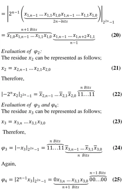
Equation (7) can further be simplified as follows 𝜌 = 𝜑1+ 𝜑2+ 𝜑3+ 𝜑422𝑛−1 (14) where
𝜑1= 2𝑛𝑥1+ 𝑥1 2𝑛−122𝑛−1 (15) 𝜑2= −2𝑛𝑥2 22𝑛−1 (16) 𝜑3= −𝑥322𝑛−1 (17) 𝜑4= 2𝑛−1𝑥3 22𝑛−1 (18)
Now, we consider (14)-(17) and simplify them for implementation in a VLSI system. It is necessary to note that 𝑥𝑖,𝑗 means the j-th bit of 𝑥𝑖.
Evaluation of 𝜑1
The residue 𝑥1 can be represented as follows; 𝑥1= 𝑥1,𝑛−1… 𝑥1,1𝑥1,0 (19)
Thus,
2𝑛𝑥1+ 𝑥1 2𝑛−1 22𝑛−1=
2𝑛−1 𝑥1,𝑛−1… 𝑥1,00. . .0 𝑛 𝐵𝑖𝑡𝑠
2𝑛−𝑏𝑖𝑡𝑠
+ 0. . .0 𝑛 𝐵𝑖𝑡𝑠
𝑥1,𝑛−1… 𝑥1,0
2𝑛
= 2𝑛−1 𝑥1,𝑛−1… 𝑥1,1𝑥1,0𝑥1,𝑛−1… 𝑥1,1𝑥1,0
2𝑛−𝑏𝑖𝑡𝑠
22𝑛−1
= 𝑥1,0𝑥1,𝑛−1 𝑛+1 𝐵𝑖𝑡𝑠… 𝑥1,1𝑥1,0𝑥1,𝑛−1 … 𝑥1,𝑛+2𝑥1,1 𝑛−1
(20)
Evaluation of 𝜑2:
The residue 𝑥2 can be represented as follows; 𝑥2= 𝑥2,𝑛−1… 𝑥2,1𝑥2,0 (21)
Therefore,
−2𝑛𝑥2
22𝑛−1= 𝑥2,𝑛−1… 𝑥2,1𝑥2,011. . .11
𝑛 𝐵𝑖𝑡𝑠
(22)
Evaluation of 𝜑3 and 𝜑4:
The residue 𝑥3 can be represented as follows; 𝑥3= 𝑥3,𝑛… 𝑥3,1𝑥3,0 (23) Therefore,
𝜑3= −𝑥3 22𝑛−1= 11. . .11
𝑛 𝐵𝑖𝑡𝑠
𝑥3,𝑛−1… 𝑥3,1𝑥3,0
𝑛 𝐵𝑖𝑡𝑠
(24)
Again,
𝜑4= 2𝑛−1𝑥3
22𝑛−1= 0𝑥3,𝑛 … 𝑥3,1𝑥3,0
𝑛+1 𝐵𝑖𝑡𝑠
00. . .00 𝑛−1 𝐵𝑖𝑡𝑠 (25)
Correction unit
In order to evaluate the sum Z, we further simplify equation (10).
𝑍 = 𝜏 + 𝜇 (26)
𝜏 = 2𝑛𝐾 = 𝐾
2𝑛𝐾2𝑛−1… 𝐾1𝐾000 … 0 𝑛 𝑏𝑖𝑡𝑠
3𝑛+1 𝑏𝑖𝑡𝑠
(27)
𝜇 = 𝜇 𝑛𝜇𝑛−1… 𝜇1𝜇0 𝑛+1 𝑏𝑖𝑠
(28)
Therefore,
𝑍 = 𝜏3𝑛𝜏3𝑛−1… 𝜏1𝜏0+ 00 … 0 2𝑛 𝑏𝑖𝑡𝑠
𝜇𝑛𝜇𝑛−1… 𝜇1𝜇0
3𝑛+1 𝑏𝑖𝑡𝑠
(29)
Implementation of equations (26) – (29) gives the correct result of 𝑍 whether overflow occurs or not.
3.1
Proposed Architecture
[image:3.595.52.253.64.376.2]ρ is computed according to equation (14) where all the parameters are defined in equations (15) – (18). For two numbers 𝑋 and 𝑌, 𝜌𝑥 and 𝜌𝑦 are the ρ values corresponding 𝑋 and 𝑌 respectively and are computed separately. As shown in Fig 1, ρ is computed using CSAs 1and 2 and two regular 2𝑛 -bit CPAs 1 and 2. The results of these CPAs are passed on to a multiplexer (MUX 1) which would then pass either of them down.MUX 1 will pass on the result of CPA 1 if the carry out of CSA 1 is a „0‟, otherwise the result of CPA 2 is passed on. 𝜌𝑥 corresponding to the binary number 𝑋 and 𝜌𝑦 corresponding to the binary number 𝑌 is added using a regular (2𝑛 + 1) 𝑏𝑖𝑡𝑠 CPA 3 in order to get 𝐾; at the same time, 𝑥2 and 𝑦2 is computed using a regular ( 𝑛 + 1) 𝑏𝑖𝑡𝑠 CPA 4 to obtain 𝜇. A multiplexer (Mux 2) is used to select the value of 𝛽 to be zero if the most significant bit (MSB) of 𝜇 is 0, otherwise, it selects one (1) if the MSB of 𝜇 is 1. This is shown in figure 2 which is the overflow detection unit. CSAs 1 and 2 require an area of 2𝑛∆𝐹𝐴 each as well as CPAs 1 and 2. Therefore, in order to obtain ρ will require a total area of 8𝑛∆𝐹𝐴. So for two numbers X and Y, the total area requirement will be 16𝑛∆𝐹𝐴.
CPA 3 demands an area of (2𝑛 + 1)∆𝐹𝐴 and CPA 4 also requires (𝑛 + 1)∆𝐹𝐴 of resources. Thus, the area requirement for the overflow detection component is (3𝑛 + 2)∆𝐹𝐴. Therefore, the total area requirement of the overflow detection scheme is (19𝑛 + 2)∆𝐹𝐴.
Regarding the delay, each CSA (i.e. CSAs 1 and 2) impose a delay of 𝐷𝐹𝐴 while the CPA pair 1 and 2 impose a delay of 2𝑛𝐷𝐹𝐴 since they are in parallel, for two numbers this will become 4𝑛𝐷𝐹𝐴, thus delay imposed on computing ρ is (4𝑛 + 2)𝐷𝐹𝐴. Also the CPA pair 3 and 4 impose a delay of (2𝑛 + 1)𝐷𝐹𝐴for the overflow detection unit. Therefore, the delay required for the proposed scheme is (6𝑛 + 3)𝐷𝐹𝐴. The correction unit uses a regular (3𝑛 + 1) 𝑏𝑖𝑡𝑠 CPA 5. The area requirement is (3𝑛 + 1)∆𝐹𝐴 and its delay is also (3𝑛 +
1)𝐷𝐹𝐴.
The schematic diagrams for the proposed scheme are shown below.
2𝑛 𝐵𝑖𝑡𝑠 CSA 1
2𝑛 𝐵𝑖𝑡𝑠 CSA 2
2𝑛 𝐵𝑖𝑡𝑠 CPA 1
𝑥1 𝑥2 𝑥3
Operands Preparation (OPPR)
𝑐1
𝜑1 𝜑2 𝜑3 𝜑4
𝑠1
𝑐2 𝑠2
2𝑛 𝐵𝑖𝑡𝑠 CPA 2
0
MUX 1
0 1
1
𝜌
2𝑛 + 1 𝐵𝑖𝑡𝑠
CPA 3
𝜌𝑦 𝜌𝑥
𝑛 + 1 𝐵𝑖𝑡𝑠CPA 4 𝑦2 𝑥2
MSB(𝜇) 𝜇
sel
0 1
[image:3.595.51.251.415.538.2] [image:3.595.311.562.526.757.2]𝛽
Fig 2: Overflow detection unit
3𝑛 + 1 𝐵𝑖𝑡𝑠 CPA 5
𝜇
𝜏
𝑍
[image:3.595.53.266.574.769.2]3.2
Numerical Illustrations
Let us now look at numerical examples with the proposed scheme.
Checking overflow in the sum of 49 and 21 using RNS moduli set {3, 4, 5}
49 = (1,1,4)𝑅𝑁𝑆 3 4 5 = 01,01,100 𝑅𝑁𝑆 11|100|101 21 = (0,1,1)𝑅𝑁𝑆 3 4 5 = 00,01,001 𝑅𝑁𝑆 11|100|101
= 01,01,100 + 00,01,001 𝑅𝑁𝑆 11|100|101 = 01,10,000 𝑅𝑁𝑆 11|100|101
RNS to decimal conversion of 01,10,000 𝑅𝑁𝑆 11|100|101 will result in the decimal number 10. Whilst the sum of the decimal numbers 49 and 21 is 70 which is obvious of overflow occurring.
Checking for RNS overflow using the proposed algorithm 𝜌𝑥= 12 = 01100
𝜌𝑦 = 5 = 00101
𝐾 = 𝜌𝑥+ 𝜌𝑦 = 01100 + 00101 = 10001 𝜇 = 01 + 01 = 010, 𝛽 = 0
Since the MSB of 𝐾 is “1”, the scheme will detect that overflow has occurred.
From (27),
𝑍 = 1000100 + 0000010 = 1000110 = (70)decimal
Checking overflow in the sum of 28 and 32 using RNS moduli set {3, 4, 5}
28 = (1,0,3)𝑅𝑁𝑆 3 4 5 = 01,00,011 𝑅𝑁𝑆 11|100|101
32 = (2,0,2)𝑅𝑁𝑆 3 4 5 = 10,00,010 𝑅𝑁𝑆 11|100|101
= 01,00,011 + 10,00,010 𝑅𝑁𝑆 11|100|101 = 00,00,000 𝑅𝑁𝑆 11|100|101
RNS to decimal conversion of 00,00,000 𝑅𝑁𝑆 11|100|101 will result in the decimal number 0. Whilst the sum of the decimal numbers 28 and 32 is 60, a clear sign of overflow occurring.
Checking for RNS overflow using the proposed algorithm 𝜌𝑥= 7 = 00111
𝜌𝑦 = 8 = 01000
𝐾 = 𝜌𝑥+ 𝜌𝑦 = 00111 + 01000 = 01111 𝜇 = 00 + 00 = 000, 𝛽 = 0.
Even though, the MSB of 𝐾 is not “1”, all other bits are “1” therefore the scheme will detect that overflow has occurred. From (27),
𝑍 = 0111100 + 0000000 = 0111100 = (60)decimal
Checking overflow in the sum of 10 and 11 using RNS moduli set {3, 4, 5}
10 = (1,2,0)𝑅𝑁𝑆 3 4 5 = 01,10,000 𝑅𝑁𝑆 11|100|101 11 = (2,3,1)𝑅𝑁𝑆 3 4 5 = 10,11,001 𝑅𝑁𝑆 11|100|101
= 01,10,000 + 10,11,001 𝑅𝑁𝑆 11|100|101 = 00,01,001 𝑅𝑁𝑆 11|100|101
RNS to decimal conversion of 00,01,001 𝑅𝑁𝑆 11|100|101 will result in the decimal number 21 which is correct result of 10 + 11.
Checking for RNS overflow using the proposed algorithm 𝜌𝑥= 2 = 00010
𝜌𝑦= 2 = 00010
𝐾 = 00010 + 00010 = 00100 𝜇 = 10 + 11 = 101, 𝛽 = 1.
After processing, the scheme will obviously detect no overflow since it is only 𝐾2𝑛−2= 1.
And from (27),
𝑍 = 0010000 + 0000101 = 0010101 = (21)decimal
4.
PERFORMANCE EVALUATION
In order to evaluate the performance of the proposed overflow detection scheme, it is compared with similar best known state of the art schemes.
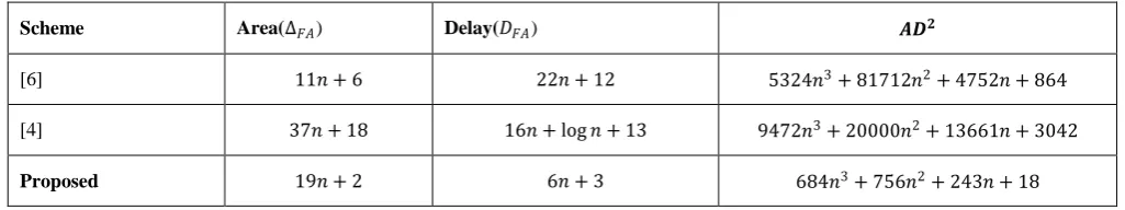
Theoretical analysis from Table 1 shows that the proposed scheme has less delay and complexity without compromising on accuracy compared to [4] which is the current best state of the art and has a correction component. The proposed scheme is also faster than [6] which was the best state of the art before [4]. Even though, the hardware complexity of the proposed scheme is higher than that in [6], the proposed scheme uses three comparators and a single AND gate whilst [6] uses six comparators and three AND gates which are not included in the comparison. It is also clear from the 𝐴𝐷2 analysis that the proposed scheme is very efficient than the state of the art schemes.
The correction part is not included in the evaluation just as it is not included in [4] for fairness. In any case, the accurate result is a 3𝑛 + 1 𝑏𝑖𝑡 sum (Z) in (10) therefore, a 3𝑛 + 1 𝑏𝑖𝑡 adder is designed to cater for the addition.
5.
CONCLUSION
Detecting overflow is one of the most important and complex operations in RNS. In this paper, a novel method for detecting and correcting overflow during addition is presented. The proposed technique does not require full RNS-binary conversion. The proposed scheme is able to give the correct result for the sum of two numbers whether overflow occurs or not. The proposed scheme is demonstrated theoretically to be very efficient than similar state of the art designs. Since only theoretical analysis was presented, our next focus will be to implement the proposed method using VHDL in Xilinx.
6.
REFERENCES
[1] A. Omondi and B. Premkumar. Residue Number Systems: Theory and Implementation. Imperial College Press. UK 2007.
[3] K.A. Gbolagade, R. Chaves, L. Sousa, and S.D. Cotofana. An improved reverse converter for the 22n+1− 1, 2n, 2n− 1 moduli set. IEEE International Symposium on Circuits and Systems (ISCAS 2010) , pp. 2103-2106, Paris, France, June,2010.
[4] D. Younes and P. Steffan. Universal approaches for overflow and sign detection in residue number system based on {2n− 1, 2n, 2n+ 1}. The Eighth International Conference on Systems (ICONS 2013), pp. 77 – 84, 2013.
[5] M. Rouhifar, M. Hosseinzadeh, S. Bahanfar and M. Teshnehlab. Fast Overflow Detection in Moduli set 2n− 1, 2n, 2n+ 1 . International Journal of Computer Science Issues, Vol (8/3), pp 407-414, May 2011. [6] H. Siewobr and K. A. Gbolagade. RNS Overflow
Detection by Operands Examination. International
Journal of Computer Applications (0975 – 8887), Vol 85, No. 18, January, 2014.
[7] M. Hosseinzadeh, A.S. Molahosseini and K. Navi. A parallel Implementation of the Reverse Converter for the moduli set 2n− 1, 2n, 2n−1− 1 . World Academy of Science, Engineering and Technology, Vol. 55, pp. 494-498. 2009.
[8] A. S. Molahosseini, K. Navi. New Arithmetic residue to binary Converters. International Journal of Computer Sciences and Engineering Systems, Vol. 1, No.4, pp. 295-299 Oct., 2007.
[image:5.595.45.558.278.374.2][9] E. K. Bankas and K. A. Gbolagade. A New Efficient FPGA Design of Residue-To-Binary Converter. International Journal of VLSI design & Communication Systems (VLSICS), Vol 4, No. 6, December, 2013.
Table 1: Area,Delay Comparison
Scheme Area(∆𝐹𝐴) Delay(𝐷𝐹𝐴) 𝑨𝑫𝟐
[6] 11𝑛 + 6 22𝑛 + 12 5324𝑛3+ 81712𝑛2+ 4752𝑛 + 864
[4] 37𝑛 + 18 16𝑛 + log 𝑛 + 13 9472𝑛3+ 20000𝑛2+ 13661𝑛 + 3042