Formal Conceptual Framework for Structure of Context
of Component-based System for Designing Robust
Software Systems and Metrics
Meenakshi Sridhar
Department of Computer Science and Applications,
M. D. University, Rohtak-124001, Haryana (India).
Nasib Singh Gill
Department of Computer Science and Applications,
M. D. University, Rohtak-124001, Haryana (India).
ABSTRACT
For defining a set of unambiguous and language-independent metrics and other relevant concepts, the need for definition of a formal conceptual framework of the context/environment, particularly for safety-critical environments, has earlier been recognized and emphasized. In this paper, a formal conceptual framework is proposed for defining metrics and other relevant concepts for a component-based system, in which, instead of
component, assembly—a slightly modified and more general
concept—is taken as a basic building block for design and development of software. The paper discusses a formal conceptual framework for the structure of context for a component-based system. In another paper, a formal conceptual framework for the dynamics/ behaviour within the context of a component-based system is discussed.
General Terms
Component-based Software Engineering (CBSE), Formal Methods in Software Engineering.
Keywords
Component, Assembly, Formal Conceptual Framework.
1.
INTRODUCTION
The advantages of using measurements/ metrics in software development are well-known and need not be recalled here. However, the need for formal, precise and complete definitions for metrics is not so well publicised. There is possibility of harmful consequences if metrics are expressed only informally [1, 2, 3].
In respect of formalization of definitions of metrics so as to overcome problems due to informal, imprecise or incomplete definitions of metrics; some important approaches and methods are proposed in [1, 4, 5, 6, 7, 8, 9, 10]. These contributions contain essential ideas for developing a
standardised formal conceptual framework of the problem domain under consideration, which can be used for defining measurements/ metrics—for both object-oriented as well as for component-based systems—so that all measures/metrics based on the framework be expressed in a fully consistent, non-redundant, unambiguous and fully operational manner. The contributions are based on the implicit assumptions that (i) the problem domain is part of a perfect world (i.e. it is a deterministic, static etc world) and that (ii) knowledge of the problem domain possessed by the system is also perfect (i.e. system’s knowledge of the problem domain is precise, complete, consistent, monotonic, factual, with agents having single shareable intelligence etc.).
On the basis of the seminal ideas used in these papers, a formal conceptual framework for the structure of context of a
component-based system is proposed here. In another paper, a formal conceptual framework for the dynamics within context of a component-based system is discussed. The approach followed is essentially the one proposed in [1]. The reason for choosing the approach as the basis of the work is that even by starting with a model based on assumptions of a perfect world with a perfect view of it, more realistic models and robust solutions can gradually be developed by incorporating both imperfections (e.g. randomness) of problem domain and of its knowledge (e.g. incompleteness/impreciseness). It can also be extended when the problem domain is dynamic and /or involves multi-agents. Another advantage of the approach is scalability—it allows easy extension of the system when some atomic elements need to be considered later as composed also. For example, an employee of an organization may be initially considered as atomic, with some specific attributes. However, the same employee as a patient in the clinic of the organisation may have to be considered as a set of organs, each organ with its own attributes. The approach facilitates this type of extension of a system.
Next, the structure of the remainder of the paper is outlined. The next section entitled ‘Related Work’ briefly describes a cross-section of the relevant literature. Section 3, which is the core of the paper, contains the details of the proposed formal conceptual framework. Its five subsections contain the details respectively of (i) meta-model for set of system entities (ii) mathematical specification of system entities (iii) mathematical specification of properties of system entities (iv) mathematical specification of relations between system entities, and (v) definitions & mathematical specification of properties of relations between system entities. Finally, the Section 4 concludes the presented work.
2. RELATED WORK
The reviewed literature covers issues, including foundational ones, related to various aspects of formalization of specification, design and measurement of software for different types of environments and for providing different types of services. The review includes outline—given below in chronological order—of the essential ideas involved/proposed in each of the contributions mentioned earlier, and additionally, in [11, 12, 13, 14, 15, 16]
In [12] a general framework is proposed for formalizing a subset of UML diagrams in terms of different formal languages based on a homomorphic mapping between meta-models describing UML and the formal language. The framework—proposed in order to overcome the difficulty because of the fact that UML comprises several different notations with no formal semantics attached to the individual diagrams—enables the construction of a consistent set of rules for transforming UML models into specifications in the formal language. Further, the paper describes the use of this framework for formalizing UML to model and analyze embedded systems.
[7] discusses problems arising out of, on one hand, the use of some natural language in defining software metrics, and on the other hand, problems arising out of the exclusive use of some formal language for the purpose. In this respect, they propose an approach for formal definitions ofobject-oriented (O-O) metrics based upon the UML meta-model. The approach allows unambiguous metrics definitions, which in turn help in increasing tool support for O-O metrics, and also for establishing comparisons among sets of metrics.
According to the abstract of the paper, in [8] a technique is described for formalizing metrics, built upon the UML 2.0 meta-model and using OCL as a metrics definition language for COTS-based architectures. As a proof of the concept, an example based upon a set of reusability metrics for fine-grained JavaBeans components is presented. Further, [9, 10] give formal and executable definitions respectively (i) of metrics to assess quality attributes of CORBA components and assemblies and (ii) of composition assessment metrics for CBSE, using an extension of the CORBA Component Model meta-model as the ontology for describing component assemblies. The definitions allow for independent scrutiny of such metrics, essential to increase practitioners’ confidence on predictable quality attributes.
In [13] is proposed a formal mathematical model covering design artefacts in service-oriented (SO) systems and their structural and behavioural properties. The model is proposed in view of the fact that there is no precise formal definition of what constitutes a Service-Oriented system, and also the design principles of Service-Oriented Computing are not well understood. This model is expected to promote a better understanding of SO concepts, and in particular, it may enable the definition of structural software metrics in an unambiguous and formal manner.
In [16] Service Dynamic Description Logic (SDDL) is proposed for representing and modelling the dynamic aspects of web services. Representation of the dynamic aspects in web services is no less important than the representation of static information. In this respect, the authors have introduced three basic reasoning services in the proposed formal framework to support the discovery and composition of web services.
According to the provided abstract, [15] describes the state of the art in the industrial use of formal methods, concentrating on their increasing use at the earlier stages of specification and design. Based on this, the authors discuss the issues surrounding the industrial adoption of formal methods. Finally, from futuristic point of view, they describe the development of a Verified Software Repository, part of the worldwide Verified Software Initiative.
In [1] is defined a conceptual framework—based on the formalism of algebraic sets and relations—for defining
concepts including those for metrics for component-based systems. The metrics so defined are unambiguous, straightforward and language independent.
According to the provided abstract, in [14] a formal framework for component based embedded systems is proposed. Resorting to such a framework, the soundness, congruence and completeness of system structures and behaviours can be derived. The framework involves various Models of Computation (MoC) reflecting interacting rules and operational semantics for system behaviours and a formal language specifying definitions, axioms, transition rules or equations/inequations for MoC as a meta-model. The formal language is composed of extended process algebra (EPA) and ordinary differential equations (ODE), both concerning discrete time and continuous time behaviours.
In [11] attention is drawn to the problems arising out of a large number of component models having been developed over the past decade, with many similarities but with many principle differences and unclear concepts. In order to overcome the problem, they discuss and characterize some fundamental principles for framing component models and provide a Component Model Classification Framework based on these principles. Further, using the framework they classify a number of component models.
Also, [17, 18, 19, 20, 21, 22, 23] contain many important ideas relevant to developing of formalized frameworks for component-based systems.
3. CONCEPTUAL FRAMEWORKS
The reported work is an extension—in respect of formally defining metrics for component-based systems—of some of the contributions mentioned in the previous section. A meta-model of the context for component-based systems is proposed in which (i) assembly (to be defined) instead of component, is taken as basic unit for the definition of the framework and in which (ii) the properties of relations among components/ assemblies, are formally defined, in addition to formally defining entities of the context, their properties, and relations between them.
Instead of the set of components, it is proposed to take fundamental/foundational set as SA, the set of Assemblies—
which initially consists of the available components or some subset of it from which the (complete) software is expected to be developed—to provide all the services required to be provided. An assembly is a software entity, which may not be a component ( i.e. it is not necessary that it conforms to the component model considered for the purpose), but, which may be obtained through composition which uses information only about provided and received interfaces(e.g. horizontal or partial vertical composition). The composition process initially starts only with some of the given components, and later uses recursively assemblies and components so obtained so as to finally yield required software [11].
obtained, and (ii) converting, through adaptation/customization, the assembly into a component according to the considered component model and fitting the requirement of the required software S. However, after the first mega-step, it may be found that either (i) currently the assembly may not lead to the required software, but later it may or (ii) there is another assembly, already obtained, which has better evaluation than the currently obtained assembly in respect of obtaining the required software S. Then, instead of discarding such an assembly, and treating the effort invested in it as wasted, the assembly so obtained is stored. Later on, after some cycles of development, if an earlier developed assembly may be found useful, then at that stage, the second mega-step of converting the assembly into a component may be applied. Similar approach is also suggested in [21]. In order to formally represent the structure of the problem domain, four types of sets for the meta-model are defined, viz. (a) set of entities (in this case, assemblies etc.), (b) set of properties of entities, (c) set of relations between entities and (d) set of properties of relations between system entities. Further, in order to represent in the meta model, the
dynamics/behaviour of the problem domain, one need to also include some mathematical entities to represent various
operations like composition of two components/ assemblies to get a new component/assembly, or to represent operations for adding or deleting interfaces from a component or a set of components to get the set of interfaces of a new component/ assembly. The matter relating to mathematical modelling of various operations like composition have been discussed in another paper.
Next, the task of formally defining the meta-model, for the structure of the context of the system under consideration, is initiated with the following semi-formal(partly expressed in natural language) definition.
3.1 A Meta Model for Set of System Entities
(SSE)
Definition 1: (A meta-model for the Structure of Set of
System Entities) The 4-tuple
(E, Prop (E), Rel (E), Rel-prop (E)) is called a structural meta-model for Set of System Entities (SSE), where
a. E represents the set of system entities (in this work, an entity ai is an assembly or a component);
b. Prop (E) denotes the set of the properties of the elements from E;
c. Rel (E) denotes the set of relations between the entities constructed out of elements of E, and
d. Rel-prop (E) denotes the set of properties of the relations between the entities constructed out of elements of E. In the ensuing sections, the semi-formal definitions given above of E, Prop (E), Rel (E), Rel-prop (E)are formalized in terms of mathematical concepts of set and relation.
For the definition of the meta-model, it is assumed that a software system S is required to be developed to provide all the services from the set, say, Serv, of services. Further, for this purpose, it is also assumed that initially a set of components, say CR, is given. And further, on the basis of judgement, a subset Comp (S) of CR, is selected to develop the required software S.
As a first step for formalization, an identifier need to be associated with each of the entities, property of an entity,
relation between any two entities and property of a relation etc., and also, to each of the sets, which may be required in the discussion of these entities, of relations and of properties. LetSi, i=1 to n, be the identifiers associated with required services, and let Cj, j= 1 to m, be the identifiers associated with the initially provided components. Then, formally,
Serv = {S1,S2, …., Si, …., Sn} ; CR = {C1, C2, ….., Cj, ….., Cm} In view of the fact that, the proposed meta model can be further extended to include formal conceptual framework of the behaviour/ dynamics of the problem domain through various operations on the underlying set CR., which then evolves into larger sets, and finally into the required software S; the set SA, of assemblies is considered, that represents the evolving (dynamically changing) set, the initial value of which is CR. However, a member of SA may be restricted to be a component only, where it is either an initially given component or is obtained by composing two members of SA.
Also, let Assemb (S), the initial value of which is taken as
Comp (S), denote the set of selected assemblies at a particular point of time, to construct the required software S. Each of the sets to be defined below evolves as SA evolves.
3.2 Mathematical Specification of System
Entities
An assembly can be defined in terms of its provided interfaces (functionalities, services), its required interfaces (contexts) and the dependencies between the two types of interfaces. For the purpose of formalization, let
pia,k , k = 1 to p and ria,l , l = 1 to q respectively denote identifiers associated with provided interfaces of assembly a, and required interfaces of assembly a. Then, PIa, the set of provided interfaces of assembly a, can be formally expressed as PIa = {pia,l, pia,2, .., pia,k, .., pia, p}, and RIa, the set of required interfaces of assembly a can be formally expressed as
RIa ={ria,1, ria,2, .., ria,l, .., ria,q}. By taking unions of the sets
PIa for a ∈ SA, onecan formally define the set of all provided interfaces of SA, which may be denoted by PI(SA). Similarly, the set of all required interfaces, to be denoted by RI(SA), can be formally defined. The set union of the PI(SA) and RI(SA)
formally defines the set of all interfaces of SA, and will be denoted as I(SA). Similarly, PI(Serv), RI(Serv) and I(Serv), respectively denoting the set of all interfaces provided by
Serv, the set of all interfaces required by Serv and the set of all interfaces of Serv can be formally defined.
Further, each interface of an assembly, component or service, is specified by its parameters. Let pa, i, i = 1 to r be the identifiers associated with assembly/component/service a.
Then, set of all parameters of a, denoted by Parama, is formally specified as Parama = {pa, 1, pa, 2, …, pa, i , …, pa, r}. By taking set union of appropriate Parama’s, each of
Param (SA), the set of all parameters of SA; and
Param (Serv), the set of all parameters of Serv, can also be formally defined.
Based on the above definitions and notations, the set of system entities is formally defined as in Equation (1) below:
E = SA ∪ Serv ∪ I(SA)∪ I(Serv) ∪ Param (SA) ∪ Param (Serv).…(1) In addition to the sets included in E, some other (auxiliary) sets will also be used for defining or explaining the involved ideas. Two of such sets are
(i) Types, which in the current context may be taken as
Types = {A, I, P}, where A denotes type of an element of
I (Serv), and P denotes type of an element of
Param (SA),or of Param (Serv). Types may be modified after taking into consideration future developments in CBSE.
(ii) Val (E), denoting the set of all values that may be associated with a property of an assembly, interface or parameter in E. The set Val (E) can only be decided and computed during the actual process of developing software using component-based approach (CBSE). During the discussion of mathematical specification of properties of system entities, the method of calculating
Val (E) will be discussed.
Through equation (1) above, the first element of 4-tuple
meta-model (E, Prop (E), Rel (E), Rel-prop (E)) is formally defined. Next, the second element Prop (E) of the meta-model is described in mathematical terms.
3.3 Mathematical Specification of
Properties of System Entities
In view of the fact—that the properties of three types of an element belonging to either of sets
SA, Serv, I (SA), I (Serv), Param (SA) and Param (Serv), though may not be identical yet are similar, and some properties are common to all three types—first, the mathematical specification of these common properties for a generic type T, is discussed, where, T may denote, at one time, either set SA(or set Serv), set I (SA)(or set I(Serv)), or set (or set Param(Serv)). Then, mathematical specification of each of the three types is discussed individually.
In this connection, it may be noted that for all elements of a particular type of entities, the properties are the same; whereas, for two elements of different types, properties may be different.
For the purpose of discussion of mathematical specification of the properties of the generic type T, let
EnT denote the set of entities of type T with EnT = {eT1, eT2, …, eTj, .... ,eTtn }, where tn is the number of entities in the set EnT.
PEnT denote the ordered set of properties of elements of
EnT with PEnT = (PT1, PT2, …, PTi, …., PTtm), where tm is the number of properties of any entity in EnT.
V-PEnT (i) denote the set of values of PropertyPTi, 𝑓𝑜𝑟 𝑖 = 1, 2, … . , 𝑡𝑚, where
V-PEnT (i) = { vi1, vi2, … , vik, … , vi ni}, and ni is the number of values of property PTi. Then
V-PEnT, the set of values associated with all properties of an entity of Type T, is given by the equation:
V-PEnT = ∪ V-PEnT (i), where union is taken over properties PTi, i= 1 to tm, of an entity T
For the purpose of defining Val (E), the set of all possible
values of properties of elements in E, let V-PEnT be
denoted as
V-PEn(T), in which T is explicitly taken as parameter. Then Val (E) =∪ V-PEn (T) , where union is taken over all types T of elements of E
At any point of time, to each entity eTj and property PTi, a unique value vik is associated, for some k= 1, 2, … , ni. This may be mathematically specified as: value ( eTj, PTi) = vik . It may be further expressed as the function
Fun-Pro-Val-T-i: EnT V-PEnT (i), for property PTi, for all i’s . This may be further generalized to the function
Fun-Pro-Val-T: EnT V-PEnT (1) × V-PEnT (2) × …… × V-PEnT (m) = (let) Ordered-V-PEnT
In the above, for simplification of notation, the type name T is used as suffix of various names such as
EnT, PEnT, V-PEnT etc. However, T is to be used as parameter in the further discussion, therefore, instead of
EnT, PEnT, V-PEnT (i), V-PEnT, Ordered-V-PEnT and Fun-Pro-Val-T, the notations respectively En (T), PEn (T), V-PEn (T, i), V-PEn (T), Ordered-V-PEn (T) and Fun-Pro-Val (T), will be used.
Definition 2 The 5-tuple given by Equation (2) below
Prop-Specification (T) =
[T, En (T), PEn (T), V-PEn (T), Fun-Pro-Val (T)] .…(2)
is called a properties-specification corresponding to type T. By varying 𝑇, En (T), PEn (T), V-PEn (T) and
Fun-Pro-Val (T), different specifications for type T are obtained.
Next, property specification of each of the individual type of entities, viz. SA (or set Serv), set I (SA) (or set I(Serv)), or set
Param (SA) (or set Param(Serv)), is discussed, which respectively denote Set of assemblies, Set of Interfaces of assemblies and Set of parameters of interfaces of assemblies. Let A, I and P denote abbreviated names respectively of the types SA, I(SA) and Param(SA).
It may be noted that Prop-Specification given below for each type is merely an illustration and that it is not exact and complete. Rather, it cannot be exact and complete in view of the facts that attributes/ qualities of each of assemblies, interfaces and parameters cannot be fixed in advance as these heavily depend on the specific requirement and usage context. Therefore, the exact and complete specification of attributes of each of these is determined by the team of designers and potential users of the system as per requirements and context. Also, it may be noted that non-functional attributes, and particularly the quality attributes like reliability, reusability, performance and security etc. are not of ‘all-or-none’ or
‘true-or-false’ type, rather these attributes can be specified only imprecisely. Hence these attributes are better modelled by Fuzzy Theory. The issues related to imprecision of quality attributes will be discussed and modelled in some later communication.
In the light of the above discussion, description of the
Prop-specification for various entities, beginning with the type Set of Assemblies, is given below.
Definition 3Prop-specification for entity type Set of Assemblies: The 5-tuple
Prop-Specification (A) = [A, SA, PEn (A), V-PEn (A), Fun-Pro-Val (A)]
is called specification of properties for entities of type Set of Assemblies, where
𝑃𝐸𝑛 (𝐴) = {CMM-Level-of-Vendor, Cost, Version, Percentage-as-required-software,Component-model,...};
V-PEn (A) (for simplicity, instead V-PEn-A is used ) is specified by the following equations
{Initial, Managed, Defined, Optimized, Quantitatively}
o V-PEn-A ( Cost) = [Lowest, Highest], range of cost values ;
o V-PEn-A (Version) = {Vi: i = 1,2, …, n}, where n is the number of the last version
o V-PEn-A (percentage-as-required-software) =
[0,100], any real number between 0 and 100; o V-PEn-A (component model) =
{DCOM, CORBA, EJB}
Fun-Pro-Val (A) (for simplicity, instead Fun-Pro-Val-A is used), is specified, for each particular instance, e.g. o Fun-Pro-Val-A ( (CMM-Level-of-Vendor) =
Quantitatively;
o Fun-Pro-Val-A (Cost) =
$ 20 million, Lowest
≤
$ 20 million ≤ Highesto Fun-Pro-Val-A ( Version) = V3, where 3 ≤ n o Fun-Pro-Val-A (percentage-as-required-software)
= 34
o Fun-Pro-Val-A (component model) = CORBA (the values on R.H.S’s are only as illustrations)
Other data, e.g. in respect of environment in which the assemblies are used, can be added later on during the design process. As is mentioned earlier, and as is exhibited by the above illustration, one of the advantages of this model is that it has the scalability property.
Next, the Property specification for the entity type Set of Interfaces is discussed.
Definition 4Prop-specification for entity type Set of Interfaces: The 5-tuple,
Prop-Specification (I) = [I, I (SA), PEn (I), V-PEn (I), Fun-Pro-Val (I)],
is called specification of properties for entities of type Set of Assemblies, where
PEn (I) = {Kind, Functionality};
V-PEn (I) (for simplicity, instead V-PEn-I is used ) is specified by the next two equations
o V-PEn-I (Kind) = {operation, event}; o V-PEn-I (Functionality) =
{provided, required}.
Fun-Pro-Val (I) (for simplicity, instead Fun-Pro-Val-I is used) is specified, for each particular instance, e.g.
o Fun-Pro-Val-I (kind) = event;
o Fun-Pro-Val-I (Functionality) = provided
Next, the Property specification for the entity type Set of Parameters is discussed.
Definition 5Prop-specification for entity type Set of Parameters: The 5-tuple,
Prop-Specification (P) =
[P, Param (SA), PEn (P), V-PEn (P), Fun-Pro-Val (P)]
,
is called specification of properties for entities of type Set of Param (SA), where
PEn (P) = { Kind, Type, Aggregation, Access};
V-PEn-P (P) (for simplicity, instead V-PEn-P is used ) is specified by the next two equations
o V-PEn-P (Kind) =
{external, return-value, argument};
o V-PEn-P (Type) =
{predefined, user-defined, library};
o V-PEn-P (Aggregation) = {simple, array, file}; o V-PEn-P (Access) =
{read-only, write-only, read-write}.
Fun-Pro-Val-P (P) (for simplicity, instead Fun-Pro-Val-P is used) is specified, for each particular instance, e.g.
o Fun-Pro-Val-P (Kind) = argument; o Fun-Pro-Val-P (Type) = predefined; o Fun-Pro-Val-P (Aggregation) = file; o Fun-Pro-Val-P (Access) = write-only.
3.4 Mathematical Specification of Relations
between System Entities
Next, the third element Rel (E) of the proposed 4-tuple meta-model (E, Prop (E), Rel (E), Func (E), Rel-prop (E) ) is described in mathematical terms.
As mentioned earlier in respect of Prop-Specification, the description of specification of relations given below is also merely an illustration and that it is not exact and complete. Rather, it cannot be exact and complete in view of the various factors mentioned earlier. Therefore, the exact and complete specification of all the required and relevant relations can only be determined by the team of designers and potential users of the system as per requirements and context.
Next, formal specification of two types of relations, viz. (i) dependency relations and (ii) connection relations, is given in terms of mathematical terms. Main differences between the two types of relations are
(a) Dependency relations are discussed in terms of interfaces viz. r and p etc. , whereas, connection relationships are between assemblies/components viz. c and d,
(b) In the case of dependency relation, for a given interface
(c) Dependency relations can be determined independent of the development process, but connection relations are established only during the development process.
Definitions & Notations 6 (for dependency relations): (i) For a given assembly a ∈ SA, and for p ∈ PIa and r ∈ RIa,
the ordered pair (p, r) is called a dependency for the assembly a, if the provided interface p requires interface r from some other assembly for providing its service. (ii) Further, let DRa denote the relation from PIa to RIa, i.e.
DRa⊆ PIa × RIaand is defined as the set DRa =
{(p, r) ∈ PIa × RIa: (p, r) is a dependency for assembly a} As per convention, (p, r) ∈ DRa is also written as
p DRa r.
(iii) DR (SA) = ∪ DRa, is the set of all dependencies for the entity SA, where union is taken over all a ∈ SA
Remark: In respect of the above definitions, it is important to note that there may be interfaces in PIa without dependencies,
and hence may not appear in DRa or DR (SA). The service of
such an interface is the service that handles input data.
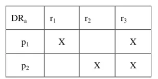
For each assembly a, the set of dependencies DRa, may be represented as a matrix/table. For example, PIa = {p1, p2} and
[image:6.595.90.245.388.465.2]RIa = {r1, r2, r3} with DRa = {(p1, r1), (p1, r3), (p2, r2), (p2, r3)} may be represented as the following table:
Table 1. Table representation of dependency relation
DRa r1 r2 r3
p1 X X
p2 X X
Next, connection relationship is discussed. In this regard, from earlier discussion, it may be recalled that
connection relationships are between assemblies/components viz. c and d,
connection relations are established only during the development process, and
for providing an interface say p by an assembly/component c, if an interface say r is required, then r may be provided by many assemblies/components
𝑑𝑖’𝑠. But, if a particular assembly/component, say, d3is selected and actually used for providing r, then, on this ground, c is in connection relationship with only d3, and not with
other 𝑑𝑖’𝑠.
Next, various types of connection relations between assemblies/components and sets of these relations, are formally defined.
Definitions & Notations 7 (for connection relations): i. Let c, d ∈ Assemb (S) and r∈ RIc, then assembly 𝑐 is
said to be in-connected-through-r-with-assembly d
within the system S, if r ∈ PId and 𝑐 uses the required interface 𝑟 from 𝑑. The relation is denoted by c In-connected-in-S (r, d). Also, the fact may be expressed as (c, (r, d)) ∈ In-connected-in-S.
Further,
In-connected-in-S
⊆ Assemb (S) × (RI (SA) × Assemb (S)) and
In-connected-in-S = {(c, (r, d)): c, d ∈ Assemb (S) and ∃ r ∈RI (SA) such that
c is in-connected-through-r-with-assembly d}.
ii. Let c, d ∈ Assemb (S), then c is said to be in-connected-to-assembly d within the system S, (this time r is not explicitly mentioned in the name of the relation) if there is an r∈RIcsuch thatr ∈PIdand c uses the required interface r from d. The relation is denoted as c In-connected-in-S-to-assembly d. Also, the fact may be stated as (c, d) ∈ In-connected-in-S-to-assembly.
Further,
In-connected-in-S-to-assembly ⊆ Assemb (S) × Assemb (S)
and In-connected-in-S-to-assembly =
{(c, d)): c, d ∈ Assemb (S) and ∃ r∈RI (SA) and c is in-connected-through -r-with-assembly d}.
iii. Let Set-in-connected-in-S-to-c = {(r,d): r ∈ RIc and d ∈
Assemb (S) and c in-connected-through-r-to-assembly d} be the set of all used in-connections of
c ∈ Assemb (S).
iv. Let c ∈ Assemb (S). For p ∈ PIc,
In-connected-in-S-to-c-for-provided (p) =
{(r, d): (r, d) ∈ Set-in-connected-in-S-to-c ∧ (p, r) ∈ DRc} , be the set of all in-connections of assembly c for the provided interface p.
v. Let c ∈ Assemb(S), for p ∈ PIc, then
Set-assembly-in-connected-in-S-to-c-for-provided (p) =
{d: for some r ∈ RIc: (r, d) ∈ Set-in-connected-in-S-to-c ∧ (p, r) ∈ DRc} , be the set of all in-connections-to-assembly of
assembly c for the provided interface p.
vi. Let c, d ∈ Assemb (S) and p ∈ PIc. Then assembly c is
said to be
out-connected-through-p-to-assembly d within the system S, if p ∈ RId and assembly d uses p from assembly c. The relation is denoted by
c Out-connected-in-S (p, d). Also, the fact may be expressed as (c, (p, d)) ∈ Out-connected-in-S
Further,
Out-connected-in-S ⊆ Assemb (S) × (PI (SA) ×Assemb(S))
and
Out-connected-in-S = {(c, (p, d)): c, d ∈ Assemb (S) and
∃ p ∈ PI (SA)
such that c is out-connected-through-p-to-assembly d} vii. Let c, d ∈ Assemb (S). Then assembly c is said to be
out-connected-to-assembly d within the system S, if there is a p ∈ PIc such that p ∈ RId and assembly d uses the required interface p from c. The relation is denoted as c Out-connected-in-S-to-assembly d. Also, the fact
may be stated as
(c, d) ∈ Out-connected-in-S-to-assembly.
Further,
Assemb (S)
and
Out-connected-in-S-to-assembly =
{(c, d)): c, d ∈ Assemb (S) and ∃ p ∈ PI (SA) and c is ou t-connected-through-p-to-assembly d}
viii. Let Set-out-connected-in-S-to-c =
{(p, d): p ∈ PIc and d ∈ Assemb (S) and c out-connected-through- p-to-assembly d} be the set of all out-connections of
c ∈ Assemb (S).
ix. Let c ∈ Assemb(S), for r ∈ RIc,
Out-connected-in-S-to-c-for-required (r) =
{(p, d): (p, d) ∈ Set-out-connected-in-S-to-c ∧ (p, r) ∈ DRc}, be the set of all out-connections of assembly c for the required interface r.
x. Let c ∈ Assemb(S), for r ∈ RIc, then
Set-assembly-Out-connected-in-S-to-c-for-required (r) =
{d: for some p ∈ PIc: (p, d) ∈ Set-out-connected-in-S-to-c
∧ (p, r) ∈ DRc}, be the set of all out-connections-to-assembly of out-connections-to-assembly c for the required interface r. The connection relationship may help in finding the optimal assembly/ component di, for a given assembly/component c, which contains maximum possible required interfaces for (i) a particular required interface value for c and/or (ii) all the required interfaces of component c. The above argument may be used for defining suitable metrics.
3.5 Definitions and Mathematical
Specification of Properties of Relations
between system Entities
For the purpose of discussion in this sub-section, the following formal definitions may be recalled that are used to specify a k-ary relation. In addition, as is the practice in RDBMS, tables are also used to specify a k-ary relation.
Definition 8 A k-ary relation𝐿 over the sets X1, … , Xk is a subset of their Cartesian product, written as
L ⊆ X1 × … × Xk. Further, if X1 = X2= … = Xi = … Xk,
then L is called a relation or k-ary relation in X1
Definition 9 In case k=2, generally, L is called a relation fromX1 to X2. As mentioned earlier, if X1 = X2, then L is called a relation in X1.
Definition 10 A k-ary relation L over the sets X1, … ,Xkis a (k + 1)-tuple L = (x1, …, xk, G(L)), where G(L) is a subset of the Cartesian productX1 × … × Xk. Then G (L) is called the graph of L.
Definition 11 A relation is said to be contained in (or is a sub-relation of) a relation S ⊆ 𝑋1 × … × 𝑋𝑘 , if R is a subset of S, that
(x1, x2, … xi, …, xk) ∈ Rimplies (x1, x2, … xi, …, xk)∈ S. Further, if R and S are not equal as sets, then R is also said to be strictly smaller than S. For example, as a relation on numbers ‘>’ is strictly smaller than ‘≥’.
Definition 12 In Database Systems, a k-ary relation is represented as an n×k matrix/table, where k is a constant natural number and n is a variable natural number.
Using these definitions, next, the properties of relations between system entities, are specified. In most of the discussion below, Definition 8 or Definition 9 will be used.
3.5.1 Mathematical Specification of Properties of
Relations
Set-of-relation-specification-methods =
{table, set-of-k-tuples, set-of-(k+1)-tuples, ……}; where the value ‘table’ is used when the relation is in context of Database Systems.
Set-of-relation-arities =
{unary, binary, ternary, quaternary}∪ {k-ary, with k being an integer ≥ 5}
Set-of-binary-relation-in-a-set-properties =
{transitive, reflexive, Irreflexive/ strict, coreflexive ,
symmetric , antisymmetric , asymmetric , transitive , total , trichotomous , equivalence, partial-order, total-order, well-order, 𝑖𝑛𝑗𝑒𝑐𝑡𝑖𝑣𝑒, 𝑠𝑢𝑟𝑗𝑒𝑐𝑡𝑖𝑣𝑒, functional,… } .
Each of the properties can be written in the form of a procedure.
Further, if a member of set-of-relation-specification-methods is ‘table’, i.e. when the relation is considered in context of Database Systems,
then set-of-relation-as-in-database-properties
= {1NF, 2NF, 3NF, BCNF, ….}.
Each of the properties can again be written in the form of a procedure.
4. CONCLUSION AND FUTURE WORK
In order to define unambiguous and language-independent concepts, including software metrics, for component-based software development; in this paper, a formal conceptual framework for the structure of the problem domain is defined, in which, instead of component, assembly—a slightly modified and more general concept—is taken as a basic building block for development of software. In another paper, a formal conceptual framework for the dynamics/behaviour
within the problem domain is defined. The advantage of the proposed framework is that it is more efficient than a framework in which ‘component’ is necessarily taken as building block. Another advantage of proposed framework is its scalability. The definition of the proposed framework is given under the assumption—common for most of the software development endeavours so far—that the problem domain and its knowledge, both are perfect. However, for developing realistic models and robust solutions, it is essential to take into consideration both imperfections of problem domains (e.g. inherent randomness of domain) and of its knowledge (e.g. incompleteness/impreciseness). The proposed framework can be easily extended to the cases when the problem domain is imperfect and/or knowledge of the problem domain is imperfect, thereby providing solid foundations for developing robust software.
5. ACKNOWLEDGEMENTS
6. REFERENCES
[1] C. Serban, A. Vescan and H. Pop, A Conceptual Framework for Component-based System Metric Definition,
9th RoEduNet IEEE International Conference 2010. [2] N. Gill, and P. Grover, Component-Based Measurement:
Few Useful Guidelines, ACM SIGSOFT Software engineering Notes, Vol. 28 Issue 6. November 2003. [3] N. Gill, Importance of Software Component
Characterization For Better Software Reusability, ACM SIGSOFT Software Engineering Notes Vol. 31 No. 1, January 2006.
[4] L. Briand, S. Morasca and V. Basili, Property-based Software Engineering Measurement, IEEE Transactions On Software Engineering, Vol. 22, No. 1, January 1996. [5] L. Briand, J. Daly and J. Wust, A Unified Framework for
Coupling Measurement in Object-Oriented Systems. IEEE Transactions on Software Engineering, 25(1), 91-121, 1999.
[6] R. Reiβing, Towards a model for object-oriented design measurement. Proceedings of ECOOP Workshop on Quantitative Approaches in Object Oriented Software Engineering, 2001.
[7] A. Baroni, S. Braz and F. Abreu, Using OCL to formalize object-oriented design metrics definitions. Proceedings of ECOOP Workshop on Quantitative Approaches in Object-Oriented Software Engineering, 2003.
[8] M. Goulão, F. Abreu, Formalizing metrics for COTS, Department of Informatics, Faculty of Sciences and Technology, New University of Lisbon,2825-114 Monte de Caparica, Portugal, 2005a.
[9] M. Goulão, and F. Abreu, Formal Definition of Metrics upon the CORBA Component Model. First International Conference on the Quality of Software Architectures (QoSA) 2005b.
[10]M. Goulão, and F. Abreu, Composition Assessment Metrics for CBSE. In Proceedings of the 31st Euromicro Conference - Component-Based Software Engineering Track. Porto, Portugal: IEEE Computer Society, 2005c. [11]Crnkovic, S. Sentilles, A. Vulgarakis, and M. Chaudron,
A Classification Framework for Software Component Models, IEEE Transactions On Software Engineering, Vol. 37, No. 5, September/October 2011.
[12]W. McUmber and B. Cheng, A General Framework for Formalizing UML with Formal Languages, Proc. of
IEEE International Conference on Software Engineering (ICSE01), May 2001, Toronto.
[13]M. Perepletchikov, C. Ryan, K. Frampton, and H. W. Schmidt, A Formal Model of Service-Oriented Design Structure, Proceedings of the Australian Software Engineering Conference (ASWEC'07), 2007.
[14]Y. Tu, D. Li, F. Li and S. Zheng, A Formal Framework for Component-Based Embedded System, 2010 IEEE/ASME International Conference on Advanced Intelligent Mechatronics, Montréal, Canada, July 6-9, 2010.
[15]J. Woodcock, P. Larsen, J. Bicarregui and J. Fitzgerald, Formal Methods: Practice and Experience, ACM Computing Surveys, Vol. 41, No. 4, Article 19, Publication date: October 2009.
[16]J. Zhixiong, L. Qian, and X. Pen, A Formal framework for description of semantic web services , Seventh International Conference on Computer and Information Technology 2007 IEEE, DOI 10.1109 10.1109/CIT.2007.24.
[17]G. D. Jenson, J. Dietrich, H. Guesgen, A Formal Framework to Optimise Component Dependency Resolution, 2010 Asia Pacific Software Engineering Conference, 2010.
[18]K. Lau and Z. Wang, Software Component Models, IEEE Transactions on Software Engineering, Vol. 33, No. 10, October 2007.
[19]Z. Liu, and H. Jifeng, Mathematical Frameworks for Component Software, World Scientific, 2006.
[20]C. Mair, and M. Shepperd, Human Judgement and Software Metrics: Vision for the Future, ICSE ’11, May 21–28, 2011, Waikiki, Honolulu, HI, USA, 2011. [21]K. Wallnau, and J. A. Stafford, Dispelling the Myth of
Component Evaluation, in Building Reliable Component-Based Software Systems, Edited by I. Crnkovic and Larsson pp. 157-177, 2002. Boston, London: Artech House, pp. 157-177, 2002.
[22] J. Wust, L. Briand, and J. Daly, A Unified Framework for Cohesion Measurement in Object-Oriented Systems. Empirical Software Engineering: An International Journal, 3(2), 65-117, 1998.