The Performance of Turning Diffusers at Various Inlet Conditions
Normayati Nordin
1, 2, a, Zainal Ambri Abdul Karim
1, b, Safiah Othman
2,cand Vijay R. Raghavan
3,d1
Department of Mechanical Engineering, Universiti Teknologi PETRONAS, Bandar Seri Iskandar, 31750 Tronoh, Perak, Malaysia
2
Faculty of Mechanical and Manufacturing Engineering, Universiti Tun Hussein Onn Malaysia, Parit Raja, 86400 Batu Pahat, Johor, Malaysia
3
OYL R&D Centre Sdn. Bhd., Taman Perindustrian Bukit Rahman Putra, 47000 Sungai Buloh, Selangor, Malaysia
a
[email protected], [email protected], [email protected], [email protected]
Keywords: Turning diffuser, pressure recovery, flow uniformity, particle image velocimetry (PIV)
Abstract. A turning diffuser is often introduced in the flow line to recover the energy losses by converting the kinetic energy to pressure energy. There are two types of turning diffusers, i.e. a 2-D and 3-D diffuser that are commonly defined by their expansion direction. This study aims to investigate the performance of a 2-D and a 3-D turning diffuser with 90o angle of turn and an area ratio, AR=2.16 by means of varying operating conditions. The geometry configurations applied for a 2-D turning diffuser are outlet-inlet configurations, W2/W12-D=2.160, X2/X12-D =1.000 and an
inner wall length to an inlet throat width ratio, Lin/W12-D=4.370, whereas for a 3-D turning
diffuser, they are W2/W13-D=1.440, X2/X13-D =1.500 and Lin/W13-D=3.970. The operating conditions
represented by inflow Reynolds numbers, Rein are varied from 5.786E+04 to 1.775E+05. Particle
image velocimetry (PIV) is used to examine the flow quality, and a digital manometer provides the average static pressure at the inlet and outlet of the turning diffuser. A compromise between the maximum permissible pressure recovery and flow uniformity is determined based upon the need. Whenever the flow uniformity being the need it is promising to apply a 3-D turning diffuser for Rein=1.027E+05 - 1.775E+05 and a 2-D turning diffuser for Rein=5.786E+04-6.382E+04. On the
other hand, it is viable to opt for a 3-D turning diffuser for Rein=5.786E+04-6.382E+04 and a 2-D
turning diffuser for Rein=1.027E+05-1.775E+05 in the case of the outlet pressure recovery being the
need. The secondary flow separation takes place prior at 1/2Lin/W1 for a 2-D turning diffuser,
whereas approximately at 3/4Lin/W1 for a 3-D turning diffuser.
Introduction
There are various types of diffusers which are commonly classified by their geometries and applications [1-11]. A turning diffuser is a kind of diffuser generally used to join the conduits that not only differ in terms of cross-sectional area but also plane location. There are two turning diffuser types considered, a 2-D and 3-D turning diffuser that each is defined by its expansion direction. A 2-D turning diffuser expands its cross-section in either x-y or z-y axis plane, whereas a 3-D turning diffuser in all direction of axis, x-y-z plane. In terms of applicability, a 3-D turning diffuser offers more outlet-inlet configurations (W2/W1 and X2/X1) over a 2-D turning diffuser with
the same area ratio, AR [2]. However, the flow within a 3-D turning diffuser is more complex, not as a simple one dimensional process that makes it susceptible to excessive losses particularly when a 90o angle turning diffuser is applied. Fox and Kline [3] have suggested that the AR of a turning diffuser with 90o angle of turn should be introduced within the range approximately of 1.4 to 2.0 in order to avoid severe flow separation. In the present work, the performance of a 2-D and 3-D turning diffuser with 90o angle of turn and AR=2.16 is investigated by means of varying inflow Reynolds number, Rein from 5.786E+04 to 1.775E+05. The geometrical configurations considered
for a 2-D and 3-D turning diffuser are W2/W12-D=2.160, X2/X12-D =1.000, Lin/W12-D=4.370 and
W2/W13-D=1.440, X2/X13-D =1.500, Lin/W13-D=3.970 respectively.
Experimental and Measurement Setup
Rig Development and Operating Conditions. It is crucial to supply a steady, uniform and fully developed flow at the diffuser inlet. It would affect the consistency and accuracy of the end results particularly when the numerical works are involved [12]. In practice, it is difficult even with controlled measurement environment to provide such flow. Although by introducing a sufficient hydrodynamic entrance length of 4.4DhRe1/6<Lh,turb < 50Dh [13, 14], the flow has still been found
severely distorted in the last reported works [12, 15]. As shown in Fig. 1, several features of a low subsonic wind tunnel system, i.e. a centrifugal blower with 3-phase inverter, a settling chamber, screens and a contraction cone, were designed and developed mainly to promote a steady, uniform and fully developed flow entering diffuser [16]. It was proven that the rig managed to provide the steady, uniform and fully developed flows entering diffuser at the required Rein. Table 1 lists the
operating parameters, Vinlet, Rein, Pinlet and Poutlet involved in this study. The mean inlet air velocity
(Vinlet) was calculated using Vinlet=0.9Vmax, with the maximum inlet air velocity (Vmax) occurred at
the center of diffuser inlet was measured using Pitot static probe. Average static pressure was measured using a digital manometer with resolution of 1 Pa.
Particle Image Velocimetry (PIV) Setup. The flow quality within the turning diffusers was examined using PIV by capturing several planes at the outlet and side of turning diffusers. A 3-D PIV allows the third velocity component, i.e. w-component to be determined by correlating the velocity vectors obtained by camera 1 and 2. Two CCD cameras were mounted according to Scheimpflug rules at 30o angle. A 2-D PIV was applied to acquire the flow structure within the turning diffusers. A CCD camera was mounted perpendicular to the laser light. The time between pulses was varied within 20-90µs, with 86 numbers of images captured. The accuracy of PIV results were verified by comparing the PIV results with the results obtained using Pitot static probe [17] and the percentage of deviation recorded was minimal, 0-7%. The performance of turning diffusers is evaluated in terms of outlet pressure recovery coefficient (Cp) and flow uniformity index (σu)
[18]. The Cp represents the kinetic energy that is converted into pressure energy due to diffusing
action. The σu is in the standard deviations form. The least of absolute deviation corresponds to the
greatest uniformity of flow.
(f)
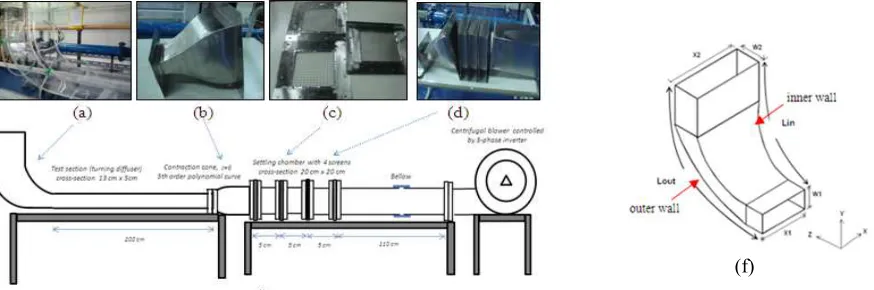
Fig. 1. (a) The test section was fabricated using acrylic, whereas the (b) settling chamber (c) contraction cone and (d) screens were fabricated using stainless steel (e) The experimental rig adopted several features of low
[image:2.595.87.524.489.634.2]subsonic wind tunnel system (f) The geometric layout of turning diffuser with 90o angle of turn
Table 1. The operating conditions
Rein
Vmax
(m/s)
Vinlet
(m/s)
2-D Turning Diffuser 3-D Turning Diffuser Pinlet
(E+05Pa)
Poutlet
(E+05Pa)
Pinlet
(E+05Pa)
Poutlet
(E+05Pa)
5.786E+04 14.36 12.92 1.013049 1.013235 1.012916 1.013120
6.382E+04 15.84 14.25 1.012978 1.013225 1.012844 1.013101
1.027E+05 25.48 22.94 1.012429 1.013090 1.012431 1.013053
1.397E+05 34.68 31.21 1.011471 1.012725 1.011645 1.012886
Results Analysis and Discussion
Effect of Varying Inflow Reynolds Numbers on Flow Uniformity.As depicted in Table 2, a 3-D
turning diffuser produces an outlet flow on average 29% more rapid than a 2-D turning diffuser. The best σu of 1.75 could be provided by a 2-D turning diffuser operated at Rein =5.786E+04.
However, the σu of a 2-D turning diffuser gets distorted more than a 3-D turning diffuser when it
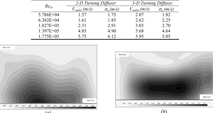
starts to be operated at Rein=1.027E+05. As shown in Fig. 2 and 3, the outlet flow distribution
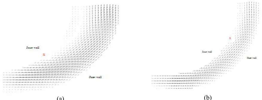
planes of both diffuser are almost alike, with the rapid flow mostly occurs within the outer wall region. Basically, the inner wall is subjected to the curvature induced effects, where under a strong adverse pressure gradient, the boundary layer on the inner wall is likely to separate, and the core flow tends to deflect to the outer wall. As marked in Fig. 4 and 5, the flow detachment occurs prior at 1/2Lin/W12-D for a 2-D turning diffuser, whereas approximately at 3/4Lin/W13-D for a 3-D turning
diffuser. The most distorted flow uniformity, σu=6.12 due to severe flow separation occurs when a
[image:3.595.74.527.298.538.2]2-D turning diffuser at maximum Rein=1.775E+05 is applied.
Table 2. Comparison of mean outlet air velocity, Voutlet (m/s) and flow uniformity, σu (m/s) of a 2-D and 3-D
turning diffuser
Rein
2-D Turning Diffuser 3-D Turning Diffuser Voutlet (m/s) σu (m/s) Voutlet (m/s) σu (m/s)
5.786E+04 1.57 1.75 2.07 1.82
6.382E+04 1.61 1.85 2.62 2.25
1.027E+05 2.31 2.91 3.03 2.70
1.397E+05 4.85 4.90 5.68 4.64
1.775E+05 5.75 6.12 5.95 5.05
(a)
[image:3.595.77.527.587.737.2](b)
Fig. 2. The outlet flow distribution plane of a (a) 2-D and (b) 3-D turning diffuser operated at minimum Rein= 5.786E+04
(a) (b)
(a)
[image:4.595.76.514.76.243.2](b)
Fig. 4. Flow structures at the center y-z plane of a (a) 2-D and (b) 3-D turning diffuser operated at minimum Rein= 5.786E+04
***X flow detachment point
(a)
[image:4.595.136.455.680.775.2](b)
Fig. 5. Flow structures at the center y-z plane of a (a) 2-D and (b) 3-D turning diffuser operated at maximum Rein=1.775E+05
***X flow detachment point
Effect of Varying Inflow Reynolds Numbers on Outlet Pressure Recovery. As shown in Table
3, the Cp of a 2-D turning diffuser improves with the increase of Rein. On the contrary, the Cp of a
3-D turning diffuser operated at high Rein=1.027E+04-1.775E+05 drops. This unusual trend could
not be described by the existing planes captured by PIV. Several other planes which are impossible captured by PIV will be acquired by CFD in the next progress. There would be basically a conflict in choosing the most optimum turning diffuser. In spite of the larger Cp that could be obtained by
applying a 2-D turning diffuser at Rein=1.027E+05-1.775E+05, the σu would be fairly disrupted. A
compromise between the maximum permissible pressure recovery and flow uniformity has to be sought and this basically depends upon the need.
Table 3. Comparison of outlet pressure recovery (Cp) of a 2-D and 3-D turning diffuser
Rein
2-D Turning Diffuser 3-D Turning Diffuser
Cp Cp
5.786E+04 0.191 0.210
6.382E+04 0.209 0.217
1.027E+05 0.216 0.203
1.397E+05 0.221 0.219
Conclusion and Future Directions
In conclusion, whenever the flow uniformity is of interest it is promising to apply a 3-D turning diffuser for Rein=1.027E+05-1.775E+05 and a 2-D turning diffuser for Rein=5.786E+04-6.382E+04.
On the other hand, it is viable of choosing a 3-D turning diffuser for Rein=5.786E+04-6.382E+04
and a 2-D turning diffuser for Rein=1.027E+05-1.775E+05 as the outlet pressure recovery becoming
the concern. The secondary flow separation occurs respectively at 1/2Lin/W1 and 3/4Lin/W1 for a
2-D and 3-D turning diffuser. The complexity of flow within a 3-D turning diffuser demands a critical justification which is yet considered novel. Several more configurations of a 3-D turning diffuser will be tested by means of CFD to establish the guideline.
References
[1] N.Nordin, S. Othman, V.R. Raghavan, M.F.M. Batcha, S.M. Idris, “Experimental investigation of pressure losses and flow characteristics in bend-diffusers by means of installing turning baffles”, presented at the 2nd International Conference of Mechanical Engineering, Putrajaya, Kuala Lumpur, June 6 –7, 2011.
[2]N. Nordin, V.R. Raghavan, S. Othman and Z.A.A. Karim,“Compatibility of 3-D turning diffusers by means of varying area ratios and outlet-inlet configurations", ARPN Journal of
Engineering and Applied Sciences, Vol. 7, No. 6, pp 708-713, 2012.
[3] R.W. Fox and S.J. Kline, “Flow regime data and design methods for curved subsonic diffusers,”
J. Basic Eng. ASME, vol. 84, pp. 303-312, 1962.
[4] T.P. Chong, P.F. Joseph and P.O.A.L. Davies, “A parametric study of passive flow control for a short, high area ratio 90 deg curved diffuser,” J. Fluids Eng., vol. 130, 2008.
[5] C.J. Sagi and J.P. Johnson, “The design and performance of two-dimensional, curved diffusers,”
J. Basic Eng. ASME, vol. 89, pp. 715-731, 1967.
[6] G. Guohui and B.R. Saffa, “Measurement and computational fluid dynamics prediction of diffuser pressure-loss coefficient,” Applied Energy, vol. 54(2), pp. 181-195, 1996.
[7] B. Majumdar and D.P. Agrawal, “Flow characteristics in a large area ratio curved diffuser,”
Proc. Instn. Mech. Engrs.,vol. 210, pp.65, 1996.
[8]E.G. Tulapurkara, A.B. Khoshnevis and J.L. Narasimhan, “Wake boundary layer interaction subject to convex and concave curvatures and adverse pressure gradient,”Exp. In Fluids, vol. 31, pp. 697-707, 2001.
[9] C.K. Nguyen, T.D. Ngo, P.A. Mendis and J.C.K. Cheung, “A flow analysis for a turning rapid diffuser using CFD,” J. Wind Eng., vol. 108, pp. 749-752, 2006.
[10] W.A. El-Askary and M. Nasr, “Performance of a bend diffuser system: Experimental and numerical studies,” Computer & Fluids, vol. 38, pp.160-170, 2009.
[11] Y.C. Wang, J.C. Hsu and Y.C., Lee, “Loss characteristics and flow rectification property of diffuser valves for micropump applications” Int. J. of Heat and Mass Transfer, vol. 52, pp. 328-336, 2009.
[12] N. Nordin, V. R. Raghavan, S. Othman and Z. A. A. Karim, “Numerical investigation of turning diffuser performance by varying geometric and operating parameters”, Applied Mechanics
and Materials Journal, Vol. 229-231, pp. 2086-2093, 2012.
[13] D.F. Young, B.R. Munson, T.H. Okiishi and W.W. Huebsch, A brief introduction to fluid mechanics, John Wiley & Sons, New Jersey, 2007.
[15] N.Nordin, Z.A.A. Karim, S.OthmanandV.R. Raghavan, “Verification of fully developed flow entering diffuser and particle image velocimetry procedures”, accepted to be presented at the 4th International Conference of Mechanical Engineering (ICME 2013), Batu Pahat, Johor, December 17 – 19, 2013.
[16] N. Nordin, Z.A.A. Karim, S. Othman and V.R. Raghavan, “Design & development of low subsonic wind tunnel for turning diffuser application”, Advanced Material Research Journal, Vol. 614-615, pp. 586-591, 2013.
[17]N. Nordin, S. Othman, V.R. Raghavan and Z.A.A. Karim, “Verification of 3-D stereoscopic PIV operation and procedures”, International Journal Engineering and Technology IJET/IJENS, , Vol. 12, Issue 4, pp. 19-26, 2012.