Model 340 Workstation's SPU
Service Manual
HP 9000 Series 300 Computers
Model 340
HP Part Number 98571-90030
FIIOW
HEWLETT
a:1!II
PACKARD
Hewlett-Packard Company
NOTICE
The information contained in this document is sublect to change without notice.
HEWLETT-PACKARD MAKES NO WARRANTY OF ANY KIND WITH REGARD TO THIS MANUAL, INCLUDING, BUT NOT LIMITED TO, THE IMPLIED WARRANTIES OF MERCHANTABILITY AND FITNESS FOR A PARTICULAR PURPOSE. Hewlett-Packard shall not be liable for errors contained herein or direct. indirect. special, incidental or consequential damages in connection with the furnishing, performance, or use of this material.
WARRANTY
A copy of the specific warranty terms applicable to your Hewlett-Packard product and replacement parts can be obtained from your local Sales and Service Office.
Copyright © Hewlett-Packard Company 1988
This document contains information which is protected by copyright. All rights are reserved. Reproduction, adaptation, or translation without prior written permission IS
prohibited, except as allowed under the copyright laws.
Restricted Rights Legend
Use, duplication or disclosure by the U.S Government Department of Defense is subject to restrictions as set forth in paragraph (bX3Xii) of the Rights in Technical Data and Software clause in FAR 52.227-7013.
Copyright © AT&T, Inc. 1980,1984
Copyright © The Regents of the University of California 1979, 1980, 1983
This software and documentation is based in part on the Fourth Berkeley Software Distribution under license from the Regents of the University of California
Printing History
New editions of this manual will incorporate all material updated since the previous edition. Update packages may be issued between editions and contain replacement and additional pages to be merged into the manual by the user. Each updated page will be indicated by a revision date at the bottom of the page. A vertical bar in the margin indicates the changes on each page. Note that pages whieh are rearranged due to changes on a previous page are not considered revised.
The manual printing date and part number indicate its current edition. The printing date changes when a new edition is printed. (Minor corrections and updates which are incorporated at reprint do not cause the date to change.) The manual part number changes when extensive technical changes are incorporated.
October 1988 ... Edition 1
November 1988 ... Edition 2. (Several part numbers changed and this edition includes the new part numbers.)
Notices
Radio Frequency Interference Statements
IFCC Statement
Federal Communications Commission Radio Frequency Interference Statement
(U.S.A. Only)
The Federal Communications Commission (in Subpart J of Part 15, Docket 20780) has specified that the following notice be brought to the attention of the users of this product.
Warning: This equipment generates, uses, and can radiate radio frequency energy and if not installed and used in accordance with the instructions manual, may cause interference to radio communications.
It has been tested and found to comply with the limits for a Class A computing device pursuant to Subpart J of Part 15 of FCC rules, which are designed to provide reasonable protection against such interference when operated in a commercial environment. Operation of this equipment in a residential area is likely to cause interference in which case the user at his own expense will be required to take whatever measures may be required to correct the interference.
'VCCI
Statement (Japan Only)
Manufacturer'S Declaration (Germany Only)
Herstellerbescheinigung
Hiermit wird bescheinigt, daB dieses Gerat in lJbereinstimmung mit den Bestimmungen der Postverfiigung 1046/84 funkentstort ist. Der Deutschen Bundespost wurde das Inverkehrbringen dieses Gerates angezeigt und die Berechtigung zur Uberpriifung der Serie auf Einhaltung der Bestimmungen eingeraumt.
Safety Considerations
WARNINGs, CAUTIONs, and Notes
Warnings, cautions and notes are used throughout this document to alert the user to conditions of importance. They are used as follows:
• WARNINGS contain information which, if not observed, could result in injury to personnel or loss of life.
• CAUTIONS contain information which, if not observed, could result in damage to or destruction of equipment.
• Notes contain information that will assist you in accomplishing the job.
Examples:
vi
NoticesWARNING
The power supply presents a hazard to personnel. Extreme care must be taken when connecting voltmeter probes to the test points. De-energize the product by turning it off and removing its power cord before connecting or removing test probes.
I
CAUTIONI
The printed circuit assenlblies in this product are susceptible to damage by electro-static discharge. Extrenle care must be taken when handling printed circuit assemblies. Use an Anti-static Workstation while handling printed circuit assemblies.
Note
Service Information Locator
On the next page is a Service Information Locator. First, find the information to reference in the left-hand column. Next, move to the right to a chapter number. Last, move up to the abbreviated lnanual title that has the information documented.
Chapter identifiers in the Locator use the following codes:
Chapter N urnber: Numbers, such as 2. Inclusive chapters, such as 4-6.
Letters, such as A for Appendix A. Appendices:
Entire Manual: All
Varies:
*
(Check Table of Contents or Index.)M:anuals identified in this locator are abbreviated by their initials:
Initials Manual Title Part Number
81M Model 340 Workstation's SPU Service Information Manual 98571-90030
SHB Model 340 Workstation's SPU Service Handbook 98.571-90039
TTM Series 200/300 Test Tools Manual 09800-90011
SPM HP 9000 Site Preparation Manual 09000-90041
PIN Product Installation Note
TDS Series 300 Technical Data Sheet/Price List
Video/Graphics Boards Information
These boards have service information located in other manuals identified in the following table.
Workstation
Model Part Number Title
340SRX 98720-·90030 HP 98720A Graphics Display Station Hardware Support Document
340CH 98550-·90000 HP 98550A Graphics Interface Familiarization Guide
98556-·90000 HP 98556A 2D Graphics Interface Familiarization Guide
340C+ 98549-90000 HP 98549A Graphics Interface Familiarization Guide
340MH 98548-·90000 HP 98548A Familiarization Guide
340M 98562-·90030 Model 330/350 Service Information Manual
Model 340 Workstation's SPU Service Information Locator
Service Information SIM SHB TTM SPM PIN TDS
Assembly replacement 2
Block diagrams 1-3 9
Booting Operating Systems 4
Computer tests 1, 5 2 1,2,3
Configurations 1,3 3 1,2 All
CS/80 tests 1, 5 5 4
Electrical requirements 1 1 3, A
*
Environmental requirements 1 2 4, A
*
Functional descriptions 3
HP-HIL device tests 2, 3
Installation 2 2 All All
I/O Bus architecture 1,3
Monitors 1 3 A
*
People who can help 1
Options / Accessories 1,3 3 All
*
Ord(\ring spare parts 6 8
Part numbers 6 8
Peripherals 1 3
*
Preventive maintenance 2
Product information 1 1 All All All
Product numbers 1 1,3 A All
Reference material 7 10 All
Repair Philosophy 1 1
Self-tests 4, 5 5 1,2
Service notes 1 11
Site preparation 2 All
System Functional Tests 1, 5 5 1,3
Systems 1 3
*
TrOll bleshooting 5 4 3
Turn-on 3, 4 4, 5
Table of Contents
Chapter 1:: Product Information
Introcluctiorl. . . .. 1
VVorkstation Configurations .. . . .. 1
DIO-I Accessory Cards Supported ... " :~
SPU Physical Identification ... 4
SPU l-Iard ware ... 5
P'ower SUf>ply ... 5
Processor Board . . . .. 5
Bus Architecture. . . .. 5
l\1elnory ... 6
Video/Graphics Boards ... 6
Illterfaces .. " ... 6
!(ey l)oard .. " . . . .. 6
Operating Systemls . . . .. 7
I-J[P-UX , ... " ... 7
E:ASIC 5.2 . .. . . . .. 7
Product Identification ... 7
Serial N urnbers . . . .. 7
Hardware Ternlinology ... 8
Software Tenninology ... 8
Hardware Support Docunlentation ... . . . .. 9
Service Manual . . . .. 10
Service Handbook ... 10
Test Tools Manual . . . .. 11
Service Notes. . . .. 11
Installation Notes. . . .. 11
Series 300 Configuration Reference Manual. . . .. 12
Site Preparation Manual. . . .. 13
Installation Reference ... 14
Technical Information ... 1.5 E:lectrieal ... . . . .. 15
Enviromnental. . . .. 15
Electronlagnetic Interference ... 1.5 Regulatory Requirements .. . . .. 15
F'hysical ... 16
Processor Board ... 16
~1:emory ... 17
I/C) Bus ... 17
\Tideo ... 17
Shipping Infornlation . . . .. 17
HP-HIL Accessories ... 18
Hewlett-Packard Support ... 19
Repair Philosophy ... 19
HP Repair Services. . . . .. 19
Repair by Customers ... " 19 Operating Systenls Support ... " 20 Chapter 2: Assembly Replacement Introduction ... " 21 Tools Required ... 21
Safety Precautions . . . .. 22
Electrical ... 22
Electro-Static Discharge ... 22
Mechanical ... " 23 Helpful Hints. . . .. 23
RenlOval Sequences ... " 23 Reference Diagram ... " 25 Proced ures ... " 28 Overview ... 28
DIO-1 Accessory Cards ... 28
Case ... 29
Case or Front Panel Replacenlent ... " 30 Fuse ... 31
Rear Panel ... " 31 Power Supply ... 32
Video/Graphics Boards ... 34
LGn Interface Board ... 36
R,AM Boards ... " 37 DIO-I Slot ... " 38 SPU Backplane ... " 39 ThinLAN Board ... " 40 AUI LAN Board ... " 41 Processor Board ... " 41 Chapter 3: Functional Description Hardware Overview ... . . .. 43
Processor Board ... " 43 Meillory ... 43
Video / Graphics ... " 44 System Interfaces ... " 44 Power Supply ... 45
Processor Board ... 47
Overview ... "... 47
Central Processing Unit ... ' ... " 47 Co-Processor ... " 49 Boot ROMs and Self-Test LEDs ... . . .. 49
I/O BllS ... " 49 Direct Memory Addressing. . . .. 49 Processor Board Interfaces ... " 50
RS-232 Interface ... 50
HP-IB Interface ... 51
HP-HIL Interface/Devices ... 52
LAN Interface Boards . . . .. 56
ThinLAN Board . . . .. 56
AUI LA='J Board ... 57
Memory ... '" ... " ... 58
Introduction. . . .. 58
RAM Architecture ... , 58
RAM Configuration . . . .. 59
Video/Graphics Boards ... 61
Small Computer Systems Interface . . . .. 62
SCSI Overview ... 62
Configuration ... 64
(jal)ling . . . .. 65
Third-Party Issues ... , ... 65
Functional Description ... ' ... 66
High-Speed HP-IB ... , ... 67
Chapter 4: Boot ROM Functions Introd.uction. . . .. 69
Power-Up/Self-Test Sequence ... 69
Configure Mode Software Override . . . .. 71
Extended Testing . . . .. 72
The Human Interface ... 72
Relnote Human Interface ... 73
Srnall COlnputer Systems Interface ... 76
Booting Operating Systems ... 78
Boot System Selection . . . .. 78
Boot System Priority Control. . . .. 80
Supported Boot Configurations ... 81
LAN Boot Operations . . . .. 81
Chapter 5: Troubleshooting Intro,dllction . . . .. 83
Analytic Troubleshooting ... . . . .. 83
lvIaterials Required. . . .. 83
Test LED Displays ... 83
Troubleshooting Procedures. . . .. 84
\Vorkstation Level. . . . .. 84
SPU Troubleshooting. . . .. 84
Inoperative Unit Procedure ... 85
Live Unit Procedure ... 86
Minimum Configuration ... 86
Functional Unit Troubleshooting ... 87
SCSI Test Connector. . . .. 87
:\1inimum Configuration ... 88
Self-Test . . . .. 89
Failure Indications ... 89
General Description of LED Failure Codes ... 90
Other Failure Indicat ions ... 94
LAN Boot Failures ... 95
Diagnostic Progranls . . . .. 97
HP-UX Diagnostics ... 97
Series 200/300 Test Tools ... 9S Series 300 System Support Tape . . . .. 99
Chapter 6: Parts Lists Parts Information ... 101
Introduction. . . .. 101
Cooperative Support Program ... 101
Exchange Parts ... 101
Parts List. . . .. 102
Chapter 7: References Irltroduction. . . .. 105
Service Information Locator. . . .. 105
Localized System Identification . . . .. 105
Related Hardware Documentation. . . .. 107
Hardware Support Documentation . . . .. 107 Installation Manuals/Notes. . . .. lOS Document Binders . . . .. lOS
Product Information
1
Introduction
Model 340 Workstation SysterIl Processing Unit's (SPU's) are market entry level versions of the Model :360 and 370 computers. Each provides good performance at low cost to meet the computer-·intensi ve requirements for design automation as well as scientific analysis and general purpose cornputation. These SPU's are also an enhanced versions of the Model 318 and 319 Workstation SPUs with improved video and graphics capabilities, added interfaces, and a faster clock speed.
The SPU is a lirIlited-configuration product. Depending on the workstation model, one of several video/graphics boards is used. It is upgradeable for memory and has LAN, High-Speed HP-IB or SCSI interface options. Certain user-installable DIO accessory cards can be used if the HP 98013A DIO Slot is installed. No expanders are available for the Model .340 Workstation's SPU.
Each SPU is cOlIlplete within the case. All Illemory, interfacing, video and processing functions occur within the case.
Workstation Configurations
Several configurations are available. You should refer to the current HP 9000 Series 300
Pricing Information and Technical Data Sheets to find out exactly what is currently offered. Different aIllounts of memory and interface options are available for installation by qualified service personnel.
Table 1-1 lists the standard Model 340 Workstation configurations.
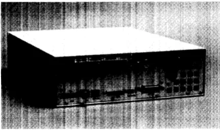
Table 1-1. Model 340 Workstation Descriptions
Workstation Product N arne /Description
Model 340SRX 98573C 3D Color Workstation; includes:
SPU with LGB Interface, DIO-1 Slot and 4 Mbytes RAM.
HP 98720A 3D Display Controller with 8 planes of frame buffer memory.
HP 98789A 16-inch High-Res Color Monitor.
Opt. 719: Substitute HP 98752A 19-inch High-Res Color Monitor for HP 98789A Monitor.
Model 340CH 98564G 2D Color Workstation; includes:
SPU with High-Res Color Graphics (1280 by 1(24) and 4 Mbytes RAM.
HP 98789A 16-inch High-Res Color Monitor.
Opt. 556: Add 2D Integer-Based Graphics Accelerator.
Opt. 719: Substitute HP 98752A 19-inch High-Res Color Monitor for HP 98789A Monitor.
Model 340C+ 98564C Color Workstation; includes:
SPU with High-Res Color Graphics (1024 by 768) and 4 Mbytes RAM.
HP 98785A 16-inch High-Res Color Monitor.
Opt. 719: Substitute HP 98751A 19-inch High-Res Color Monitor for HP 98785A Monitor.
Model 340MH 98563G Monochrome Workstation; includes:
SPU with High-Res Monochrome Graphics (1280 by 1024) and 4 Mbytes RAM.
HP 98788A 19-inch High-Res Monochrome Monitor.
Model 340M 98563E Monochrome Workstation; includes:
SPU with High-Res Monochrome Graphics (1024 by 768) and 4 Mbytes RAM.
HP 98786A 17-inch High-Res Monochrome Monitor.
[image:14.612.71.525.88.555.2]1010-1 Accessory Cards Supported
When the HP 9801:3A DIO Slot Upgrade is installed, only the DIO-I accessory cards listed below are supported:
• HP 3t>59JA HP-·UX Gateway /SNA Interface. • HP 50955A 3278 Emulator.
• HP 50962A SR~1 Interface. • HP 98255A EPROM Board. • HP 98259A Bubble Memory Card. • HP 98286A DOS Coprocessor. • HP 98622A 16-Bit GPIO. • HP 9862:3A BCD Interface. • HP 98624A HP-·IB Interface.
• HP 98625B High-Speed HP-IB Interface. • HP 98626A 50-Pin RS-232C Interface. • HP 98628A Datacomm Interface. • HP 98630A Breadboard Interface Card.
• HP 9863:3A G944A Multi-Programmer Interface. • HP 98640A 7 -Channel A/D Interface.
• HP 98641A RJE 2780/3780 Interface. • HP 98642A 4-Port RS-232 MUX Interface. • HP 9864:3A LAN Interface.
• HP 98644A RS-232C Interface. • HP 9864GA VM:Ebus Interface. • HP 98647A PC·-IB Interface. • HP 98658A SCSI Interface.
• HP 98691A Programmable Datacomm Interface. • HP 98725A Local Graphics Bus Interface.
SPU Physical Identification
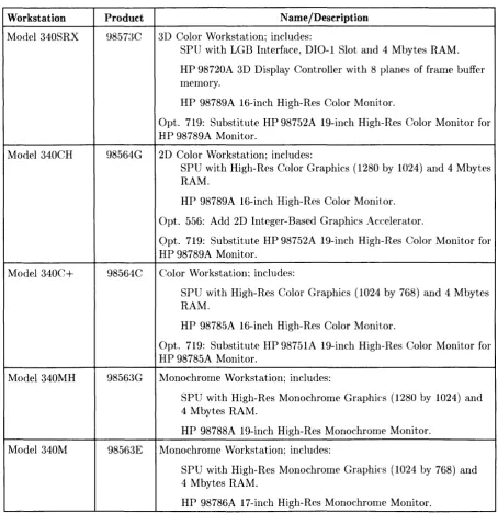
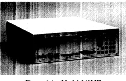
Depending on the interface options and video boards used, each version can usually be identified by the rear panel configuration. Figure 1-1 shows each Model ~340 Workstation rear panel.
Figure l-la. Model 340SRX
Figure I-lb. Model 340CH and 340C+
Figure I-Ie. Model 340MH
[image:16.612.193.410.436.574.2]Figure I-Id. Model 340M
SPU Hardware
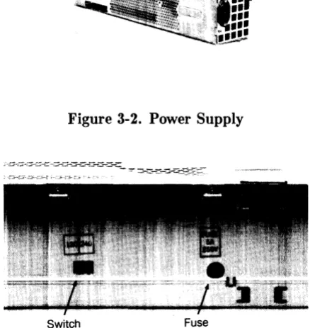
Power Supply
A modular power supply is provided for the voltages required. Its voltage select switch IS
user-accessible.
Processor Board
Here's a llist of what the processor board has:
• MC680:30 CPt:" at 16.67 MHz.
• MC68882 Floating-Point Coprocessor.
• Parity-Checking RAM Controller.
• HP-IB (IEEE-488) Interface with two-channel DMA controller.
• RS-2:~2C Serial Interface with DB25 connector.
• HP-HIL [nterface.
Bus Architecture
A 32-bit systern bus connects the video/graphics, SCSI if installed and RAM to the processor board. If an HP 98013A DIO-I Slot is installed, ribbon cables connect its DIO backplane to the SPU backplane. LAN interface is provided through the LAN connector to the processor board.
[image:17.612.202.418.50.179.2]Memory
Up to four HP 98268A 4 MByte RAM boards may be plugged into the processor board. Depending on the specific workstation model, different amounts of RAM is installed.
Video/Graphics Boards
High-resolution color or monochrome video/graphics is output to the workstation's monitor through one of several video/graphics boards. A list of video/graphics boards supported is shown below with the workstation model each is supplied with:
• Model 340SRX: 3D Color Graphics Interface.
• Model 340CH: Color (1280 by 1024).
Option 556 adds the 2D Integer-Based Color Graphics Accelerator.
• Model 340C+: Color (1024 by 768).
• Model 340MH: MonochrOlne (1280 by 1024).
• Model :~40M: Monochrome (1024 by 768).
Interfaces
Optional interfaces are available that provide additional capability in addition to those on the processor board:
• Option 006 - One DIO-I slot. Also available separately as an HP 9801:~A DIO-I Slot Upgrade. It's standard with the Model 340SRX and supplied with Options 010 and OIl.
• Option 010 - High-Speed HP-IB Interface. Standard with the lVlodel 340SRX.
• Option 011 - Snlall Computer Systems Interface (SCSI).
• Opt. 015 - AUI LAN (requires external media attachment unit).
• Opt. 017 - ThinLAN with built-in ThinMAU and BNC "T" connector.
Note that Options 010 and OIL cannot be installed together because each occupies the same slot in the SPU.
Keyboard
Standard keyboard is the Integrated Terminal Format (ITF) HP 46021A Keyboard. It connects to the HP-HIL connector through the rear panel.
Operating Systems
HP-UX
Series 300 HP-UX, Revision 6.2 or later, is supported in Model 340 Workstations.
BASIC 5.2
Supported as a serviee tool only, the HP 9861~~D Series 300 BASIC 5.2 operating system may be used to test the workstation. BASIC does not have drivers for the LGB interface used in Model 340SRX workstations.
Product Identification
Several terms in this manual are used to describe and identify the various parts of the SPU. This section explains the terms used to improve your understanding of service information.
Serial Numbers
The Model 340 Workstation SPU's serial number is on the rear panel. Other equipment in the workstation will also have its own serial number. An example serial number is explained below:
Serial No. XXXX A 01234 Location: On the rear panel.
~~'-v-'"
I
I
Description:5-digit unique workstation identifying number.
Country of Origin Code.
' - - - S P U Code, deeoded as:
First 2 digits
+
60=
Last 2 digits of yearSPU was introduced or significantly ehanged. Last 2 digits
=
number of week in year SPUwas introduced or significantly changed.
Hardware Terminology
Hardware means the physical elements of this workstation. Different parts and locations of hardware items arc explained below.
Product Terms/Conventions
The following terms are used to describe products and their main parts and areas:
• SPU - System Processing Unit, a box containing the power supply, processor board and other assemblies sHch as RAM add-on or interface boards.
• Internal (circuit) - A circuit, such as an interface, that is part of the processor board. Internal does not mean "inside the SPU's case" .
• External (circuit) - A circuit that is located on an assembly other than the processor board. External does not mean 'outside the SPU's case'.
• Peripheral- A device external to the SPU, such as a keyboard, monitor, disc drive, plotter, printer, etc.
• System - An SPU with OIle or more peripherals connected together to run an application for a desired end result.
Printed Circuit Assemblies
Printed circuit boards in the SPU and are made of several component parts. In this manual, boards identify the printed circuit assemblies installed inside the SPU. Boards are not usually removed or installed by llsers.
Printed circuit cards are those llsed in the DIO-I slot. They are usually installed by users.
Software Terminology
As used in this manual, software refers to infonnation stored in, or on a device. Typically, this information can be changed and can be transferred to another location in the workstation. Types of software are:
• Firmware - The data or instructions in Read-Only-Memory (RONI) chips.
• Operating Systems - Computer languages, such as BASIC, Pascal, and HP-UX. They have various commands, statements, and keywords that when executed by the CPU in a particular sequence, cause SPU to manipulate data to SOlIle desired end result.
• Application Program - A series of operating system prograrn lines in a specific sequence to cause specific actions, such as accounting, electro-mechanical design, data sampling and output, etc. This information is sometilnes referred to as software as it is information that is stored in or on a lnedium and can be transferred.
Hardware Support Documentation
The purpose of this SPU's Hardware Documentation is to support the installation and mainte-nance of these products. Hardware Support Documentation consists of these manuals for the HP 9000 Series :300 Model 340 Workstation's SPU:
• Service ManuaL
• Service Handbook.
• Service Notes.
• Series 200/:300 Test Tools Manual.
• HP 9000 Series 200/300/500 Site Preparation Manual.
• Series 300 Con1puter System Configuration Reference.
The following Inanuals also relate to hardware:
• Various Installation Notes.
• Series 300 Installation Reference.
• Series 200/:300 Peripheral Installation Guide.
A complete listing of titles and part numbers is in Chapter 7 of this manual and the SPU's Service Handbook, Chapter 10.
Service Manual
This manual (the one you're reading now) contains tutorial information on the SPU's features, functional descriptions of each assembly, and how to replace these assemblies.
Its purpose is to serve as a learning tool in training environments wherein the service person learns how the SPU works and its parts are replaced. Most of the information in the Service Information Manual is not found in the Service Handbook.
Organization of the Service Manual is found in the Table of Contents.
Service Handbook
This manual is intended to be used on site during service situations. It contains information useful to configuring, troubleshooting, and replacing parts. It is organized as follows:
Chapter No. and Title
Chapter 1: Product Information
Chapter 2: Environmental, Installation, and PM
Chapter 3: Configuration
Chapter 4: Troubleshooting
Chapter 5: Tests
Chapter 6: Adj ust ments
Chapter 7: Systems
Chapter 8: Replacement Parts
Chapter 9: Diagrams
Chapter 10: Reference
Chapter 11: Service Notes
10
Product InformationContents
Has a brief description of the product, along with configu-ration and similar information. Product technical data is also listed.
Gives power requirements, and power cord data, and instal-lation information. If preventive maintenance is required, it is shown in this chapter.
Lists product configurations and explains what each one is.
Lists tools required, including Test Tools, and explains several troubleshooting procedures. Flow charts are fre-quently used.
Lists tests to run to check out the SPU, some peripherals, and interfaces.
There's no adjustments for the SPU.
Refers to the Series 300 Pricing Information and Technical Data sheet for current bundled system configuration.
Lists part nUlnbers for all field-replaceable parts and ex-plains how they may be obtained.
Block diagrams of the products are shown here.
Other documentation related to these products are listed here with their part numbers.
'Test Tools Manual
Series 200/300 Test Tools Manual supports a software package for diagnosing Model 340 Workstations. The Test Tools manual and its associated discs or tape permit troubleshooting workstations in failure analysis. Part numbers for the complete Test Tools packages are:
• 09800-12300 for 3.5-inch disk drives. • 09800-12700 for 5.25-inch disk drives. • 985~51-10835 for 0.25-inch tape drives.
Contents of the four parts of the Test Tools Manual are: Part No. and Title
Part I: Introduetion and Built-In Tests
Part II: Computer Tests
Part III: System Functional Tests
Part IV: CS / 80 Exercisers
Service Notes
Contents
Introduces the Test Tools package and overviews the SPU self-tests and explains what the different tests do. Covers loading and running of Series 300 Computer Tests. Each test is explained as to what it does. Error messages are listed and explained.
Tells how various SPU-peripheral tests are loaded and run. Tests are explained, error messages shown and defined. Examples of some tests are given. Includes tests for HP-HIL devices.
Explains how tests for CS/80 disc drives are loaded, ran, and results are interpreted. Error messages are shown as well as several examples of running the tests.
When a situation occurs that effects serVICIng of the SPU that is not covered in existing documentation, a Service Note is written to explain it. Service Notes are distributed through a Subscription Service to HP Customer Engineers and to customers on the Cooperative Support Program for these products. Being half-page in size, they are intended to be placed in Chapter 11 of the Model 340 Workstation SPU's Service Handbook.
Installation Notes
Each separately available accessory or upgrade has an Installation Note packaged with it. These Notes have instructions for configuring and installing the hardware. In addition, an Installation Picture Guide is provided with each bundled system showing how to install and turn on the workstation.
Series 300 Configuration Reference Manual
All supported configurations of Series 300 Computer Systems are explained in this manual.
Section No. and Title
Section 1: Configuration Overview
Section 2: Operating Systems and Application Software
Section 3: System Packaging
Section 4: Interface and Peripheral Selection
Section 5: Support Services
Appendix A: Detailed Product Reference
12
Product InformationContents
Has configuration worksheets to assist in planning the application.
Covers supported languages and media options.
Lists the configurations, features and options available.
Explains Interfacing, networking, mass storage, moni-tors, printers, and other output peripherals.
Overviews Customer Training, installation and support services, and consulting.
Site Preparation Manual
Explains site preparation and how to prepare the site for hardware installation. Covers physical, environmental and electrical requirements. Its organization is shown below.
Chapter No. and Title
Chapter 1: Introduction
Chapter 2: Responsibilities
Chapter 3: Preparing the Electrical Environnlent
Chapter 4: Preparing the Physical Environment
Chapter 5: Providing Other Necessities
Chapter 6: Equipment Arrangenlent and Space Planning
Chapter 7: When Your Computer Arrives
Appendix A
Appendix B
Contents
Explains the purpose and contents of the Site Prepara-tion Manual.
Identifies customer and HP responsibilities for preparing the HP 9000 System site. Includes a time frame for setting up the workstation, and identifies people who can provide assistance.
Includes power technical data, dealing with electrical in-terference, connecting cables, and data communication configurations.
Explains heat and humidity considerations, airborne contaminants, and shipping weights and dimensions for movement and storage.
Covers media storage, equipment and record protection, supplies, and nearby telephones for assistance which are an integral part of preparing for and sustaining the operation of a workstation.
Provides information and guidelines for planning the location of the workstation equipment at your site.
Discusses the final preparation for system arrival, coor-dinated deliveries, arrival dates, how to check for dam-age in shipment, unpacking the cartons, and scheduling the installation of HP 9000 Systems.
Lists product technical data for electrical requirements, heat generation, temperature and humidity require-ments, and shipping dimensions.
Contains forms to use for preparing the site, such as Pre-Installation Worksheet, Shipment Scheduling Form, and a Site Completion Checklist.
Installation Reference
The workstation has step-by-step procedures for installing each part. An Installation Card is a pictorial set of instructions to show installers how to unpack, connect, and power up the SPU, disc drive, and monitor. More detailed information is contained in the Installation Reference. To install the operating system and/or application program, the docuInents supplied with these software products should be referred to.
Organization of the Installation Reference is:
Chapter No. and Title
Chapter 1: Introduction
Chapter 2: Installing Your Computer
Chapter 3: Installing Accessories
Chapter 4: Installing Your Key board and Monitor
Chapter 5: Installing HP-IB Peripherals
Chapter 6: Installing Non-HP-lB Peri pherals
Chapter 7: Reading the Self-Test
Reference
Glossary
14
Product InfonnationContents
Covers how the guide is organized and explains some SPU fundamentals.
Includes procedures on positioning the SPU, checking volt-age settings, connecting power cords, and turning on the SPU.
This chapter covers accessory configuration and installation.
This chapter covers keyboard and rnonitor installation.
Standard HP-IB peripheral configuration and connection procedures.
Peripheral configuration and connection procedures other than HP-IB.
Covers procedures performed by self-test and how to in-terpret the results of the self-tests. Error messages are explained and help is provided should the user get into trou ble at this point.
This chapter has information regarding internal configu-ration switches, running extended tests, Boot ROM error messages and tutorial information on data communications and interfacing.
Technical Information
Note
Technical information listed below should not be interpreted as spec-ifications. Official specifications are listed in the HP 9000 Series 300
Hardware Technical Data and Pricing Sheet.
Electrical
Line voltage/frequency
Line transient spike immunity (1 nsec rise, 800 nsec duration) Power Consurnption
Current Requirements
Maximunl Heat Dissipation
I:nvironmental
Operating telnperature Operating humidity Operating altitude
115 V ac @ 48-66 Hz
230 V ac @ 48-66 Hz
1 KV dc
155 Watts maximum 2.6 A @ 115 V ac 1.5 A @ 2:30 V ac 570 BTU/hr 167 Kcal/hr
o -
550C (32 - 1040 F) 5 - 80% relative
4572 metres (15000 feet)
Electromagnetic Interference
Standards rnet FCC Class A VCCI Class 1
VDE Class B, VDE 1046/84
Regulatory Requirements
Standards rnet UL 478, 5th Edition CSA 220-M1986
IEC 380, 2nd Edition; 435, 2nd Edition
Physical
Dinlensiolls Height Width Length WeightProcessor Board
CPU TypeClock Frequency
Internal Architecture
Address range
Data bus
Floating point Coprocessor
Type
Clock Frequency
MMU
Type
Clock Frequency
LAN Interface
Media
Protocols
Data Rate
Parallel Interface
Type
Data Rate
104 mm (4.1 inches)
325 mm (12.8 inches)
444 nlm (17.5 inches)
4.5E> kg (10 pounds) maximum
Motorola M C68030
16.67 Mhz
32-bit data and address registers
4 Gbytes virtual mapped to 4 G bytes physical
32-bit synchronous
Motorola MC68882
16.67 Mhz
Motorola MC68852
16.67 Mhz
LAN coax cable (RG 58U)
IEEE 802.:3, Ethernet
10 Mbits /sec
HP-IB (IEEE 488)
350 Kbyte/sec
N uInber of connected devices
Serial Interface
15 per interface devices supported
Type
Capacitor-backed Real-Tilne Clock
Resolution
Accuracy
Clock life
16
Product InformationRS-232C standard
10 milliseconds
±5 seconds/day
DMA
Input Clock
Channels
10 MHz
2
Channel Priority
Channel Arbitration
Bus Arbitration
Transfer Types
ProgramlTIable, high or low, each channel
Round-robin
010 daisy chain
8-bit (byte) 16-bit (word) 32-bit (long word)
Max Transfers 4G transfers per arming
Bus Bandwidth Use Limits
Min Cycle Time
Programmable: 100%, 50%, 25%, 12.5%
300 ns
Max Theoretical Transfer Rate
Typical Burst Transfer Rate
Interru pt levels
13.3 Mbytes/sec
2.8 Mbytes/sec
Programmable: 7, 6, 5, 4, 3
FFFFFFFF - 00000000 Address range
Memory
A1TIolmt
Type
A verage cycle time
11/0 Bus
Width
Bus bandwidth
Video Interface
Shipping Information
4, 8, or 16 Mbytes
Byte parity error-checking
300 nsec
32 bits address; 16 bits data
6 Mb/sec
High-Resolution Color
The shipping container for each SPU includes the Localization Kit, which includes power cords, keyboard cable, HP-HIL cable, Safety and Regulatory Information, and Installation Picture Card.
Shipping Weight
Container Dirnensions
9.1 kg (20 pounds)
Width - 533 rnm (21 inches) Length - 584 mIn (23 inches) Depth - 292 mm (11.5 inches Cube - 0.085 m3 (3.21 feet3)
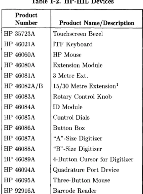
HP-HIL Accessories
Listed below are HP-HIL accessories compatible with the Model 340 Workstations. For a complete list, consult the HP 9000 Series 300 Hardware Technical Data and Price List.
Table 1-2. HP-HIL Devices
Product
Number Product Name/Description
HP 35723A Touchscreen Bezel
HP 46021A ITF Keyboard
HP 46060A HP Mouse
HP 46080A Extension Module
HP 46081A 3 Metre Ext.
HP 46082A/B 15/30 Metre Extension!
HP 46083A Rotary Control Knob
HP 46084A ID Module
HP 46085A Control Dials
HP 46086A Button Box
HP 46087A "A" -Size Digitizer
HP 46088A "B" -Size Digitizer
HP 46089A 4-Button Cursor for Digitizer
HP 46094A Quadrature Port Device
HP 46095A Three- Button Mouse
HP 92916A Barcode Reader
[image:30.615.188.417.109.418.2]Hewlett-Packard Support
Support services and policies mentioned in this section are subject to change. Please consult your local Hewlett-Packard Sales and Service Office for the current support policies.
Repair Philosophy
Field Repair Philosophy for this SPU is assembly, or board level. This means that when a failure occurs, the probleln is diagnosed to the assembly having the failed part. That assembly is then replaced. Replacernent assemblies are available through local HP Sales and Service Offices.
SOllle assenlblies nmy be exchanged for rebuilt ones. Other assemblies are only available as new ones. Refer to Chapter 6, or the Service Handbook, Chapter 8, for information on replacement parts.
Schematics
In support of the repair philosophy, this lllanual contains information to the assembly level. Schematics are not available for these products.
Supported Configurations
Only workstations with Hewlett-Packard approved parts, accessories, peripherals, operating systems and application programs are supported by Hewlett-Packard. Any workstation with other than HP approved hardware or software connected or installed must have the non- HP approved hardware and software removed by the customer before On-Site repair is accomplished.
HP Repair Services
There are many hardware support options available, from utilizing customer's maintenance groups to buying full support from the local HP Sales Office. Please contact your local Hewlett-Packard Sales and Service Office for complete information.
Hewlett-Packard provides on-site repair services for Model 340 Workstation SPU's.
~10re information is available in the HP 9000 Series 300 Pricing Information Sheet Contact your local HP Sales and Service for complete information on these services. Each is briefly described below.
Repair by Customers
In addition, customers may obtain service training courses and spare parts to do their own repair. Contact your nearest HP Sales and Service Office for information concerning service training, special tools and test equipment, and spare parts.
Operating Systems Support
HP-UX Installation Services
A set of lnodular services that provide expert installation of hardware, operating system, and selected HP DesignCenter applications is available. They allow users to lnake productive use of their system in the shortest possible time. Services include:
• Interconnection of systelll hardware.
• Formatting discs.
• Loading and configuration of the HP-UX Operating System.
• Loading applications.
• Verification of systeln operation.
• Review of the system for its System Adlninistrator.
Refer to the HP 9000 Series 300 HP- UX Installation Services Technical Data (5954-9695) for details and complete information.
Primary Support
There are numerous operating system support options:
• Account lV1anagement Support (AMS) provides a local SE, on-site assistance, one Re-sponse Center caller and one alternate for telephone assistance, and a Software Materials Subscription.
• Response Center Support (RCS) provides one Response Center caller and one alternate for telephone assistance, and Software Materials Subscription.
• Software Materials Subscription (SMS) provides software and manual updates, Software Status Bulletins, and HP communicator magazine. Updates to ROM-based systems are not provided.
Support For An Additional System
The following options support an additional system:
• Additional System Coverage extends AMS or RCS coverage on the operating system to one additional system under the same system manager. All support is delivered through the central systeln.
• Extended Materials Support extends SMS by providing the right to make one copy of all central system lllaterials for use on one additional system.
• Additional Response Center Caller provides one additional caller and one alternate for access to the HP Response Center
• Manual Update Service (MUS) provides one copy of updates to software reference manuals.
• Software Notification Service (SNS) provides issues of the HP COlllmunicator and Software Status Bulletin.
Assembly Replacement
Introduction
Tools Required
I
CAUTIONI
In this SPU, special screws requiring Torx® T-10 or #1 Pozidriv screwdrivers are used. Do not use other screwdrivers as they will danmge the screw head recess.
All field replaceable parts can be accessed with these tools:
• T-10 Torx® screwdriver, 4-inch (100 mm) blade.
• Pozidriv® #1 screwdriver, 4-inch (100 mm) blade.
• One each of these nut drivers .
• :3/1(>-inch (8720-0001).
• 5.5mm (8720-1220) .
• 9/32-inch.
• 5/8-inch open-end wrench.
• 9/16-inch open-end wrench.
I
CAUTIONI
A static-free Workstation (9300-0794) should be used as a work surface. Anti-static bags should be used to store assemblies in.
2
A unique feature of this SPU is that once the internal assembly is out of the case, no fasteners are used to hold the printed circuit assemblies in place. Only the rear panel has screws and locknuts to hold assemlblies, interface connectors and the case in place.
Safety Precautions
As with any electrical/electronic product, certain safety precautions must be practiced. These safety precautions, when followed protect both you and the equipment from injury and possible permanent damage.
Electrical
WARNING
Always turn off the SPU and remove the power cord before removing the case to remove or replace an assembly. If maintenance requires power to be applied while the case is removed, proceed only with extreme caution using safe, live-unit maintenance procedures. Do not touch energized components in the SPU.
Heed and follow all "WARNING-HAZARDOUS VOLTAGE" labels. Failure to follow these safety precautions may result in serious injury, or worse.
Electro-Static Discharge
Integrated circuit components can be damaged by electro-static discharge. It doesn't make any difference whether the IC's are installed on a printed circuit board or laying on a table. Static charges can build up in people to a potential of several thousand volts by simply walking across a room.
These circuits in the SPU and peripherals can be protected by using a static free workstation and wearing clothes that do not hold static charges before handling any of the SPU's PC boards.
When you need to remove or install a part, turn off power to the SPU first. With the static free workstation in place, touch sheet 111etal with your fingers before touching the printed circuit assembly. If the assembly is not going to be re-installed, place the assembly in an anti-static bag.
Following these precautions will extend the life of the computer products you maintain.
Mechanical
I
CAUTIONI
Adequate support of the processor or SPU backplane boards is required at their connectors when removing or installing boards to prevent flexing and possible failure of the traces inside these boards.
Apply pressure on the component side of the processor/backplane boards when removing other boards from them. Apply pressure on the back side of the processor/backplane boards when installing other boards in them.
If insertion resistance seems high, check the male connectors for bent pins.
Helpful Hints
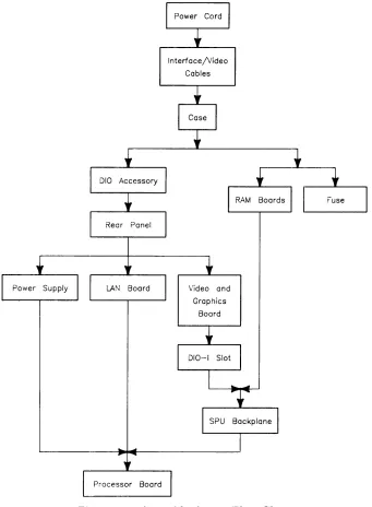
Removal Sequences
Figure 2-1 is an Assembly Access Flow Chart showing the sequence for removing parts. To use this chart, identify the part to be replaced at the bottom of the chart. Then start at the top of the chart and work through the steps toward the part to replace. Use this chart as a guide to install assernblies by starting at the bottom and working toward the top.
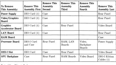
Table 2-1 also lists each assembly and what needs to be removed before that assembly can be removed.
Referencing the SPU's Service Handbook, Chapter 8, Replaceable Parts, as you remove each assenlbly /part for the first time will help associate the part numbers with their respective assemblies.
Interface/Video
Cables
Video and
Graphics
Board
Figure 2-1. Assembly Access Flow Chart
[image:36.611.138.479.45.509.2]Table 2-1. Disassembly Sequence
Remove This Remove This Remove This
To Remove Remove This Assembly Assembly Assembly Remove This
This Assembly: Assembly First Second Third Fourth Assembly Last
Power Supply DIO Card (1) Case Rear Panel
Video / Graphics DIO Card (1) Case Rear Panel
Board
Graphics DIO Card (1) Case Rear Panel Video Board
Accelerator Board
LAN Board DIO Card (1) Case Rear Panel
RAM Board Case
Processor Board DIO-I Card Rear Panel RAM, LAN Video, Power Supply
and Case Boards Backplane
Boards
DIO-I Slot DIO Card Case Rear Panel Video Board
SPU Backplane Case Rear Panel RAM Boards Video Board DIO-I Ribbon
Cables (1)
Note (1): If installed.
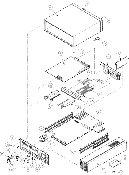
Reference Diagram
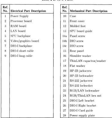
Table 2-2 lists a reference number with each SPU field replaceable part. Reference numbers are the same as those in the exploded view in Figure 2-2. These should help you determine parts orientation and identification for their removal and installation.
[image:37.612.73.533.70.327.2]Table 2-2. SPU Parts
Ref. Ref.
No. Electrical Part Description No. Mechanical Part Description
1 Power Supply 10 Case
2 Processor board 11 Front cover
3 RAM board 12 Molded foot
4 LAN board 13 SPU board guide
5 SPU backplaIH' 14a Panel screw
6 Video/graphics board 14b DIO screw
7 D I 0-I backplan(\ 14c DIO screw
8 DIO-I short cable 15 Rear panel
9 DIO-I long cablf' 16 Shoulder washer
17 ThinLAN capacitor/washer
18 Flat washer
19 HP-IB jackscrew
20 HP-IB lockwasher
21 RS-232 jackscrew
22 RS-232 lockwsher
23 RGB/LAN lockwasher
24 RGB/ThinLAN hex nut
25 DIO-I Left bracket
26 DIO-I Right bracket
27 DIO-I Card guide
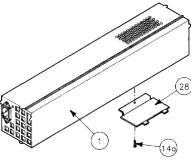
28 Power supply plate
[image:38.615.117.493.54.450.2]6
I
A
B
d,
~
. / / :/ / I 5
I
I
Figure 2-2. SPU Exploded Diagram
I
I
/ '
[image:39.612.90.506.46.611.2]Procedures
Overview
In this section, procedures are listed for renloving and installing each assembly. For each assembly, a list of Preliminary Requirements is provided indicating what should be done in what order before removing the assenlbly.
Instructions are based on the hardware orientation shown in Figure 2-3.
Figure 2-3. Hardware Orientation
010-1 Accessory Cards
Preliminary Requirements
Turn OFF the SPU and remove these items:
1. Power cord.
2. Any interface cables connected to the DIO-I card.
Removal
1. Loosen the thumbscrews on each side of the DIO-I card's backpanel.
2. Slide the 010-1 card out of its slot.
Installation.
To install a DIO-I card, reverse steps 1 and 2 in the removal procedures, then reconnect the interface cables.
Note
RFI clips (5001-9039) must be installed on the DIO-I card backplate to ensure RFI is kept to minimum levels.
C:ase
The case needs to be removed to replace these printed circuit assemblies:
• RA~1 boards.
• Power supply.
• Fuse.
• Video/graphics boards
• DIO·-I backplane and ribbon cables.
• SPU backplane.
• Processor board.
• LAN board.
Preliminary Requirements
Turn OFF the SPU and remove these items in the order listed:
1. Power cord.
2. Video and interface cables.
F;lemoval
1. Remove the seven screws (Figure 2-4) holding the rear panel to the case.
Figure 2-4. Rear Panel Case Screws
2. Set the SPU on its bottom.
I
CAUTIONI
After the case is removed, the ON/OFF switch shaft extending from the power supply can be easily broken. Do not set the internal assernbly in a rnanner to put pressure on the switch shaft.
3. Slide the SPU's internal assembly out of the case.
Installation
To install the case:
1. Set the case on its bottom.
2. Ensure the RAM boards are fully seated in their connectors.
3. Start the internal assembly into the case.
4. Align the rails under the processor board with the rail guides in the bottom of the case.
5. Slide the internal assembly all the way into the case.
6. Install and fasten the seven rear panel screws.
Case or Front Panel Replacement
If the case or front panel is damaged, both parts must be replaced. The front panel cannot be removed from the case without damaging the metal fingers in the case. To replace either the case or front panel, these new parts are needed:
• Case.
• Front panel.
• Name label.
• Regulatory Label
Preliminary Requirements
Turn OFF the SPU and remove these items in the order listed:
1. Power cord.
2. Case.
Installing the Front Panel
1. Align the new front panel's attaching pins with their holes in the front of the case.
2. Press the front panel firmly and completely on to the case.
3. Remove the molded feet from the old case by unsnapping them from the bottom.
4. Install the molded feet into the new case.
5. Remove the new name label from its backing and press it into place in the upper left-hand recess on t he front panel.
6. Remove the new regulatory label from its backing and press it into place on the bottom of the case over the voltage select switch hole like the old case.
7. Install the internal assembly in the case.
Fuse
Preliminary Requirements
Turn OFF the SPU and remove these items:
• Power cord.
• Internal assembly
Removal
1. Insert a fiat-tipped screwdriver in the fuse holder and rotate it counter-clockwise and remove the fuse holder.
2. Remove the fuse from the fuse holder.
Installation.
To install a fuse1 reverse steps 1 and 2 in the removal procedures.
Rear Panel
~(ith the case slid off the internal assembly about two inches
(5
cm), only the rear panel needs to be removed to replace the LAN boards.For all other printed circuit assemblies, the internal assembly must be removed from the case.
Preliminary Requirements
Turn OFF the SPU and remove these items in the order listed:
1. Power cord.
2. Video and interface cables.
3. Any DIO-I card installed.
Removal
Refer to Figure 2-5 for rear panel fastener locations.
Figure 2-5. Rear Panel Fasteners
1. Remove the seven screws holding the rear panel to the case.
2. Remove the rear panel's interface port fasteners in the back panel as follows: a. Video connector lock nuts, using the 9/16-inch open-end wrench. b. HP-IB, using the 9/32-inch nutdriver.
c. RS-232, using the 3/16-inch nut driver. d. ThinLAN:
• BNC connector nut, using the 9/16-inch open-end wrench. • Rear panel cover plate screw, using the Torx screwdriver.
Note that the capacitor-washer next to the rear panel rnay be cracked. If so, it will need to be replaced during rear panel installation.
e. AUI LAN: slide the connector clip to the right side (left, looking from the rear) to the unlocked position.
f. LGB interface (if installed), use a #1 Pozidriv screwdriver.
3. If a DIO-I slot is installed, use a Torx T-10 screwdriver to remove the four screws holding the DIO-I card guide to the rear panel.
4. Remove the power supply grounding screw (Figure 2-5).
5. Pull the rear panel, power supply side first, away from the internal assembly.
Installation
To install the rear panel:
1. Place the rear panel in position on the internal assembly aligning the four power supply tabs and four SPU card cage alignment pins (two on each side) with their respective holes in the rear panel.
2. Reverse the first four removal steps.
Power Supply
Note
The power supply assembly does not have any internal replaceable assemblies except for the fuse. All parts, including the fan, line filter, fuse holder, printed circuit board and metal case are available only as a complete unit.
Preliminary Requirements
Turn OFF the SPU and remove these items in the order listed:
1. Power cord.
2. Video and interface cables.
3. Case ..
4. Rear Panel.
Removal
1. Remove the power supply cover plate screw (Figure 2-6).
This screw goes through the processor board extension and must be rernoved before the power supply can be removed from the processor board.
Figure 2-6. Power Supply Cover Plate
2. Raise the right edge of the cover plate and remove the cover plate from the power supply.
3. Lay the internal assembly on a fiat surface.
4. Remove the power supply by sliding it to the left disconnecting the processor board's connector from the power supply.
I
CAUTIONI
Note the position of the voltage range select switch. The replacement power supply must have its voltage range switch in the same position.
[image:45.614.208.397.242.400.2]Installation
To install a power supply, follow these procedures:
1. Verify the voltage select switch is in the correct position.
2. Set the power supply on its left side and position the processor board (or the rest of the internal assembly) as shown in Figure 2-7.
Figure 2-7. Positioning Power Supply and Internal Assembly for Installation
3. Look through the hole in the power supply and align the processor board's connector with the power supply connector.
This permits proper alignment of the processor board's power supply connector to align correctly with the internal connector.
4. Install the power supply onto the processor board's power supply connector and ensure the alignment pins on the left-hand board guide fit into the holes on the power supply chassis.
5. Install the power supply cover plate and screw (Figure 2-6).
6. Replace the rear panel.
7. Replace the case.
Video/Graphics Boards
Preliminary Requirements
Turn OFF the SPU and remove these items in the order listed:
1. Power cord.
2. Video and interface cables.
3. Any DIO-I card installed.
4. Case.
5. Rear Panel
Removal
1. Hold the SPU backplane with one hand while pulling the video board out of its slot.
2. If a graphics accelerator board is attached, remove the screws holding the graphics board to the video board and remove it
3. Note the video board's configuration switch settings, if the video board has them.
Installing the Video Board Just Removed
1. If a graphics accelerator board was attached, replace it.
2. Install the video board in the top slot to where its connectors just touch the SPU backplane connectors.
3. Place one hand behind the SPU backplane for support and use your other hand to seat the video board in the SPU backplane connectors.
I
CAUTIONI
When a video board with two backplane connectors is installed, the smaller connector should not completely seat with the small backplane connector. A small gap may be visible between the video board and backplane small connectors. You should look down the backplane's top edge and verify it is straight after the video board is installed. If it's not, move the backplane connector just enough to make the backplane straight.
4. Replace in reverse order the items listed in the Preliminary Requirements.
Installing a New Video Board
Before installing a new video board, remove these parts from the new video board as follows:
1. Remove the lock nut(s) and washers fronl the new video board's BNC connector(s). A 9/16-inch or .5/8-inch open wrench may be used, depending on the nut size.
2. Remove the two screws holding the video board's backplate to the video board.
These are usually #1 Pozidriv screws, except for the 98550-66573 video board which has a stand-off requiring a 5.5mm nutdriver to remove and install it.
3. Remove the backplate from the new video board.
4. If you're replacing a failed video board, remove the part number label from the failed board and install the backplate on the video board just removed. This is required so the failed video board will be complete when it's returned to the Board Exchange Program.
5. Verify the new video board's configuration switches are set the same as the old video board's switch settings.
6. If a graphics accelerator board was attached, connect it to the video board and screw it in pilace.
7. Install the video board in the top slot to where its connectors just touch the SPU backplane connectors.
I
CAUTIONI
When a video board with two backplane connectors is installed, the smaller connector should not completely seat with the sroall backplane connector. A small gap may be visible between the video board and backplane small connectors. You should look down the backplane's top edge and verify it is straight after the video board is installed. If it's not, move the backplane connector just enough to make the backplane straight.
8. Place one hand behind the SPU backplane for support and use the other hand to seat the video board completely in the SPU backplane connectors.
9. Install the new video board in the SPU's top slot.
10. Replace in reverse order the items listed in the Preliminary Requirernents.
Installing a New Graphics Accelerator Board
Before installing a new graphics accelerator board, remove these parts from the new board as follows:
1. Remove the nylon key from the new graphics accelerator board.
2. Remove the stand-off from the graphics accelerator board with the 5.5mm nut driver.
3. Install the graphics accellerator board on the 98550-66572 video board.
4. Find the four screws packaged with the new graphics accelerator board and use them to fasten the graphics accelerator board to the video board.
5. Install the video/graphics board in the top slot.
LGB Interface Board
Preliminary Requirements
Turn OFF the SPU and remove these items in the order listed:
1. Power corel.
2. All interface cables.
3. Any DIO-I card installed. 4. Case.
5. Rear Panel
Removal
To remove the LGB board, hold the SPU rear panel with one hand and pull the LGB interface board out of its slot.
Installing the LGB Board Just Removed
1. Reverse the three removal steps.
2. Replace in reverse order the items listed in the Preliminary Requirements.
Installing a New LGB Board
1. Remlove the two
#
1 Pozidri v screws in the backplate next to the LG B interface port on the new board.2. Remlove the two #1 Pozidriv screws holding the back plate to the LGB board. 3. Remove the backplate and install it on the board you removed from the SPU.
4. Install the new LGB board in the top slot.
5. Replace in reverse order the items listed in the Preliminary Requirements.
RAM Boards
Preliminary Requirements
Turn OFF the SPU and remove these items in the order listed:
1. Power cord.
2. Video and interface cables.
3. Case.
lRemoval
On the processor board, each RA~1 board connector is hard-wired for a specific 4 Mbyte block of addresses. The left-hand connector (closest to the power supply) is RAM 1 and the right-hand connector (next to the edge of the processor board) is RAM 4. RAM board positions and the three most significant hexidecimal bits of the connector address is labled on the top of the SPU
backplane.
Table 2-3 lists each RAM board connector's number, top address three MSBs, and the top and bottom addresses. Figure 2-8 will help identify them.
Table 2-3. RAM Board/Connector Numbers and Address Blocks
RAM Board Top Bottom
Connector /Label Address Address
RAM l/FFF FFFFFFFF FFCOOOOO
RAM 2/FFB FFBFFFFF FF800000
RAM 3/FF7 FF7FFFFF FF400000
RAM 4/FF3 FF3FFFFF FFOOOOOO
Figure 2-8. Processor Board RAM Connector Numbers and Addresses
To remove a RAM board:
1. Put your fingers on the processor board next to the RAM board, for support.
2. Pull the RAM board out from its connector.
Installation
Because the processor board's RAM connectors are wired for a specific address block and RAM is auto-configuring, the first RAM board installed must go in connector RAM 1, the second in connector RAM 2, and so on.
If connector RAM 1 is empty, or an empty connector exists between two RAM boards, all memory boards to the right of the empty connector will not be addressed.
To install a RAM board:
1. Place one hand under the processor board beneath the RAM board connectors as a support.
2. Place the RAM board over its connector and align the hooked tab with the notch in the SPU backplane.
2. Seat the RAM board in its connector.
010-1 Slot
Preliminary Requirements
Turn OFF the SPU and remove these items in the order listed:
1. Power cord.
2. Video and interface cables.
3. Any DIO-I card installed.
4. Case.
5. Rear panel.
6. Video/graphics board.
Removal
1. Open the connector extractors and disconnect the two ribbon cables from the SPU backplane board.
2. Slide the DIO-I slot assembly out of the SPU's card guide.
3. If one or both of the DIO-I ribbon cables needs to be replaced, disconnect the ribbon cable(s) from the DIO-I backplane.
4. If the DIO-I backplane needs to be replaced, follow these procedures:
a. Remove the screws holding the DIO-I backplane to the DIO-I card guides (Figure 2-9.)
Figure 2-9. DIO-I Backplane Disassembly/Reassembly
b. Remove the DIO-I backplane.
c. To install the DIO-I backplane, reverse steps 4a and 4b above. Ensure the left and right DIO-I card guides are properly positioned (Figure 2-9).
~nstallation
To install the DIO-I slot, reverse steps 1 through 5.
:SPU Backplane
IPreliminary Requirements
Turn OFF the SPU and remove these items in the order listed: 1. Power cord.
2. Video and interface cables. :3. Case.
4. Video/graphics board.
5. DIO-I ribbon cables from SPU backplane. 6. RA:M boards.
Removal
Relnove the SPU backplane as foll