PERFORMANCE ANALYSIS OF ACTIVE POWER FILTER FOR
HARMONIC COMPENSATION USING PI-PSO
Ekhlas Mhawi Thajeel, Hamdan Bin Daniyal and Mohd Herwan Sulaiman
Sustainable Energy & Power Electronics Research Cluster, FKEE, University Malaysia Pahang, Malaysia E-Mail:[email protected]
ABSTRACT
In recent years the world has witnessed an increase in the use of non-linear loads. These loads draw harmonic non-sinusoidal currents and voltages in the connection point with the utility and distribute them through it. A shunt active power filters (SAPF) has been proposed as an effective tool for improving power quality and reactive power compensation. The simulated system is a three phase balanced voltage system with nonlinear load. A particle swarm optimization (PSO) is implemented to optimize the gains of a proportional-integral (PI) algorithm to control the SAPF. The control of the DC voltage of the APF is of great importance. The DC voltage passes by a transient after load variation. This transient is a function of the controller parameters and the load variation. The aim of this work is to determine if the control schemes will be able to adapt to the changing conditions. Different studied for SAPF are implemented in MATLAB\Simulink and results are tabulated and discussed. Results show that the proposed filter can effectively reduce harmonics while keeping its DC-link balanced.
Keywords: active power filters, particle swarm optimization, current harmonics, harmonic distortion, PI controller.
INTRODUCTION
The increasing use of highly nonlinear electronic device, solid-state devices, more and more power electronic device has caused an increasing the generation of harmonic current are being injected into power system [1]. Active filters have grabbed huge attention as proficient devices in compensating the current harmonics and reactive power produced by non-linear loads. It can suppress different order harmonic components of non-linear loads simultaneously, by confining the harmonics at load terminals and hindering its penetration into AC lines [2].
Passive filters whose work as least impedance path to tuned harmonic frequencies. Though simple and less expensive but for several drawbacks like fixed compensation, bulky devices and resonance problem of those L-C filters.
APF has been developed for complete compensation of distortions [3], [4]. The shunt APF is devised to suppress different orders of harmonics simultaneously by injecting current harmonics at the point of common coupling (PCC) between the source and the load, thereby cancelling out each other [5]. Active power filter (APF) is the one of best compensators that have shown good ability in harmonic elimination [6].
Many various methods have been suggested to control the APF. These are divided into two main categories. The first category consists of the techniques analysing the time domain, some of which being the p-q theory, the d-q theory, the synchronous reference current theory and the Direct Power Control. The second category includes the techniques analysing the frequency domain, some of which are the Fourier Transformation, the Kalman Filter and others. The time domain analysis has been mostly favored in the recent years [7].
The coefficients of PI controller employed in the control of APF obtained by conventional approach may
not give satisfactory result for a wide variety of operating conditions [8].When both the source voltage and load currents are non- sinusoidal, it is possible to force the source current waveform to be identical with source voltage waveform, but at the expense of power factor. On the other hand, the unity power factor compensation is possible, but the shape of the source current will differ with the shape of the source voltage. To obtain both the goals simultaneously than there is a need to optimize the controller parameters [9]. Therefore PSO algorithm is proposed to enhance the PI controller tuning that can overcome the drawbacks in existing conventional methods. This paper presents the effectiveness of using PSO in the PI tuning process even when the system passes by a transient after load variation.Results have proved that the control strategy with PSO is efficient for compensating the current harmonics.
THEORETICAL BACKGROUND
Shunt active power filter control scheme
Figure-1. Single line diagram of shunt active power filter [10].
The control circuit uses two control loops, i.e. inner voltage control loop and outer current control loop. The source currents of all the three phases, the DC link capacitor voltage and phase voltages of two phases are sensed for signal conditioning in control loops. To regulate the dc link capacitor voltage, the voltage control loop is designed using a PI controller to obtain the peak value of reference source current. The reference source currents for three different phase a, b, and c can be given as: [11]
wt s
i sa
i* maxsin
(1) ) 3 2 sin( max *
is wt
sb
i (2)
) 3 2 sin( max *
is wt
sc i
(3)
To generate the gate pulses, the current control loop is used for the SAPF by comparing the actual source currents and reference using PWM. Different topologies have been proposed for harmonic mitigation. Among them Synchronous Reference frame theory has been used here for active harmonic filter. It has basically two control loops. The first one controls the DC link voltage of capacitor to compute the losses and the second loop is used to maintain the AC voltage for reactive power compensation. Proportional –Integral (PI) controllers are used to reduce the errors. Figure-2 shows the block diagram of control strategy of active filter using Synchronous Reference Frame Theory [12].
Figure-2.Control strategy of active filter using
synchronous reference frame theory.
DC capacitor voltage role
The active power supplied from the AC source should be equal to the demanded load active power in steady-state, and neglecting losses in the active power filter, since no active power flows into the DC capacitor [11]. However, once the load power changes or the source voltage varies, the active power balance between the load and the AC source will be changed. This transient drives the average voltage of DC capacitor away from the reference voltage. So, the amplitude of the grid current must be adjusted in order to keep the active power filter operation. The active power supplied from the source is then changed proportionally in order to compensate the active power supplied/received by the DC capacitor and match the active power consumed by the load. So, the AC source current amplitude can be obtained by regulating the DC capacitor voltage. The active power balance in the DC-link determines the reference current of the AC source and the use of a PI controller allows a smooth control of the filter current and improves the system dynamic response. The error in the DC voltage is transformed in active power to be controlled in the AC source [13]. Thus, DC-link capacitor acts as an energy source and maintains energy balance inside the VSI. The component of reference current to restore the energy on DC bus is computed based on energy balance [2]. The nominal stored energy (e loss) on the DC bus of APF is:
2 )
( * 2
* DC
DC DC
V C
e (4)
But, the actual average stored energy on DC bus is given by the following equation:
2 ) ( DCa 2 DC DC
V C
e (5)
where VDCais the average value of actual DC-link voltage. Thus, energyloss of DC-link capacitor is:
2 ) ( )
( * 2 2
* DC DCa
DC DC DC DC V V C e e e (6)
Particle swarm optimization
The particle swarm optimization is a nature inspired population based stochastic optimization tool. For solving optimization problems, PSO learns from a scenario and use what it has learnt. In PSO, each single solution in the search space is a bird and we call it particle.[14]. Proposed by Eberhart and Kennedy in the year 1995, PSO has been employed in various fields of research and applications as a non-gradient approach and is successful in yielding an optimized solution [8].The velocity of each particle, adjusted in accordance with his own flying experience and that of other particles fly. The best position ever achieved by each particle of the swarm is communicated to all other particles which is represented as:
(8)
(9)
where: i=1, 2... n, m=1, 2,..d , n: dimension, particles number, t:iterations pointer ,vtim
,
)
( :
particle velocity at iteration t,v(min)d v(t)id v(max)d
,
,w:
factor of inertia weight,c1,c2: constant of acceleration ,(): Random number between 0and1, xtid
,
)
( - current position
of particle i at iterations, Pbesti - Best previous position of
the ith particle, gbest -Best particle among all the particles [15].The parameters used for the PSO are as shown in Table-1.
Table-1. Parameters of PSO algorithm.
PROPOSED METHOD
The overall performance of PSO algorithm proposed PI tuning depending on objective function (OF), which monitors the optimization search. The selection of OF is to minimize the preferred limits or to maximize the domain constrains. First, PSO algorithm assigns arbitrary values for KP, KI, and calculates the OF. This procedure
continues until the last iteration number reached [16].The PSO technique can generate a high quality of optimization solution within a short computation time and exhibits a more stable convergence characteristic than other optimization methods [9].PSO has been utilized here as depicted in Figure-3.
Figure-3. Block diagram for designing an optimized PI
controller.
TEST SYSTEM
A three phase system with nonlinear loads, as shown in Figure-4, was studied to determine the optimal design for SAPFs. The parameters of the grid and rectifier in addition to the APF are given in Table-2. The utility
harmonic tolerances given in IEEE Standard 519-1992 are listed in Table-3 [17] as percentages of the fundamental current. Table-3 shows that current THD, from the 5th to 25thorder harmonic currents exceed the tolerances based on standard. Therefore filters must be installed to mitigate the harmonics sufficiently to satisfy standards. APFs are suitable and economical for harmonic mitigation in such systems. For this system with nonlinear loads, the even and triple harmonics are very small and far below the standard values, so these harmonics are not considered.
Figure-4. Shunt active power filter block diagram.
Table-2. Parameters of the system.
Table-3. Harmonic current distributions in phase A and
RESULT AND DISCUSSION
Steady state condition
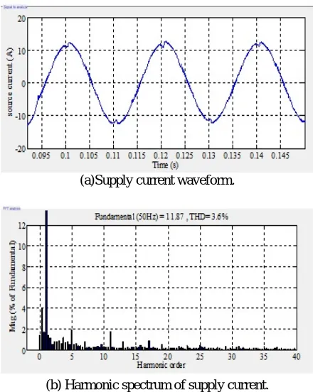
[image:4.612.317.538.99.373.2]The simulated system is a three phase balanced voltage system, the nonlinear load used in this work is a three phase non controlled bridge rectifier. THD without APF =25.91%. The test steady state operation is to assess if the controllers perform well under steady conditions. Figure-5 illustrate the system voltage. The grid current and its spectrum analysis before compensation are shown in Figure-6.After the connection, the source current THD is 4.15% with Conventional method PI as shown in Figure-7, and 3.6% with PSO-PI as shown in Figure-8. The source current becomes sinusoidal nearly instantaneously, as seen in Figure-8. The voltage of DC link capacitor can be seen in Figure-9.
Figure-5. Supply voltage waveform.
(a)Supply current waveform.
[image:4.612.74.296.291.694.2](b) Harmonic spectrum of supply current
Figure-6. Supply current waveform and its spectrum
without compensation.
(a)Supply current waveform.
[image:4.612.76.293.291.387.2](b) Harmonic spectrum of supply current.
Figure -7. Supply current waveform and its spectrum with
PI in steady-state case.
(a)Supply current waveform.
(b) Harmonic spectrum of supply current.
Figure-8. Supply current waveform and its spectrum with
[image:4.612.317.537.432.708.2]Figure-9. DC Link capacitor voltage after compensation in steady-state case.
The PI-PSO controller is the best controller as it achieves satisfactory performances, minimal rise time and less overshoot compared with classical PI. To control the SAPF, the particle swarm optimization (PSO) is used in this study to optimize the gains of a proportional-integral (PI) algorithm and the optimized gains obtained are: KP=
0.6284 and KI= 29.774.
Transient condition
When the load current is suddenly doubled, the change occurs at t = 0.5s. This test is used to demonstrate the flexibility of the filter to operate even when the load active power changes.
Before the connection APF, and due to the variation of the load the source current has a THD of 23.77% at 0.6s for three cycles as shown in Figure-10.
Figure-10. Supply current waveform before compensation
in transient case.
After compensation the supply current waveform as shown in Figure-11. THD of the source current by using PSO-PI was 3.6 % and has changed to 3.83 %, while by using conventional PI method the THD was 4.15% and has changed to 4.44 %. The variation of the voltage of DC link capacitor which occurred after load variation can be seen in Figure-12.
Figure-11. Supply current waveform after compensation
due to the variation of the load.
It is clear that the capacitor voltage follows its defined reference with fluctuation dependent on the power exchange between the grid and SAPF. The DC load current are shown in Figure-13. The load variation causes the change of the THD as shown in Figure-14.
Results show that both methods are capable of recovering from the sudden power increase and the THD values of these currents after compensation were all less than 5%. From analysis, it has been found that PSO-PI technique proves to be effective in reducing the THD of the source current. Figure-14 showing the comparison of THD with Conventional PI controller and with PI-PSO Controller due to the load change.
Figure-12. DC link capacitor voltage due to the variation
of the load.
Figure-14. THD due to the load change.
CONCLUSIONS
The control of SAPF based on PI controllers in three-phase system has been studied and discussed. The dq reference theory was used in harmonic current extraction. The grid current is sinusoidal with short time transient follows the load variation. PI controllers have been used for the control of filter currents and its DC voltage.
A PSO-based algorithm was developed to search for the optimal solution. The numerical results of case studies comparing the PSO method and the conventional method are reported. The PSO technique is found to offer better harmonic compensation and dynamic response under transient conditions. DC voltage of SAPF proves the efficiency of PSO-PI voltage controllers in the control of the capacitor voltage. It was noticed from the results that the DC voltage converges again to its reference which prove the efficiency of the controllers. The simulation results shows that it offers a very good performance and stability. The three phase grid currents are balanced and sinusoidal with perfectly reduced harmonic contents.
REFERENCES
[1] Izhar M., Hadzer C. M., Masri S. and Idris S. 2003. A study of the fundamental principles to power system harmonic. In: National Power and Energy Conference (PECon) 2003 Proceedings, Bangi, Malaysia pp. 225-232.
[2] Patnaik S. S. and Panda A. K. 2013. Real-time performance analysis and comparison of various control schemes for particle swarm optimization-based shunt active power filters. International Journal of Electrical Power & Energy Systems. 52:185-197.
[3] Dey, P., and Mekhilef, S. 2014. Synchronous reference frame based control technique for shunt hybrid active power filter under non-ideal voltage. In Innovative Smart Grid Technologies-Asia (ISGT Asia). pp. 481-486.
[4] Abu Hasim, A. S., Talib, M. H. N., and Ibrahim, Z. 2012. Comparative study of different PWM control scheme for three-phase three-wire shunt active power filter. In Power Engineering and Optimization Conference (PEDCO). Melaka, Malaysia, 2012 IEEE International, pp. 119-123.
[5] Patnaik S. S. and Panda A. K. 2014. Optimizing current harmonics compensation in three-phase power systems with an Enhanced Bacterial foraging approach. International Journal of Electrical Power & Energy Systems, 6: 386-398.
[6] M. T. Esfahani, S. H Hosseinian and B. Vahidi. 2015. A new optimal approach for improvement of active power filter using FPSO for enhancing power quality. International Journal of Electrical Power Energy Systems, 69: 188-199.
[7] Tsengenes, G. and Adamidis G. 2010. An improved current control technique for the investigation of a power system with a shunt active filter. In: Power Electronics Electrical Drives Automation and Motion (SPEEDAM). International Symposium on .pp. 239-244.
[8] Patnaik S. S. and Panda A. K. 2011. Performance improvement of id-iq method based active filter using particle swarm optimization.Chennai and Dr. MGR University Second International Conference on Sustainable Energy and Intelligent System (SEISCON 2011). Tamil Nadu, India. 20-22 July.pp.320-325.
[9] Pawar N., Patidar R. D. and Patidar L. C. 2012. An optimal controller for APF for customer harmonics and reactive power compensation. In: Engineering and Systems (SCES). 2012 Students Conference on. pp. 1-6.
[10] http://www.deltaww.com/Products/CategoryListT1.as px?CID=060502&PID=458&hl=enUS&Name=APF2 000.
[11] Singh R., Singh A. K., and Kumar P. 2011. Comparison of three evolutionary algorithms for harmonic mitigation using SAPF. In: Industrial and Information Systems (ICIIS).6th IEEE International Conference on. pp. 392-397.
[12] Bangia S., Sharma P. R., and Garg M. 2012. Design of optimal pi controller using particle swarm optimization for power quality. Proceeding of the National Conference “Science in Media 2012”. Organized by YMCA University of Science and Technology. Faridabad, Haryana (India) December 3rd-4th 2012. pp. 112-117.
Filter Design. In: Computer Modeling and Simulation. EMS'09: Third UKSim European Symposium on. pp. 395-399.
[14] J. Vijayasree, B. Vijayakrishna and Y. Rajesh Babu. 2012. Implementation of SRF based Multilevel Shunt Active Filter for Harmonic Control. International Journal of Engineering Research and Development. Vol. 3 No. 8, pp. 16-20.
[15] Fereidouni A. and Masoum M. A. 2014. Enhancing performance of active power filter with fuzzy logic controller using adaptive hysteresis direct current control. In: Power Engineering Conference (AUPEC). Australasian Universities. pp. 1-6.
[16] K. Latha, V.Rajinikanth and P. M. Surekha. 2013. PSO-based PID controller design for a class of stable and unstable systems”. Hindawi Publishing Corporation ISRN Artificial Intelligence. Vol. 2013, 11 pages.