2017 International Conference on Computer Science and Application Engineering (CSAE 2017) ISBN: 978-1-60595-505-6
Simulation Analysis of Efficiency of Wireless Power
Transmission System for AUV
Zaiyi Wang, Haokun Chi*, Zhiqiang Wei, Bo Yin and Yanping Cong
Department of Information Science and Engineering, Ocean University of China, 265100 Qingdao, China
ABSTRACT
Adequate electrical energy can guarantee long-term navigation for the autonomous underwater vehicle (AUV). Compared with the traditional wired charging method, wireless charging has the advantages of high security, simple operation and so on, and is more suitable for underwater application. In this paper, we study the efficiency of wireless power transmission (WPT) system in air and seawater. The transmission efficiency of wireless transmission system in air and seawater is compared with HFSS simulation. The reason of system efficiency decay is analyzed, which is helpful for the application of wireless power transmission technology in AUV.
INTRODUCTION
The vast majority of the earth is the sea, and the ocean contains a wealth of resources, how to detect, develop, use these resources has been the focus of research around the world. Artificial detection has the disadvantages of highly dangerous, high cost, and not persistent, while the AUV can solve these problems. In the case of sufficient power, AUV can continue to work in the sea. What’s more, it has the advantages of high security, strong concealment, low cost, simple recovery and so on. Therefore, how to ensure power supply for the AUV is one of the keys to AUV. When the electromagnetic wave propagates in the sea water, it will produce eddy current loss, which will affect the efficiency of wireless energy transmission system. In this paper, HFSS simulation software is used to compare the working efficiency of the same coil in air and sea water. On this basis, the influence of transmission distance on the efficiency is studied.
increasing the input voltage can increase the efficiency of the system. Using his method, when the output power reaches 500 W, the efficiency can exceed 94% [3]. Li studied the influence of seawater pressure and noncoaxial alignments of transmission units on the transmission efficiency. The results show that the maximum efficiency of the electromagnetic coupler in the brine can reach 90%, and its transmission power can reach 400 W[4]. Hu uses a kind of the negative permeability metamaterials to optimize the system and proposes a new impedance matching method to improve the efficiency of underwater wireless power transmission system. The experimental results show that the average efficiency of the proposed method is able to reach as high as 53%[5]. There are some other people who have made some wireless energy transmission solutions, and they all have achieved good results[6-10]. In this paper, We have simulated efficiencies of the system in the air and seawater and compared them.
EFFICIENCY CALCULATION OF WPT SYSTEM Transmission Efficiency of WPT System in the Air
In general, in order to improve the transmission efficiency of the WPT system, the inductive reactance in the circuit should be minimized, and the inductive inductance in the circuit can be compensated by the series or parallel capacitor at both ends of the inductor. The appropriate matching capacitors can make the coils in a resonant state. When the coil is in a resonant state, the inductive reactance is zero.
When the transmitter circuit is compensated in series and is in resonant state, the voltage on the series compensation capacitor is offset from the sense voltage drop and the voltage requirement for the power supply is reduced. When using parallel compensation, the current flowing through the parallel compensation capacitor compensates for the reactive component of the current in the primary winding, thereby reducing the current requirement for the power supply; and the current does not flow through the switch tube and only within the resonant network. Therefore, in the case of the need for large current, the transmitter circuit parallel compensation method can greatly reduce the current in the inverter circuit switch pressure.
the output power of the load will be greatly improved. In the case of battery charging, the parallel compensation method should be used to achieve the constant current charging the battery.
Through the above analysis, we can see that the series, parallel resonant compensation can be equivalent to the voltage source, current source respectively. Considering the application of seawater scene, in this paper we only study the system efficiency of the compensation structure (Figure 1) of transmit circuit parallel - receive circuit in parallel (PP-SP).
+ -U1 C1 R1 L1 L2 R2 C2 RL + -U1 C1 R1 L1 Zr
Figure 1. PP-SP. Figure 2. Equivalent Circuit.
In order to calculate the efficiency expediently, we put the receiver circuit equivalent to a resistance of the launch circuit (Figure 2), so the efficient is:
2 12 2
in 1
= L = r 100%
in P i Z P i Z
(1)
Where PL and Pin are represented separately receive power of Load RL and the
total input power of the power, i12 is the current flowing into Zr, is the ratio of the
power consumed by load resistance RL to the total power of the receiving circuit;
when the receiving circuit adopts the parallel compensation, there is:
* 2
2 2 2
* 2
2 2 2
(1 )
(1 )
PAR
L L
R Q R
R R Q R R
(2)
When both the transmitting and receiving circuits adopt the parallel structure, the parallel LC network impedance equivalent transformation is used on both sides. The derivation transmission efficiency is:
2 2 2 2
12 1 1 2 2
2 2 2 2
1 1 1 1 1 2 2
2 2 2 2 2
2 2
2 2 2 2 2 2 2 2 2 2 2
2 2 2 2 2 1 2 2 2
(1 ) Re( ) Re( ) (1 )
=
(1 )[ Re( )] Re( ) (1 )
( )
100%
( )( ) ( )
r PAR r PAR r
in r r L
L
L L L
i Z i Q Z Z Q R
i Z i Q R Z R Z Q R R
M R R L
M R R L R L R R R R L R R
(3)
Transmission Efficiency of WPT System in the Seawater
can be regarded as an impedance parallel to the primary and secondary coils. When the WPT system is working in the seawater environment, the loss on the circuit and coil remains unchanged compared with the situation in the air, an additional increase in the eddy current effect of the power loss, but the loss increases due to the eddy current effect. Thus, the power obtained by the load in the seawater is the difference between the power obtained in the air and the power generated by the eddy current:
seawater air eddy
P P P (4)
Where, Pseawater and Peddy represent the power obtained by the system load and
the power loss of the eddy current in the seawater, respectively. Pair represents the
transmission efficiency of the system in the air. The transmission efficiency of the system in the air is defined as the ratio of the power obtained by the load to the total power of the power input:
= air 100% tatal circuits coils 100%
air
tatal tatal
P P P P
P P
(5)
Therefore, in the case of constant input power, the system transmission efficiency in the seawater is:
100%
100% 100%
tatal circuits coils eddy seawater
tatal
air eddy eddy air
tatal tatal
P P P P
P
P P P
P P
(6)
HFSS SIMULATION ANALYSIS
In this part, we use the three-dimensional electromagnetic simulation software HFSS to simulate the power transmission efficiency of WPT system in air and sea water respectively, and study the influence of transmission distance on system efficiency in two kinds of media.
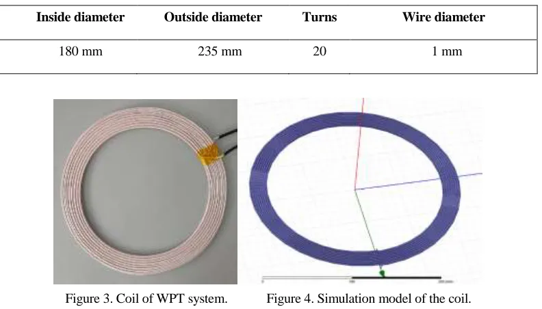
TABLE I COIL PARAMETERS.
Inside diameter Outside diameter Turns Wire diameter
180 mm 235 mm 20 1 mm
Figure 3. Coil of WPT system. Figure 4. Simulation model of the coil.
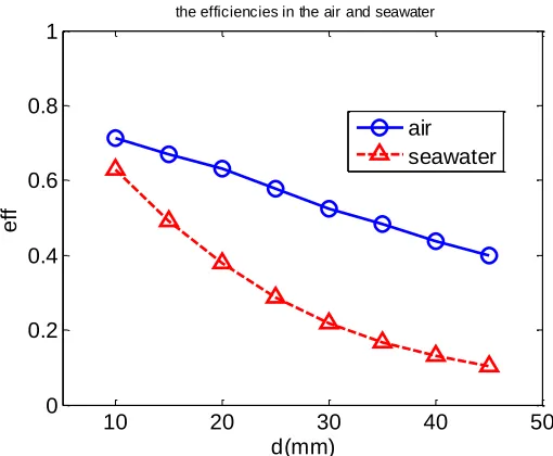
[image:5.612.159.435.498.648.2]From the simulation results we can see that with the increase of transmission distance, the transmission efficiency of the system is gradually reduced, that is because as the distance increases, the coupling coefficient between the transmission coil decreases, resulting in the reduction of efficiency. At the same time, we can find the efficiency of the system in the seawater is lower than that in the air at the same transmission distance, which is due to the loss of the eddy current effect of the seawater. What’s more, the decay rate of efficiency is faster in the seawater, while gentle in the air. This is because when the transmission distance increases, the eddy current loss of seawater plays a leading role. However, when the distance increases to a certain extent (greater than 30 mm in this paper), the reduction of the coupling coefficient becomes the main factor affecting the efficiency.
Figure 6. Emulation efficiencies in the air and seawater.
CONCLUSIONS
In this paper, the effect of eddy current loss of seawater on the efficiency of wireless power transmission system is studied. The transmission efficiency in the air and sea water at different distances is simulated respectively. The results show that transmission efficiency in seawater is lower and attenuation is faster. Therefore, in practical application, we should minimize the transmission distance of underwater wireless transmission system, reduce the seawater between the two transmission units by docking or other ways, in order to achieve the purpose of improving transmission efficiency.
ACKNOWLEDGMENT
This paper received funding from Qingdao innovation and entrepreneurship leading talent project (13-cx-2), Qingdao national laboratory for marine science and technology Aoshan science and technology innovation project (2016ASKJ07-4) and
China International Scientific and Technological Cooperation Special
(2015DFR10490).
REFERENCES
1. Yoshioka, Daisaburo, et al. 2007. "Power Feeding and Data-Transmission System Using Magnetic
Coupling for an Ocean Observation Mooring Buoy," IEEE Transactions on Magnetics, 43(6):2663-2665.
10 20 30 40 50
0 0.2 0.4 0.6 0.8 1
d(mm)
e
ff
the efficiencies in the air and seawater
2. Wang, Haiyang, et al. 2012. "Optimization of underwater contactless power transmission couplers,"
China Science paper, 48(3):73-87(15).
3. Shi, Jian Guang, L. I. De-Jun, and C. J. Yang. 2014. "Design and analysis of an underwater
inductive coupling power transfer system for autonomous underwater vehicle docking applications,"
Journal of Zhejiang University (English Edition), 15(1):51-62.
4. Li, Ze Song, et al. 2014. "Design considerations for electromagnetic couplers in contactless power
transmission systems for deep-sea applications," Journal of Zhejiang University (English Edition),
Computer and electronics, 11(1):62-62.
5. Hu, Yuli, et al. 2016. "Impedance matching control method for an underwater magnetic
resonance-based wireless power transfer system with metamaterials," Journal of Electromagnetic Waves & Applications, 30(15):1-17.
6. Mayordomo, Iker, et al. 2013. "An Overview of Technical Challenges and Advances of Inductive
Wireless Power Transmission," Proceedings of the IEEE, 101(6):1302-1311.
7. Amato, Massimiliano, et al. 2013. "Modeling, fabrication and characterization of micro-coils as
magnetic inductors for wireless power transfer," Microelectronic Engineering, 111(1):143-148. 8. Wu, K, D. Choudhury, and H. Matsumoto. 2013. "Wireless Power Transmission, Technology, and
Applications [Scanning the Issue]," Proceedings of the IEEE, 101(6):1271-1275.
9. Chung, Yoon Do, et al. 2015. "Design Consideration and Efficiency Comparison of Wireless Power
Transfer With HTS and Cooled Copper Antennas for Electric Vehicle," IEEE Transactions on
Applied Superconductivity, 25(3):1-5.
10. Miller, J. M, O. C. Onar, and M. Chinthavali. 2015. "Primary-Side Power Flow Control of Wireless
Power Transfer for Electric Vehicle Charging," Emerging & Selected Topics in Power Electronics