Parameter Estimation and Control of Induction
Machine using a new Recursive Algorithm
Nawel DAMAK and Samira KAMOUN
Laboratory of Science and Techniques of Automatic control and computer engineering (Lab-STA)
National School of Engineering of Sfax (ENIS),
University of Sfax, B.P. 1173, 3038, Sfax, Tunisia.
ABSTRACT
Two schemes control for induction machine are proposed and com-pared. A new off-line recursive algorithm is used to estimate the parameters of a commercial 1 kW induction motor, which is de-scribed by a multivariable state space mathematical model. The self-tuning control scheme and the control scheme with distur-bance compensation are proposed. Those techniques are based on the concept of quadratic optimal control. The schemes control per-formance is tested using stator current, voltage and speed measure-ments. The obtained results demonstrate the proposed schemes’s effectiveness.
Keywords:
Induction machine, Recursive algorithm, Off-line parameter es-timation, Control schemes
1. INTRODUCTION
The low maintenance costs, the robustness, the usability are advantages that characterize the induction machine. This latter is widely used in many industrial app-lications and currently there is an significant effort being done toward obtaining advanced induction machines [5], [6]. Control schemes of such motors require an accurate knowledge of at least some of the induction machine parameters. Any gap between the parameter values used within the controller and actual parameter values in the motor leads to a worsening in the drive performance.
A wide variety of modeling, signal processing, and control schemes have been developed to ensure that induction motors function reliably. Investigations that describe the scope of this existing research are presented in [7], [8]. The parametric estimation of the electric motors have widely integrated the optimization methods. Most of the estimation procedures use complex algorithms for the parametric estimation. The major difficulty behind the optimization techniques is the choice of the motor physical model and of the optimization algorithm.
The paper is organized in four sections. Next section presents the recursive parameter estimation algorithm. Section three was re-served to testing the proposed algorithm by application for an in-duction machine. Section for includes the self-adjusting control of induction machine. Sexion five presents the control scheme with disturbance compensation. Finally a brief conclusion is pre-sented in section six.
2. RECURSIVE PARAMETER ESTIMATION
ALGORITHM
Let us consider a linear multivariable system described by the following discrete-time state-space mathematical model:
x(k+ 1) = A(k+ 1)x(k) +B(k+ 1)u(k) +v(k)
y(k) = Cx(k) +e(k) (1)
where u(k) ∈ Rr, y(k) ∈ Rz and x(k) ∈ Rn represent the input vector, the output vector and the state vector of the system at the discrete timek. The matricesA(k+ 1),B(k+ 1) andCrepresent the state matrix, the command matrix and the measurement matrix, respectively,v(k)∈Rnis the noise vector which acts on the system,e(k)indicates the noise which affects the measurement of the outputy(k).
The parameter estimation problem of the dynamic multivariable system described as a state mathematical model is composed of an estimation procedural development that allows us to estimate the unknown parameters of theA(k+ 1)andB(k+ 1)matrices.
The formulation of this problem is based on experimental measurements (input and state sequences) originated in the considered system and minimizing a quadratic criterion com-prising the estimation error (also called prediction error), which is defined as:
δ(k) =x(k)−xp(k) (2)
withxp(k)the state vector of the adjustable model, as follows:
xp(k+ 1) =Ab(k+ 1)x(k) +Bb(k+ 1)u(k) (3)
whereAb(k+ 1) andBb(k+ 1)are the estimated matrices of
A(k+ 1)andB(k+ 1)at the discrete-timek+ 1, respectively.
For the estimation of the parameters of the two matricesA(k+ 1)andB(k+ 1)of the state-space mathematical model, This recursive parameter estimation algorithm, which is developed for multivariable systems, is used:
b
A(k+ 1) = Ab(k) +ξ(k)Rδ(k)xT(k−1)
b
B(k+ 1) = Bb(k) +ξ(k)Rδ(k)u
T (k−1)
ξ(k) = l(k)
λR[uT(k−1)u(k−1) +xT(k−1)x(k−1)]
wherel(k)is a positive parameter gain andλRis the maximum eigenvalue of the matrixR.
The analysis of the stability conditions leads to the following condition, which is related to the choice of the gain intervening in the algorithm (4):
1< l(k)<2 (5)
3. OFF-LINE PARAMETER ESTIMATION OF
INDUCTION MACHINE
In this section, the recursive algorithm which is presented in the previous section is applied to the estimation of the induction ma-chine’s parameters.
The induction machine is described by the following discrete-time state-space mathematical model:
x(k+ 1) = A(k+ 1)x(k) +Bu(k) +v(k) (6)
y(k) = Cx(k) +e(k)
whereu(k),y(k)andx(k)represent the input vector, the output vector and the state vector of the induction machine. These are defined by:
uT(k) = [uds(k) uqs(k) ] (7)
yT(k) = [ids(k) iqs(k) ] (8)
and
xT(k) = [ids(k) iqs(k) φdr(k) φqr(k) ] (9)
The state vector x(k) contains the stator currentsids(k) and
iqs(k)and the rotor fluxφdr(k)andφqr(k). The input and the output of the induction machine correspond to the stator voltage
uds(k)anduqs(k)and to the stator currentsids(k)andiqs(k), respectively.
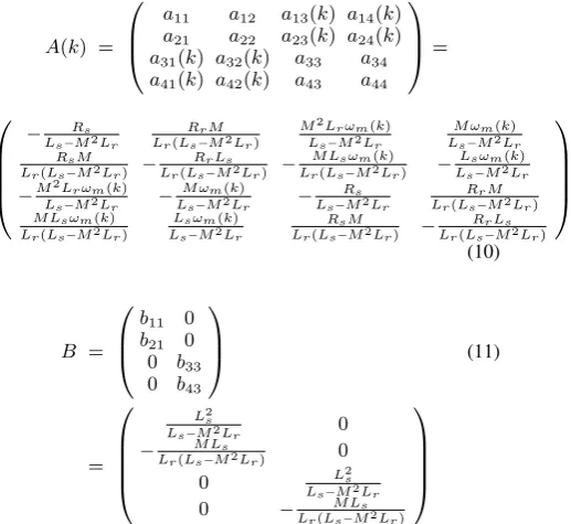
The matricesA(k),B andC are defined, respectively, by the following expressions:
A(k) =
a11 a12 a13(k) a14(k)
a21 a22 a23(k) a24(k)
a31(k) a32(k) a33 a34
a41(k) a42(k) a43 a44
=
− Rs
Ls−M2Lr
RrM Lr(Ls−M2Lr)
M2Lrωm(k)
Ls−M2Lr
M ωm(k)
Ls−M2Lr
RsM Lr(Ls−M2Lr) −
RrLs
Lr(Ls−M2Lr) −
M Lsωm(k)
Lr(Ls−M2Lr) −
Lsωm(k)
Ls−M2Lr −M2Lrωm(k)
Ls−M2Lr −
M ωm(k)
Ls−M2Lr −
Rs
Ls−M2Lr
RrM Lr(Ls−M2Lr)
M Lsωm(k)
Lr(Ls−M2Lr)
Lsωm(k)
Ls−M2Lr
RsM Lr(Ls−M2Lr) −
RrLs
Lr(Ls−M2Lr)
(10) B =
b11 0
b21 0
0 b33
0 b43
(11) = L2 s
Ls−M2Lr 0 − M Ls
Lr(Ls−M2Lr) 0
0 L2s
Ls−M2Lr
0 − M Ls
Lr(Ls−M2Lr) and C=
1 0 0 0 0 1 0 0
(12)
The parametersLs,Lr,M,RsandRrrepresent the stator cyclic inductance, the rotor cyclic inductance, the stator-rotor mutual cyclic inductance, the stator resistance, and the rotor resistance, respectively. The time-varying parameters of the matrixA(k+1) depend on the mechanical speedωm(k).
The parameter estimation problem of the induction machine, described as a state-space mathematical model, is composed of an estimation procedural development that allows us to estimate the unknown constant parameters and the unknown varying-time parameters, which are depending on the mechanical speed
ωm(k), of the matricesA(k+ 1)andB.
The evolution curves of the estimated parameters ˆa11(k),
ˆ
a12(k),ˆa13(k)andˆa14(k)are shown in Figures 1 and 2.
0 250 500 750 1000
0 0.1 0.2 0.3 0.4
0 250 500 750 1000
−1 0 1 2 3 ˆ
a12(k)
a12(k)
ˆ
a11(k)
a11(k)
[image:2.595.314.540.445.518.2]k k
Fig. 1. Evolution curves of the estimated parametersˆa11(k)and
ˆ
a12(k).
0 250 500 750 1000 −40
−30 −20 −10
0 250 500 750 1000 10
20 30 40
ˆ
a14(k)
a14(k)
ˆ
a13(k)
a13(k)
[image:2.595.57.316.547.784.2]k k
Fig. 2. Evolution curves of the estimated parametersˆa13(k)and
ˆ
4. SELF-TUNING CONTROL SCHEME
In this section, two control schemes, which can be applied to the considered induction machine, are developed. For the synthe-sis of an explicit self-adjusting control scheme of induction ma-chine, the recursive parameter estimation algorithm (4) is used. To calculate the control, the following quadratic criterion is min-imized:
J(k) =1 2
∞
X
0
xT(k)Qx(k) +uT(k)Gu(k)
(13)
whereQandGrepresent positive definite matrices.
The contol which minimizesJ(k)is the following:
u(k) =−Kx(k) (14)
whereKis the matrix, which is given by:
K= [R+BTP B]−1BTP A (15) The positive definite matrixP is the solution of the following Ricatti equation:
ATP A−P−ATP B[R+BTP B]−1BTP A+Q= 0 (16) The steps of the self-adjusting control, using an explicit scheme, are the following:
(1) step 1: estimate the parameters involved in the matricesA
andBof the state model (6), using the recursive algorithm (4);
(2) step 2: determine the matrixK, using the estimated matrices ˆ
AandBˆ;
(3) step 3: determine the controlu(k), from equation (14).
The evolution curves of the estimated parameters, the compo-nents of the controlu(k), state variables of the induction ma-chine and the chosen speeds as references are given in Figures 3, 4, 5, 6 and 7.
0 250 500 750 1000 0
0.1 0.2 0.3 0.4
0 250 500 750 1000 0.8
0.9 1 1.1 1.2 ˆ
a11(k) ˆa12(k)
[image:3.595.313.540.88.330.2]k k
Fig. 3. Evolution curves of the estimated parametersˆa11(k)and
ˆ
a12(k).
0 250 500 750 1000 0.5
0.6 0.7 0.8 0.9
0 250 500 750 1000 −0.04
−0.03 −0.02 −0.01 0 ˆ
a21(k) ˆa22(k)
[image:3.595.316.540.216.318.2]k k
Fig. 4. Evolution curves of the estimated parametersˆa21(k)and
ˆ
a22(k).
0 250 500 750 1000 0.4
0.6 0.8 1 1.2
0 250 500 750 1000 −1
−0.8 −0.6 −0.4 −0.2 ˆ
b11(k) ˆb21(k)
[image:3.595.317.540.355.443.2]k k
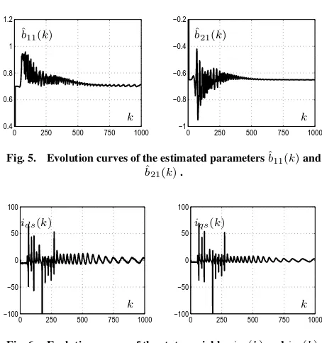
Fig. 5. Evolution curves of the estimated parametersˆb11(k)and
ˆ
b21(k).
0 250 500 750 1000 −100
−50 0 50 100
0 250 500 750 1000 −100
−50 0 50 100
ids(k) iqs(k)
[image:3.595.56.280.526.610.2]k k
Fig. 6. Evolution curves of the state variablesids(k)andiqs(k).
0 250 500 750 1000 −10
5 20 35 50
0 250 500 750 1000 −40
−20 0 20 40
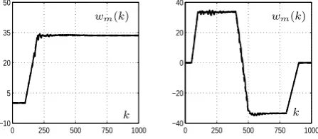
wm(k) wm(k)
k k
Fig. 7. Evolution curves of the two types of speed refe-rence.
Examining Figures 3, 4 and 5 and based on knowledge of the numerical values of the estimated parameters, the quality of es-timation of the induction machine is good. The real values of some simulated parameters are :a11 = 0.22, a12 = 0.98et
a21 = 0.73. Therefore, the estimated values, based on the
fig-ures, are close to the real values.
Concerning the speed reference, the controlu(k)allows the esti-mation algorithm to follow both types of imposed reference sig-nals. So, this control scheme has assured good performance.
5. CONTROL SCHEME WITH DISTURBANCE
COMPENSATION
In this section, a control schemes is developed, which compen-sates disturbance. A dynamic system is considered. This system is affected by a disturbancev(k), which is described by the fol-lowing state space model:
x(k+ 1) =A(k)x(k) +B(k)u(k) +v(k) (17)
wherex(k)andu(k)represent respectively the vector state vari-able and the control law of the system at discrete timek. The controlu(k)is seeked. This control minimizes the following criterion:
J(k) = 1 2
k=n
X
k=0
xT(k)Qx(k) +uT(k)G(k)u(k) (18)
[image:3.595.55.280.650.735.2]ˆ
A(k)x(k) + ˆB(k)u(k) +v(k). The Lagrangien then reads:
L(k) = k=n
X
k=0
(1 2x
T
(k)Q(k)x(k) +1 2u
T
(k)R(k)u(k)
(19) +pT(k+ 1)(−x(k+ 1) + ˆA(k)x(k)
+ ˆB(k)u(k) +v(k)))
The optimum solution satisfies the following equation:
∂L
∂u(k) = R(k)u(k) + ˆB
T(k)p(k+ 1) = 0 (20)
∂L
∂x(k) = Q(k)x(k)−p(k) + ˆA
T(k)p(k+ 1) = 0(21)
and
∂L
∂p(k+ 1) =−x(k+ 1) + ˆA(k)x(k) + ˆB(k)u(k) +v(k) = 0 (22)
The equation for the control (20) gives:
u(k) =−R−1(k) ˆBT(k)p(k+ 1)
(23)
Replacing the control (23) in the (22) and by taking (21), a sys-tem of equations is obtained, whose unknown signals arex(k) andp(k):
Qx(k)−p(k) + ˆAT(k)p(k+ 1) = 0 (24)
−x(k+ 1) + ˆA(k)x(k)−Bˆ(k)R−1(k) (25) ˆ
BT(k)p(k+ 1) +v(k) = 0
Using equations (24) and (25), the adjoint state can be calculated
p(k)in each discrete timekby the following recurrent equation:
p(k+ 1) = ( ˆA(k)T)−1[[ ˆB(k)R−1(k) ˆB(k)]−1 (26)
[−x(k) + ˆA(k)x(k−1) +v(k)]−Qx(k)]
Using the control (23) in the algorithm (4). The evolution curves of the speeds choosen selected as references are given in Figure 8.
0 250 500 750 1000
−10 5 20 35 50
0 250 500 750 1000
−40 −20 0 20 40
wm(k) wm(k)
[image:4.595.56.280.548.646.2]k k
Fig. 8. Evolution curves of the two types of speed reference.
By comparing the curves for speed reference obtained using the command (14) and control with disturbance compensation (23), the quality of estimation is improved.
6. CONCLUSION
In this paper, a recursive parameter estimation algorithm and two control schemes, which can be applied to an induction machine, are developed. By means of the stator voltage and currents mea-surements, the recursive algorithm is applied to estimate the pa-rameters of induction machine which is described by state-space
mathematical model. The obtained results show the effectiveness of this algorithm on the convergence of the estimated parameters towards the real one. The quadratic optimal control is applied to the induction motor. The figures of the estimated parameters show good performance of the self-adjusting control. Tracking speeds reference of the induction motor is improved, using a con-trol law which compensates disturbance.
7. REFERENCES
[1] S.R, Shaw and S.B. Leeb: Identification of induction mo-tor parameters from transient stamo-tor current measurement. IEEE. Ind. Electron, 46 (1), pp. 139-149, 1999.
[2] Y. Koubaa: Recursive identification of induction motor pa-rameters. Simulation Modelling Practice and Theory, 12 (5), pp.363-381, 2004.
[3] Y. Koubaa: Asynchronous machine parameters estimation using recursive method. Simulation Modelling Practice and Theory, Vol. 14, pp.1010-1021, 2006.
[4] N. Damak, S. Kamoun and Y. Koubaa. Estimation of asyn-chronous machine parameters and state variables. Interna-tional Review on Modelling and Simulations (IREMOS), vol. 4, pp. 1112-1120.
[5] A. Szumanowski: Fundamentals of hybrid vehicle drives. Publishing and Printing House of the Institute for Sustain-able Technologies NRI, Warsaw-Radom. Vas P. 1990. Vec-tor control of AC machines. Clarendon Press, Oxford UK, 2000.
[6] M. Ehsani, Gao J., Sebastien E. and Gay E., Emadi A: Modern electric, and hybrid electric, and Fuel Cell Vehi-cles. Fundamentals, theory, and design. CRC Press, Lon-don, New York, Washington.
[7] H. Toliyat, E. Levi, and M. Raina. SA review of RFO induction motor parameter estimation techniques. IEEE Transactions on Energy Conversion, vol. 18, no. 2, pp. 271283, Jun. 2003.
[8] P. Vas: Parameter Estimation, Condition Monitoring, and Diagnosis of Electrical Machines. Clarendon Press, 1993. [9] T. Matsuo and T.A. Lipo: Rotor Parameter Identification
Scheme for Vector Controlled Induction Motor Drives. IEEE trans. On Ind. Appl. Vol. IA-21, n3. pp 624-632, 1985.
[10] Moazzam, M.; T. Hesketh, and D.J. Clements: Recursive identification of certain structured time-varying state-space models. IEE Proc. Control Theory Appl, Vol. 144, No5, 1997.
[11] M. Hilairet; F. Auger and E. Berthelot: Speed and rotor flux estimation of induction machines using a two-stage ex-tended Kalman filter. Automatica, Vol. 45, pp. 1819-1829, 2009.
[12] F. Ding and T. Chen: Hierarchical least squares identifica-tion methods for multivariable systems. Automatic control, IEEE Transactions on, Vol. 50, pp. 397-402, 2005. [13] I.D. Landau: Evolution of adaptative control. A.S.M.E.
Transactions, Journal D.S.M.C, Vol. 115, pp. 381-391, 1993.
[14] N. T.West and R. D. Lorenz: Digital implementation of sta-tor and rosta-tor flux-linkage observers and a stasta-tor-current ob-server for deadbeat direct torque control of induction ma-chines. IEEE Transactions on Industry Applications, vol. 45, no. 2, pp. 729736, 2009.
[16] A. Musolino, R. Rizzo, and E. Tripodi: Tubular linear in-duction machine as afast actuator: Analysis and design cri-teria. IEEE Progress In Electromagnetics Research, Vol. 132, 603-619, 2012.
Authors’s Profile
Nawel Damak She was born in Sfax , Tunisia in 1981. She received the B.S, master and Phd degrees in 2005, 2007 and 2012 respectively, from the National School of Engineering of Sfax (ENIS), all in Electrical Engineering (Automatic and in-dutrial computing). She has authored several papers in interna-tional conferences and technical journals. Her research interests include identification and adaptative control of systems (multi-variable systems, time-varying systems, stochastic systems) with application to electrical machine.