An Efficient Approach for Automatic Cloth Panel
Extraction from Pattern Images
KhaledF. Hussain
Faculty of Computers and Information, Assiut University,
Assiut, Egypt
Samia A. Ali
Department of Electrical Engineering, Faculty of Engineering,
AssiutUniversity, Assiut, Egypt
SaherM.Malek
Faculty of Engineering, Assiut University,
Assiut, Egypt
ABSTRACT
Producing 3D cloths for different body sizes from 2D patterns of any size has recently gained attention in both academic and industry fields. Most of the classical patterns in old books and magazines are available only in hardcopy forms. Thus, there is a need to produce softcopies of those patterns in the old books and magazines. In this research work, efficient solutions for these two issues are provided. First, a specific pattern size given any size pattern is automatically generated. This greatly facilitates the generation process of different size patterns in the apparel industry. Second, the design of customized apparel products provided in hardcopy images is fully automated. This automation process can greatly improve the efficiency of cloth production in the apparel industry.
General Terms
Pattern recognition, Virtual reality
Keywords
Garment industry, 3D clothes, Cloth modeling
1.
INTRODUCTION
The desire of getting softcopies of old patterns found in hardcopy forms in books and magazines has been considered a critical issue and need to be solved efficiently. Furthermore, the problem of obtaining 3D cloths for different body sizes from 2D patterns of a specific size requires fast and accurate solutions. Moreover, the pattern generation process is considered to be a bottleneck for the garment manufacturing, especially for producing different size garments for the same style patterns [1].
In the literature, three methods are available for modeling of virtual cloths: The first method [2] is using the traditional approach to produce real cloth through drawing the 2D panels. This approach requires a skillful pattern-maker for the 2D panel drawing. The second method [3] is producing the 2D sketch based on 3D features of the character model. This approach is efficient for simple clothes, but it is hard to use for complex ones. The third method [4] is designing clothes in 3D by modeling 2D mesh cloth around the character model. This approach requires an intensive labor to modify the size of the cloth model to fit different character models. There are many challenges in the garment production industry that are related to the different features of customers in order to produce maximally conformable garments. Thus, it is very important for the clothdesigners and manufacturers to know information about human body outer shape description, sizing and measurements. Currently the most important challenge for the clothing industry is the improvement on the basic stage of the designing process [5]. Also, it is important to know the
3-D tools that might be used in the garment design to improve the efficiency of pattern generation and producing a more attractive design presentation.
The classical patterns in old books and magazines are available only in hardcopy forms. Therefore, it is desirable in some instances to produce softcopies of those patterns in the old books and magazines. It is of some practical interest to produce 3D cloths for different body sizes from 2D patterns of any given size. In this work, efficient solutions to solve these two problems are introduced. More specifically, external boundary detection and dart detection techniques are used to automatically extract panels from pattern images. Furthermore, for a specific given panel, a cubic Bezier curve representing the panel is generated. Then, alinear conformal transformation and/or affine transformation are used to generate the panel with the desired size. Thus, the two proposed techniques can greatly improve the efficiency of cloth production in the apparel industry.
The rest of this paper is organized as follows. Section 2 summarizes the related work to the proposed research. Section 3 introduces the proposed reliable approach for automatic panel extraction. Resizing panel is presented in Section 4. Developed software and the results are reported in Section 5. Finally, conclusions of this research work are shown in Section 6.
2.RELATED WORK
intensive labor. Modifying the size of the cloth is required in many applications such as online clothing shops.
The current proposed research work has two main contributions; one is the automatic extraction of cloth panels from pattern images, while the other is the generation of different cloth sizes for different character models from a single given size pattern. The proposed research work relied on three image processing techniques: snakes, curve representation, and transformations. Active contours, or snakes, are used widely in the literature to find object boundaries. Curve representations are used to draw panels which consist mainly of curves. Transformation techniques have become very popular and important in image processing. Transformation is used in deforming the panels.
Active contours, or snakes, are curves defined within an image domain that can move under the influence of internal forces coming from within the curve itself and external forces computed from the image data [7]. They are often used in computer vision and image processing techniques to detect and locate objects, and to describe their shapes. For example, a snake might be used to automatically find a manufactured part on an assembly line, the outline of an organ in a medical image, and the outline of a pattern in this work. There are two well-known types of snakes, the traditional snake and the gradient vector flow (GVF) snake. In this paper, the gradient vector flow (GVF) snake is used. The advantages of the GVF snake over the traditional one are its insensitivity to initialization and its ability to move into boundary concavities. Its initializations can be inside, outside, or across the object’s boundary.The gradient vector flow (GVF) snake begins with the calculation of field of forces, called the GVF forces, over the image domain. The GVF forces are used to drive the snake, modeled as a physical object having a resistance to both stretching and bending, towards the boundaries of the object. The GVF external forces make the GVF snake inherently different from the previous snakes. The GVF forces are derived from a diffusion operation, thus they tend to extend very far away from the pattern.
Curves are normally used to draw panels. A curve can be as simple as a line or as complex as a B-Spline. In general, Curves can be classified as follows:
I- Analytical curves: This type of curves can be represented by a simple mathematical equation, such as, a circle or an ellipse. They cannot be used to represent curves of patterns because of their complex shapes.
II- Interpolated curves: They are drawn by interpolating the given data points and have fixed forms which are dictated by the given data points. These curves cannot be used to represent curves of the pattern because they are hard to edit, have limited flexibility, and needing a large number of data points.
III- Approximated curves: These curves provide the most flexibility in the drawing of complex shapes. There are many types of approximated curves such as Bezier and B-spline. These curves can be joined together to form a smooth curve, and local changes in the shape do not affect the entire shape of the curve [8].
Bezier curves are most often used in a number of applications due to their flexibility in forming curves. Bezier curves differ from other types of parametric curves by the type of basis polynomials used to form them [9].Bezier curves are now widely used in many fields such as industrial and computer-aided design, vector-based drawing, font design and 3D modeling. The Bezier curve of the third order is the most commonly used and it is fully defined by four points: two endpoints (P0, P3) and two control points (P1, P2). The control
points do not lie on the curve itself, but they define its shape.
Thereare many properties of Bezier Curves such as endpoint interpolation, convex hull property, and prescribed tangent lines at the endpoints.
Transformation is mainly a function that creates images which are congruent to the original image. There are many types of transformations in the literature such as linear conformal transform, box transformation, composite transformation, projective transformation, polynomial transformation, LWM transformation (local weighted mean), piecewise transformation, custom transformation, and affine transformation [10]. The affine, linear conformal, projective, and polynomial transformations are global transformations. In these types of transformations, a single mathematical expression applies to an entire image. However, the piecewise, and LWM (local weighted mean) transformations are local transformations. In these transformations, different mathematical expressions apply to different regions within an image. In this research work, linear conformal transformation and affine transformation are used. The affine transformation is a mixture of scaling, rotation, shearing, and translation processes. Straight lines remain straight and parallel lines remain parallel to avoid distortion of the main features of the pattern. The affine transform requires at least three pairs of control points. On the other hand, linear conformal transform is a mixture of scaling, rotation, and translation processes. Thus linear conformal transform requires at least two pairs of control points.
Due to the importance of virtual clothing for the cloth design industry, computer generated movies and games, thus cloth simulation is needed. Cloth simulation is one of the main subjects in computer animation that recently gained attention in the literature [11-17]. Early cloth simulations focused on generating the geometrical features of clothes [18].With the fast advance in technology of graphic cards and computers’ processing power, an accurate generation of movement of clothes has been achieved, using particle systems [15, 16] or finite elements [19]. The modeling of virtual cloths requires special tailoring skills.
3.
AUTOMATIC PANEL EXTRACTION
In this section, a novel reliable approach for automatic panel detection based on image processing techniques from pattern images is presented. The proposed approach consists of two main stages: automatic external boundary detection and automatic dart detection.
To detect external boundaries of panels from pattern images, the next steps are followed:
1- Given an input gray pattern image , the input image is converted to gray level, if the input image is a color image.
2- The grayscale image is converted into a binary image and the connected components
)
are computed for the binary image.3- For each connected component,a panel or a non-panel (e.g., arrows and words) test is performed. Then the width, height, and area of the connected component are computed.If the width is less than a threshold value , the height is less than a threshold value , or the area is less than a threshold value , the connected component is considered a non-panel.
number is equal to zero, this means that applying the boundary trace algorithm produces an incorrect result. Thus, the snake technique is used in this case.
5- The snake based on Gradient Vector Flow (GVF) [7] is applied to extract the correct boundary of the panel. The snake is used to fit closed curves which is usually the case in cloth panels. The input to the snake is the boundary that is computed in the previous step. Then the snake is attracted towards the boundary of the panel by forces called gradient vector flow (GVF).
The gradient vector flow field is defined as
which minimizes the energy ε.
ε is defined as follows:
v (1)where the
coefficient µ specifies the relative importance of the first term versus the second term and .
Equation (1) can be rewritten in the following general form:
(2)
which has the following general solution that is represented by the two Euler equations:
. (3)
The general solution in (3) can be applied to the specific problem in (1) as follows:
. (4)
The iterative solution to the equations in (4) is:
(5)
Where , ,
, and .
The boundary is defined as a parametric curve
, where s is the arc length. The final
position of the boundary minimizes the energy, :
(6)
where , , and
. Thus,
(7)
The energy is defined as the sum of three energy terms: (1) is the continuity term which is responsible for the shrinking of the contour. (2) is the smoothness term which is used to smooth the curve. (3) is an edge attraction term to attract
the contour towards the boundary of the panel.
The solution of equation (7) that minimizes the snake’s energy must satisfy the Eular equation
(8)
Where , is calculated in equation (5). To solve
equation (8), the contour c(s) is consider as a function of time, i.e., c(s,t)
(9)
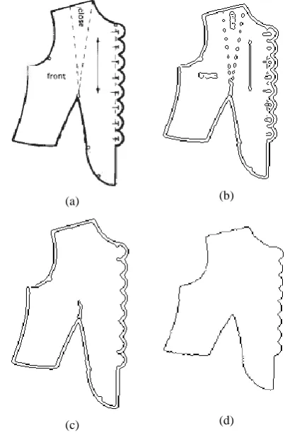
Equation (9) can be solved iteratively until . The result is the boundary points . Figure 1(d) shows the boundary after applying the snake technique.
(a) (b)
(c) (d)
Fig. 1: (a) The original scanned pattern. (b) The image after applying the canny edge detection to the panel in image (a). (c) Incorrect boundary trace. (d) The boundary
after applying the snake technique.
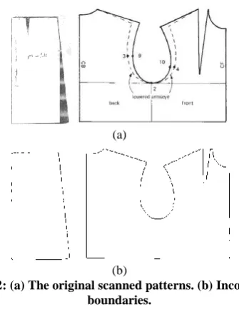
Applying the previous steps to a panel having darts will produce an incorrect boundary as shown in Figure 2. To remedy this problem, the darts are automatically detected and insertedintothe detected boundary in the previous steps.Morespecifically,the exterior boundary is traced for each panel, as well as the boundaries of the interior inside this panel , in the binary image, as shown in Figure 3.For each interior boundary BI, let be the set of the points of the .For each point , a test is performed tocheck whether it is a dart’s corner or not as follows.
1- Let
2- Calculate the vectors and .
3- Normalize the two vectors and .
4- Calculate the angle between the two vectors
.
5- If or exit the loop because the point is
not a dart’s corner. 6- Increment by 2
7- If the point is consider as a dart’s corner; so add
the point to the set S and exit the loop. 8- Loop through steps 2-7.
For each dart’s corner in the set S, the two intersection points ( , ) between the boundary of the corresponding dart and the exterior boundary are calculated as follows. I. Calculate the first intersection point by performing
the following steps:
1- Let
[image:3.595.331.533.74.380.2]3- If
,
set , and exit the loop. 4- Increment
5- If remove the dart’s corner from the set S and
exit the loop.
6- Loop through steps 2-5.
II- Calculate the second intersection point
1- Let
2-
3- If ,
,
set , and exit the loop. 4- Increment
5- If remove the dart’s corner from the set S and
exit the loop.
6- Loop through steps 2-5.
III-Replace the ( , ) segment of the exterior boundary with the segment of the dart k.
The cubic Bezier curve fitting is applied to the boundary , for several reasons: (1) smoothing the data and improving the appearance of the boundary, (2) the problem of changing the size of the panel becomes a matter of changing the position of the control points and a panel can be redrawn again without losing a single detail; (3) the control points allow the user to easily change the shape of the panel;
(a)
(b)
[image:4.595.52.286.71.298.2]Fig. 2: (a) The original scanned patterns. (b) Incorrect boundaries.
Fig. 3: An example illustrating the exterior boundary, interior boundary, and dart’s corner
Cubic Bezier curves are defined using four control points , known as knots. are the end
points of the curve, while define the slope at the end points. The Bezier curve is given by:
, (10)
Where
The two points are known and are equal to the end points of the curve. While the two points and are unknown. They are computed based on the least square method by minimizing the squared distance between the boundary z and the Bezier curve as follows:
, (11)
Where a boundary point and n isthe number of boundary points.
Substitute equation (10) into equation (11)yields:
(12) and are calculated by solving the following two equations:
(13)
The two equations in (13) can be written as follows:
, (14) Where
, ,
,
The solution of the two equations in (14) is:
(15)
The cubic Bezier curve fitting is applied to the boundary z as follows:
1- Let be the maximum allowed fitting error. 2-Let be the set of breakpoints, where is the first point of z and is the last point of z.
3-Set cubic Bezier knots , where , , and and are computed using equation (15). 4-Use cubic Bezier interpolation to generate n
points at based on the knots . 5-Calculate the fitting error as follows:
6-If is greater than , insert a new breakpoint into
the set . Thus , where is the boundary point that has the error .
7-Set cubic Bezier knots , where , , , and , then calculate
, , , and using equation (15).
8-Repeat the steps 4-7 until the is less than or equal to .
4.
RESIZING OF PANELS
[image:4.595.83.251.407.638.2]translation, and scaling of both axes with different amount. The affine transformation needs three pairs of points to be calculated.
4.1 Linear Conformal Transformation
For each panel, the user creates two tapes (the tape is defined as a line segment with a start point and an end point ): one tape on the panel and the other tape
on the cross section image which is generated
from a given 3D character model as shown in Figure 3. The Linear conformal transformation is defined as follows:
,
,
where is the 3x3 coordinate transformation matrix, denotes the panel homogeneous coordinates and is a new position in the cross section image. The Linear conformal transformation requires fourparameters . The four parameters can be calculated by solving the following four equations:
Where
The solution of the previous equations is:
4.2 AffineTransformation
For each panel, the user creates three pairs of points: three points on the panel and the three
corresponding points on the cross section image.
The affine transformation is defined as follows:
,
where is the 3x3 coordinate transformation matrix. The
affine transformation requires
sixparameters .The six parameters can be calculated by solving the following six equations:
where
The solution of the previous equations is:
(a)(b)
Fig.4: (a) 3D model of a human. (b) Cross-section of the 3D model in (a).
5.
DEVELOPED SOFTWARE AND
RESULTS
To test the effectiveness oftheproposedapproach in this research work, it was necessary to design a user friendly program to facilitate obtaining the results and visually inspecting them. The developed software package has been written in Matlab [20] and Maxscript [4].The developed software takes as an input the 3D character models. Then it extracts the cross-section and saves it in a file, see Figure4. Once the developed software is started, it reads two files: the cross-section of the 3D character model and the intensity image of the cloth pattern. The main window of the developed software is shown in Figure5.The developed algorithm described in Section 2 will automatically extract the panel. The developed software gives the user two options: “Create Tape for Registration” and “Create Points for Registration”. The Create Tape for Registration option applies a linear conformal transformation which is easy to use since it only requires two tapes to be calculated per panel. One tape is drawn on the intensity image of the cloth pattern and the other tape is drawn on the cross-section of the 3D character model. The developed software allows the user to interactively modify the position of the tape. The main drawback of the linear conformal transformation is that it does not work in the cases where a change in the aspect ratio is required. In these cases the “Create Points for Registration” option should be used. It applies the affine transformation which requires three pairs of points to be calculated. The three points are placed on the intensity image of the cloth pattern and the other three points are placed on the cross-section of the 3D character model. Next, the user should press the Registration button. The developed program calculates the transformation parameters and transforms the panel from the coordinate of the cloth pattern’s image to the coordinate of the 3D character model’s cross-section. After the user has done fitting all the panels; the user creates seams for sewing the panels together. Then the user runs the cloth simulation to assist the deformation of the panels into the character model.
6(a), 7(a), 8(a), 9(a), 10(a), and 11(a) show scanned cloth pattern images. Figures 6(b), 7(b), 8(b), 9(b), 10(b), and 11(b) show the boundary of the panels extracted using the proposed approach.
Fig. 5: Main window of the developed software
[image:6.595.318.533.93.543.2]The proposed approach produces incorrect boundary of the panels extracted with some patterns as shown in Figure 12 and Figure 13. Figures12(a) and 13(a) show a scanned cloth pattern image. Figures 12(b) and 13(b) show the incorrect boundary of the panels extracted using the proposed approach. The problem with the two patterns is that there are words or drawing inside the panel that touches or very close to the boundary of the panel.
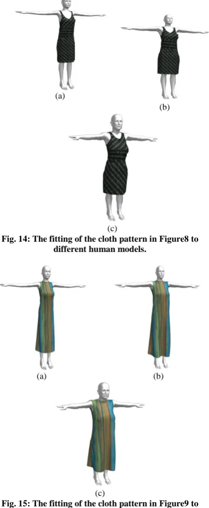
Figure 14 and Figure 15 show the fitting of the cloth pattern in Figures 8 and 9 respectively to different human models using the proposed panel resizing approach to fit all the panels. Then, the panels are sewn together to construct the 3D garments.
(a) (b)
Fig. 6: (a) The original scanned patterns. (b) The boundary of the panels extracted using the proposed
approach
.
(a) (b)
Fig. 7: (a) The original scanned patterns. (b) The boundary of the panels extracted using the proposed
approach.
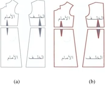
(a) (b)
Fig. 8: (a) The original scanned patterns. (b) The boundary of the panels extracted using the proposed
approach.
(a) (b)
Fig. 9: (a) the original scanned patterns. (b) The boundary of the panels extracted using the proposed approach.
(a) (b)
Fig. 10: (a) the original scanned patterns. (b) The boundary of the panels extracted using the proposed
[image:6.595.55.289.107.291.2] [image:6.595.60.233.486.627.2] [image:6.595.321.463.571.718.2](a) (b)
Fig. 11: (a) The original scanned patterns. (b) The boundary of the panels extracted using the proposed
approach.
(a) (b)
Fig.12: (a) The original scanned patterns. (b) Incorrect boundary of the panels extracted using the proposed
approach.
(a) (b)
Fig.13: (a) The original scanned patterns. (b) Incorrect boundary of the panels extracted using the proposed
approach.
6.
CONCLUSIONS
Classical patterns in old books and magazines are available only in hardcopy forms; to reproduce such patterns it is more convenient to obtain softcopies of those patterns. In this paper, a novel approach is introduced for fully automated extraction of panels from cloth pattern images and producing different size patterns from a given pattern size. A software package has been developed, and tested it on many cloth pattern images and different 3D models. The proposed approach accurately extracts the panels from cloth pattern images and perfectly fits them to different human models. Thus, the proposed approach is consequently very helpful for computer generated movies, computer games, and cloth design industry.
(a)
(b)
[image:7.595.58.271.71.167.2](c)
Fig. 14: The fitting of the cloth pattern in Figure8 to different human models.
(a) (b)
[image:7.595.327.539.79.593.2](c)
Fig. 15: The fitting of the cloth pattern in Figure9 to different human models.
7.
REFERENCES
[1] Charlie C. L. Wang.2004. CAD Tools in Fashion/Garment Design. Computer-Aided Design and Applications, Vol. 1, No.1, pp. 53-62.
[2] J. Vince and R. Earnshaw, Protopsaltou, D., et al. 2002. A Body and Garment Creation Method for an Internet-Based Virtual Fitting Room. Advances in Modeling, Animation and Rendering, Springer-Verlag, 105-122.
[image:7.595.340.541.79.325.2] [image:7.595.59.277.245.387.2] [image:7.595.58.271.454.577.2][4] Autodesk 3ds Max. http://usa.autodesk.com/3ds-max/.Last accessed on July 2014.
[5] AgnieszkaCichocka, Pascal Bruniaux.2009. Comparison of Traditional 2D and Virtual Patterns Design in 3D. Journal of Advanced Computational Intelligence and Intelligent Informatics, Vol.13, No.5 pp. 542-549.
[6] Li, J., Ye, J., Wang, Y., Bai, L. 2010. Fitting 3d garment models onto individual human models.Computers & Graphics, Vol. 34, No.6, pp. 742–755.
[7] Xu, C., and Prince, J. L. 1998. Snakes, shapes, and gradient vector flow. IEEE Transactions on Image Processing, VOL. 7,NO. 3, pp. 359 – 36.
[8] Saxena, Anupam, Sahay, Birendra. 2005. Computer Aided Engineering Design. Springer.
[9] O. Ismail.2010. Degree elevation of interval Bezier curves using Legendre-Bernstein basis transformations. International Journal of Video & Image Processing and Network Security (IJVIPNS), Vol. 10, No.6.
[10] Gonzalez Woods and Eddins.2009. Digital Image Processing Using Matlab.Gatesmark Publishing; 2nd edition.
[11] Jonathan M. Kaldor, Doug L. Jame.2010. Efficient Yarn-based Cloth with Adaptive Contact Linearization. ACM Trans. Graph,Vol. 29, No. 4, Article No. 105.
[12] Baraff , D., and Witkin, A. 1998. Large steps in cloth Simulation.Proceedings of the SIGGRAPH ‘98. pp.23-34, Orlando, FL, USA.
[13] Kwang-Jin,Hyeong-Seok. 2002. Stable but responsive cloth.SIGGRAPH’02, pp. 604-611, San Antonio, TX, USA.
[14] Carignan M, Yang Y.1992. Dressing animated synthetic actors with complex deformable clothes. In Proc. of SIGGRAPH’92. pp. 99–104, Chicago, Illinois, USA.
[15] Breen, D., House, D., and Wozny, M. 1994. Predicting the drape of woven cloth using interacting particles. In Proc. of SIGGRAPH’94, pp 365–372. Orlando, FL, USA.
[16] Eberhardt B, Weber A. 1996. A fast, flexible, particle-system model for cloth draping. Computer Graphics and Applications, IEEE, Vol. 16, No. 5, pp. 52 - 59.
[17] Pascal Vollino, Martin Courchesne. 1995. Versatile and efficient techniques for simulating cloth and other deformable objects. In Proc. of SIGGRAPH’95, Los Angeles, USA, pp.37–144.
[18] Jerry Wef.1986. The Synthesis of Cloth Objects. In Proc. of SIGGRAPH’86, Dallas, USA, Vol. 20, No.4.
[19] Eischen, J.W. 1996. Finite-Element Modeling and Control of Flexible Fabric Parts. Computer Graphics and Applications, IEEE, Vol. 16, No. 5, pp. 71 - 80.