LEADING AN ELECTRON BEAM IN A THREE-SECTION
LINEAR ACCELERATOR
Vladimir Kuzmich Shilov, Aleksander Nikolaevich Filatov and Aleksandr Evgenyevich Novozhilov
National Research Nuclear University MEPhI (Moscow Engineering Physics Institute) Kashirskoye Shosse, Moscow,Russian Federation E-Mail: [email protected]
ABSTRACT
The scale of human economic activity and the specificity of modern technological processes used in industry, especially in chemical industry and metallurgy, require special measures for environment protection. For practical purposes, linear electron accelerators operating in pulsed mode are currently used. Such accelerators may have sufficient beam power for efficient use in the industry and for environment protection. This paper shows the fundamental possibility of leading an electron beam by own high-frequency fields of accelerating resonators in linear accelerators with standing wave made on the basis of bi-periodical slow-wave structures. The results of numerical calculation of electrons dynamics with various initial conditions have been shown. The obtained results have been used to create a three-section accelerator, for which the calculated and experimental data have been shown. The performed experimental studies have confirmed the possibility of creating a standing wave linear accelerator without an external magnetic focusing system with the output beam diameter not exceeding5 𝑚𝑚. The results of beam dynamics calculations have been experimentally confirmed.
Keywords:linear electron accelerator, bi-periodical slow-wave structure, cell electromagnetic field, buncher, accelerating section, radial and phase trajectories.
INTRODUCTION
The progress in development of accelerating devices has provided the possibility of linear accelerators practical use in economic activity, which significantly increases efficiency of industrial production. Accelerating devices are more and more widely used in medicine [1]. Radiation therapy allows combining the relatively high efficiency of treatment and the possibility of mass treatment.
In the range of low to medium energy, traveling wave accelerators are used, but where a need for a compact accelerator arises, standing wave accelerators have a certain advantage. In paper [2], operation modes of linear electron accelerators (LEA) have been compared, and the expediency of creating small and medium energy standing wave accelerators has been shown.
Analysis of decelerating radiation output characteristics in radiography and radiation therapy [3] shows that most radiation tasks in these areas can be solved by using LEA of the energy equal to 4 − 6 𝑀𝑒𝑉 and the pulse current of50 − 150 𝑚A. Accelerators for non-destructive testing and medicine should have small longitudinal and transverse dimensions. Reducing the size and the weight of the radiation installations is an important and urgent task [4]. Reducing the longitudinal dimensions can be achieved by transition to the standing waves mode [5], while a bi-periodical slow-wave structure (BSWS)
with high shunt resistance [6] is used as the slow-wave system in the standing wave LEA.
Let us consider this issue in more detail in the Annex to the standing wave BSWS-based LEA accelerating systems, where the use of this effect seems to be very promising due to the high value of the radial component of the electric field, and the ease of technical implementation of focusing [7]. As soon as after the first 2-3 accelerating cells, the electrons gain the speed that is close to the speed of light, and then the optimum phase of entry into accelerating cells is selected, the electrons will be more affected by the focusing power, rather than the defocusing one.
The use of this effect makes it possible to abandon external focusing elements, reduce the dimensions of the accelerating system, reduce the weight of the installation, and, besides, eliminate the need for bulky power sources for the focusing system. This is especially important for mobile radiation units used in radiography, in malignant tumors radiation therapy, and for radiation borehole logging in geology.
METHODS
General provisions
Figure-1. Layout of the accelerating part of a three-section accelerator: 1 - injector, 2 - buncher, 3, 5 - focusing coils, 4 - first accelerating section, 6 - second accelerating section.
The accelerator consists of three separate sections - the buncher and two accelerating sections. Sections of the accelerator are made on the basis of (BSWS) with internal connection cells. The buncher consists of three variable geometry accelerating cells with 𝛽𝑝ℎ< 1and two connection cells. Accelerating sections are identical, and have 7 accelerating cells each, with 𝛽𝑝ℎ= 1, and 6 connection cells each. The buncher is powered from the main line via a directional coupler and a phase shifter, which can change the phase conditions between high frequency (HF) fields of the buncher, and the first accelerating section. The accelerating sections are powered through a three-decibel directional coupler, which determines the phase shift between the accelerating sections that is equal to 𝜋
2.
External focusing system is provided in the accelerator, consisting of three coils made of oxidized aluminum foil. The magnetic field in the first accelerating section is created by two coils, and reaches on the axis1,200 𝑂𝑒, and in the second accelerating section - by one coil with the magnetic field intensity on the axis of800 𝑂𝑒.
At the entrance into the buncher, the electronic injector creates a beam with the diameter of0.15 𝑐𝑚, spread of1○, current of up to 300 𝑚𝐴 and energy of40 𝑘𝑒𝑉.
The calculations of particles dynamics in such standing wave accelerators based on BSWS [9] allowed identifying the main parameters of the slow-wave system, which mainly determine the behavior of the particles in the accelerator. These parameters include: radius and divergence of the injected beam, intensity of the external focusing magnetic field, intensity of the accelerating electric field, geometry of the accelerating and bunching cells, phase relationship between the buncher and the first accelerating section. Since some of them have been
pre-defined (characteristics of the beam – by the electron gun, intensity of the accelerating field - by the characteristics of BSWS), it only remains to determine the effect of the bunching cells geometry, intensity of the accelerating field in these cells, phase shift of HF fields in the buncher, and the first accelerating section and intensity of the external magnetic field on beam dynamics.
Dynamics of particles
Particle dynamics will be calculated with hydrodynamic approximation, considering the flow of particles to be laminar. This approach results in a considerable gain in the time of count, since there is no need to monitor movement of the internal particles in the beam; it is enough to consider the motion of a particle in the initial radius, which is equal to the radius of the injected beam.
Beam dynamics is to be considered separately in the buncher and in the accelerating sections. This is due to the fact that the beam has to enter the accelerating section, being already formed in terms of phases and the radius, and its guidance will depend on the phase of bunches entering the first accelerating section. The main processes of beam formation should finish at the exit from the buncher, so calculation of particle dynamics should be made most carefully.
Let us separately consider the buncher, which is discussed in detail in [10]. Based on this method, a buncher with the following parameters is calculated and adjusted: 𝛽𝑝ℎ1= 0.42, 𝛽𝑝ℎ2= 0.67, 𝛽𝑝ℎ3= 0.92, the maximum electric field intensities in the centers of accelerating gaps are 37, 200, 200 𝑘𝑉/𝑐𝑚, respectively.
Figure-2. (a) - radial trajectories of particles in the buncher for various initial phases: 1 − φ0= 0.2π, 2 − φ0= 0.6π, 3 − φ0= π, 4 − φ0= 1.4π; (b) are phase
trajectories of the particles in the buncher.
One can see that the buncher holds up to 50% of injected particles in the area of the aperture, whereby their phase regrouping occurs from 180○ to 40○ at the exit from the buncher. Up to 20% of injected particles (𝜑0= 0.4 𝜋, 𝜑0= 0.6 𝜋, 𝜑0= 1.4 𝜋) are in favorable conditions for radial movement, and their trajectories are significantly closer to the axis. By phases, these particles are grouped into almost a point bunch, and gain kinetic energy up to 700 𝑘𝑒𝑉, so it may be assumed that it will be possible to guide this part of injected particles through the accelerating sections without the use of the external focusing field.
Since the geometry of the cells in the accelerating sections is determined from the assumption of the maximum effective shunting resistance, and is known in
advance, while the electric field intensity in these cells is determined by the power of the generator, and in all cells for the nominal mode is equal to 120 𝑘𝑉/𝑐𝑚, further particles dynamics in the accelerator is determined by the phasing of the first accelerating section, relative to the buncher.
Using the phase shifter, one can phase the accelerating section so that most accelerated particles pass through the accelerator. It does not seem feasible to guide all particles through an accelerator, due to the finite (about40○) phase spread of the bunch. On the other hand, the optimum mode of particle acceleration, i.e. the maximum energy gain, is not implemented in this case. These known contradictions require a compromise solution [11]. All the above is illustrated in Figure-3.
Figure-3(a) shows the curves of the maximum deviation of the particle trajectories from the accelerator axis for various initial phases, depending on the wave phase shift in the accelerating section relative to the buncher ∆𝜑. Figure-3(b) shows the dependencies of particles energy on parameter ∆𝜑. Analyzing the obtained results, we can determine the intervals of wave phase shift change in the accelerating section, relative to the buncher, which are optimal for accelerating particles and their radial movement. With values ∆𝜑 = (0.64 ÷ 0.8)𝜋, particles gain the maximum energy, but the conditions for radial movement are such that most energetic particles still remain on the walls of the passing channel. However, even in these conditions, about 20% of the injected particles pass through the aperture of the accelerator.
In case of phase shift ∆𝜑 > 0.8 𝜋, the radial characteristics of the beam improve significantly, however, the energy gain is dramatically reduced. Apparently, the compromise will be phase shift ∆𝜑 = 0.8 𝜋 in the wave accelerating section, related to the
buncher, when the conditions for energy gain and for radial motion of particles may be considered satisfactory.
DISCUSSION AND RESULTS
Thus, calculation of particles dynamics throughout the entire accelerator confirms the assumption that without a significant loss in the energy gain, about 20% of the injected particles may be guided through the accelerator without any external magnetic focusing devices.
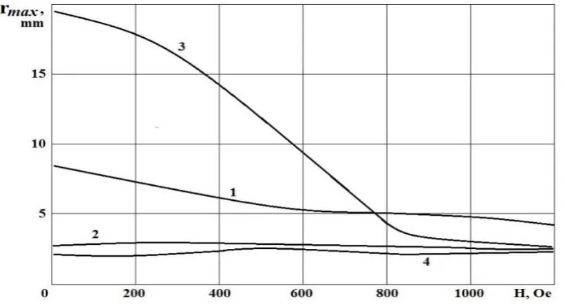
[image:4.595.92.503.356.577.2]The radial and energy characteristics of the beam may be improved with the use of focusing coils, which can create magnetic fields with intensity along the axis of the accelerator of up to 1,200 𝑂𝑒. To assess the effect of the external magnetic field on the radial characteristics of the beam, a series of calculations of the particles radial dynamics in case of changing the external magnetic field from 0 to 1,200 𝑂𝑒 was made. The results are shown in Figure 4 in the form of dependencies of the maximum particles trajectory deviation from the axis for various initial phases on the magnetic field intensity.
Figure-4. Dependency of the particles trajectories maximum deviations on the intensity the external magnetic field. The parameter is the initial phase: 1 − φ0= 0.2π, 2 − φ0= 0.6π, 3 − φ0= π, 4 − φ0= 1.4π.
Figure-4 shows that the external magnetic field significantly improves the radial movement of the particles. Fields with intensity of 800 𝑂𝑒 and higher guide 50% of the injected particles through the aperture of the accelerator; even the high-energy particles that previously fell onto the walls of the pass channel due to the radial movement now reach the end of the accelerator.
Thus, the calculation of particle dynamics in the accelerator yielded the following results:
- there is a real possibility of guiding up to 20% of the injected particles through the accelerator without the use of external focusing elements; in
this case, the average energy of the beam is 4.5 𝑀𝑒𝑉;
- with the initial diameter of the injected beam equal to 1.5 𝑚𝑚, and the initial spread of 1○, the beam diameter at the exit of the accelerator does not exceed 5 𝑚𝑚;
- the use of external focusing devices with intensity of the magnetic field along the axis of 800 𝑂𝑒 increases the current in the beam at the exit from the accelerator 2 ÷ 2.5times with beam diameter at the exit from the accelerator not exceeding 3 𝑚𝑚;
- the range of phase shift of HF fields between the buncher and the first accelerating section, whereby the maximum energy gain by the particles occurs, t ∆𝜑 = (0.64 ÷ 0.8)𝜋.
As a result of experimental research of accelerator operation, the average kinetic energy of electrons, the pulse current, the beam size at the exit from the accelerator, and the phase length of bunches were measured, and the experimentally obtained characteristics of the beam were compared to the calculated ones.
Figure-5. Experimental dependency of the average beam energy on phase shift of the HF field of the buncher, relative to HF field of the first accelerating section (a) and dependency of the pulse current at the exit from the accelerator
on the current in the focusing coils (b).
Figure-5(a) shows the experimentally obtained dependency of the average beam energy on the buncher field HF phase shift depending on the HF field of the first accelerating section. This figure shows that the range of phase shift variation that results in the maximum energy gain by the particles is equal to 20○, and the calculated value is 30○.
CONCLUSIONS
The experimentally measured length of the accelerated bunches was (51 ± 5)○, and, according to calculations, this value should not be less than 40○.
Figure-5(b) shows the experimentally obtained dependency of beam current on the current of the focusing coils. The maximum beam current of 115 𝑚𝐴 was reached with the current in the focusing coils of 16 𝐴 that corresponded to the intensity of the magnetic field of 550 𝑂𝑒, the capture rate in this case is equal to 30%. The corresponding calculated values are 800 𝑂𝑒 and 50%. In the absence of the focusing magnetic field, the capture rate falls to 20%. The calculated value of the capture rate is also equal to 20%.
The prints of an accelerated electron beam obtained in the existing accelerator show that the main part of the beam in the absence of the focusing magnetic field is concentrated in a circle with the diameter of 5 𝑚𝑚, and with the external magnetic field - in a circle with the diameter of 2.5 𝑚𝑚. The corresponding calculated values are equal to 5 𝑚𝑚 and 3 𝑚𝑚.
The performed experimental studies have
be considered that the results of beam dynamics calculations in a three-section accelerator have been experimentally confirmed.
ACKNOWLEDGEMENTS
This work was supported by MEPhI Academic Excellence Project (contract No. 02.a03.21.0005, 27.08.2013).
REFERENCES
[1] Zhang M., Li S., Deng H. & Zhou S. 2013. Technical Note: The Uses of I’mRT MatriXX in Electron Beams. International Journal of Medical Physics, Clinical Engineering and Radiation Oncology. 2(1): 15-18.
[2] Zаvаdtsеv A. 1994. Biperiodic U-structures for
Particle Accelerators. Fourth European Accelerator Conference. (Vol.3), London. pp. 2176-2178.
[3] Belovintzev K., Bukin A. and Gaskevich E., et al. 1994. Radiation complex for fundamental and applied research. 14th conference on charged particles' accelerators, Protivino. 4, 264-268.
linac. Nuclear Instruments and Methods in Physics Research A.795, 343-350.
[5] Knapp E. A., Knapp B. C. and Potter J. M. 1968. Standing Wave High Energy Linear Accelerator Structures, Rev. Sci. Instrum.39, 979.
[6] Vikulov F., Zverev B. and Zavadtzev A., et al. 1980. Small-sized linear electron accelerator with standing waveand bridge power circuit. Accelerators, 19. Moscow: Atomizdat.
[7] Novozhilov A.E. et al. 2016. Calculation of Resonant Frequencies and Electromagnetic Fields in Resonators of Linear Accelerators for Commercial Application, Medicine and Environmental Protection. Research Journal of Pharmaceutical, Biological and Chemical Sciences. 7(2): 897-905.
[8] Novozhilov A.E., et al. 2014.Assessment of method errors in measurement of acceleration fields in accelerating sections of charged particle accelerators. Life Science Journal.11(11s): 506-510.
[9] Filatov A.N. & Shilov V.K. 1984. RF Focusing in the Standing-Wave Electron Linacs. Soviet physics. Technical physics. 29(2): 163-167.
[10]Novozhilov A.E., et al. 2017. Calculation of bunchers in linear electron accelerators with standing wave. ARPN Journal of Engineering and Applied Sciences. 12(1): 182-187.