OPTIMIZING THE SYSTEM PERFORMANCE OF POI-1000M FOR
ACCEPTANCE TEST PROCEDURE
Nor Hafizah Abdullah, Asmaliza Zulkifli, Karthigesu Thanarasi and Maszlan Ismail
Operational and Space Systems Division, National Space Agency, Banting, Selangor, Malaysia E-Mail: [email protected]
ABSTRACT
This paper outlines the requirement for a successful measurement of an equipment named Mass Properties Measurement System (MPMS) which capable to calculate the center of gravity (CG), moment of inertia (MOI) and Product of Inertia (POI) of a satellite. POI-1000M is the model type for this equipment which can measure a specimen from 10 kilogram and up to 1 ton in weight. Go through a factory acceptance test (FAT) is compulsory before receiving a machine, which has been done earlier in Connecticut, USA. Then, National Space Agency (ANGKASA) which acts as a Malaysian Government Agency has to experience through an Acceptance Test Procedure (ATP) to compare on the performance review with FAT. This ATP was conducted on determining the requirements of a specification or contract are met or not by conducting test which is commonly applied for engineering and its various subdisciplines. The ATP was done in ANGKASA headquarters located in Banting, Selangor and have been witnessed by a Malaysian Research Institute; SIRIM Berhad, local and international contractors as well as the principal of the equipment itself. The ATP may involve chemical tests, physical tests, or performance tests by comparing the results with FAT. Both environmental condition and steady equipment preparations gave big influence for having optimum reading. POI-1000M Rotary table, deadweights and a compressor are the main components assisted by a control system used by operators to calculate the desired measurements during the ATP. By comparing both the ATP and FAT results, it has been confirmed that the equipment is successfully approved and satisfied on its performance
Keywords: mass properties measurement system, POI-1000M, optimizing system performance, acceptance test procedure.
INTRODUCTION
During satellite integration and assembly process, there are few tests need to be conducted by each satellite which called environmental test. Because of satellites cannot be tested in flight, the tests have to take place by simulating the extreme conditions of the launch and orbital environment as realistically as possible (Space-airbusds, 2011). For this test, the laboratory or clean room has been designed specifically to duplicate the space environment under one building named Assembly, Integration and Test (AIT) facility which situated in ANGKASA, Banting, Selangor. AIT consists of 6 different tests where Mass Properties Measurement is one of the environmental tests need to be experienced by each satellite owner. Apart from that, others such as electromagnetic chamber test, vibration test, thermal test, acoustic test and alignment measurement are the required test for a spacecraft before the launch campaign. Furthermore, the tests are used to ensure that the end product which the spacecraft and its components can achieve all the design, performance and quality requirements are at the satisfied condition.
The development phase of a satellite tests such as qualification testing, acceptance testing and pre- launch validation testing must be coordinated well with other testing programs to verify and qualify a satellite towards the successful launch campaign. For a satellite in an orbit, solar panels and antenna have to point towards sun and earth respectively in order to having continuous communication, even if the spacecraft is rotating the earth (Gowda et al., 2012). Hence, in maneuvering the
spacecraft in the orbit, exact torque has to be calculated and controlled using actuators which depend upon CG and MOI of spacecraft in deployed condition. This crucial step
for developing a satellite is needed to confirm the specified tolerances are within the agreed values. Otherwise, some minor corrections should be done by adding some ballast to avoid significant deviations during component manufacturing or satellite integration (Wiener, 2005). In this paper, the necessity of having an acceptance test of POI-1000M is to demonstrate the technical performance of the equipment is in acceptable limits by using the test standards that are traceable to the National Institute of Standards and Technology (NIST) (Space Electronics, 2007a).
METHODOLOGY
Calibration
2007b). Then, a result of calibration will be displayed in chart which gives the correction values to correct raw data for both amplitude and angle.
[image:2.612.314.540.101.168.2]
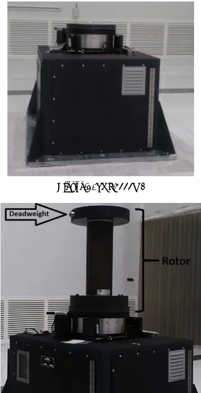
Figure-1. POI-1000M.
Figure-2. Calibration setup; using rotor.
Figure-1 above shows the main machine, POI-1000M. It has to be calibrated before measuring the desired CG, MOI or POI. Both pictures of Figures 1 and 2 have been taken during on-site acceptance and installation process in ANGKASA, Banting. As shown in Figure 2, the proving rotor has been mounted onto the POI-1000M and is used to place the deadweights for balancing purpose in calibration procedure. What makes the difference between factory acceptance and on-site acceptance test is by having different location which the FAT was done in factory place (USA) while the ATP was conducted at the owner laboratory (ANGKASA). The test should be in similar condition for both places by having an optimum location condition which is inside the clean room with
Table-1. Calibration result.
Centre of gravity calibration
Calibration Passed/Fail Passed
Calibration Constant 0.1359435 Calibration Angle 359.9890
Table 1 shows the calibration result where the computer compares the calibration constant with the nominal value stored on the disk. In case the difference value happen to be more than 2% variation, the new value is discarded and the previous value is retained (Space Electronics, 2007c). The message of ‘passed or failed’ displayed by the computer is to accommodate the operator in eliminating any errors during calibration process. Calibration beam and deadweight will be used for this step by following the operating manual. The most current calibration constant will always be used for calculations as the principal; Space Electronics LLC recommends that the calibration procedure be repeated at 6 months intervals unless accuracy checks indicate that more frequent calibration is required (Space Electronics, 2007d).
Tare and part measurement
By following the procedure stated in manual instructions, tare measurement is the preliminary step to be executed after storing a valid CG calibration constant. Next, the part measurement will take place by complying all the commands given in the operating manual.
[image:2.612.83.287.131.529.2][image:2.612.326.532.424.559.2] [image:2.612.325.529.583.712.2]
Figures 3 and 4 show the example of tare and part measurements; operation procedures to be followed before conducting the calculation step for CG measurement. Some data have to be inserted for an instance the weight value of deadweight, required radius measurement and the height for different weight located at the different point of beam. Some values can be referred from the certificates given by the manufacturer or required calculations depend on the desired parameters.
Calculations
Finally, when all necessary measurements for a test part have been taken, the operator may continue with the CG calculations to complete the process of ATP procedure. All data will be stored in the database and operator may print out the result directly after receiving the measurements results.
Figure-5. CG Calculation command.
Figure-6. Calculation result.
RESULTS AND DISCUSSIONS
ATP and FAT
The MPMS comprises of a balancing system mainframe of POI-1000M, a remote control console, a computer (data acquisition system - DAQ) and an air compressor that provides clean dry air or nitrogen (7 bars @ 56.64 liters per minute) for the air bearing system of POI-1000M (RazakSAT Structural Model, 2013). This instrument is configured to have maximum sensitivity when measuring objects weighing 10 to 1000kg. The DAQ acts as a brain to this system and control the operation service. A spherical gas bearing used in this instrument is virtually frictionless. It has bearing noise and run-out which is so small that cannot be measured using conventional means (Space Electronics, 2007e).
On 26th February 2013, ANGKASA has carried out the ATP in Mass Properties Measurement laboratory at AIT facility of National Space Centre, Banting. It is a clean room that is classified as ISO 8, in accordance to ISO 14644-1 standard with temperature controlled at 23±2oC and relative humidity at 50±5%. During the measurement, any heavy physical activities that induce vibration are strictly prohibited. The ATP result is to be compared with the FAT where it had been tested on 28th September 2007.
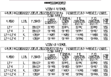
Table-2. ATP result.
Center of Gravity Data Maximum allowable error: ε = (0.1% of actual moment + 0.58kg-mm) / actual mass + 0.05mm
Weight Hole Mass (kg) radius (Actual mm) Measured radius
(mm)
Min acceptable
(mm) (1)
Max acceptable
(mm) (2)
Pass/ Fail
CG-1 C 8.41663 761.97 762.04 760.46 763.47 Pass CG-2 A 8.41663 1511.35 1511.97 1509.10 1513.60 Pass CG-1, CG-2 B 16.8330 1142.99 1142.83 1141.45 1144.52 Pass CG-1, CG-2 G 16.8330 1511.33 1511.33 1509.42 1513.24 Pass
Table-3. FAT result.
Center of Gravity Data Maximum allowable error: ε = (0.1% of actual moment + 0.58kg-mm) / actual mass + 0.05mm
Weight Hole Mass (kg) radius (Actual mm)
Measured radius
(mm)
Min acceptable
(mm) (1)
Max acceptable
(mm) (2)
Pass/ Fail
CG-1 C 8.41663 761.97 763.08 760.46 763.47 Pass CG-2 A 8.41663 1511.35 1512.77 1509.10 1513.60 Pass CG-1, CG-2 B 16.8330 1142.99 1143.63 1141.45 1144.52 Pass CG-1, CG-2 G 16.8330 1511.33 1511.39 1509.42 1513.24 Pass
Discussion on result performance
Table 2 and 3 give results for both ATP and FAT. As shown above, both stated positive result by their ‘pass’ status. This proves that the measurement values are within the accepted and valid results as the machine is conducted on a stable condition throughout the test. For POI-1000M measurement, basically when the pre-requisite calculation for both calibration and calculation give a good signal on their measurement, it may contribute to the machine to have less error on the test results. That’s why the installation process and environment factor should be well prepared to minimize the offset which may affect the result.
Good preparation is prime importance in getting good result. For optimization of performance result, every single step in operating the test would be consider as crucial procedure to be followed due to reducing any possible mistake that could happen. Environmental considerations such as temperature change should be noted earlier to keep stable temperature throughout the test. Temperature change may affect the properties of the part itself where the increment on temperature may give unstable readings and causing unbalance due to sudden changes in temperature. This machine is quite sensitive to the moist condition which may affect the reading to be less accurate.
In addition, a strategic location is one of the main significance factors where the test operator should aware not to locate the balance machine near compressors, vacuum pump or punch presses that may have a
Machine to be isolated from surrounding floor vibrations. During test performance, any vibration activities should be stopped. This is because every measurement of calibration, tare and part are depending on the consistency environment temperature otherwise there will be a measurable errors introduced. Once this factor cause errors in the calibration, the subsequent measurement for tare and part measurement will contribute the error too. Anyhow, the spin balance machine should be maintained annually to optimize and maintain the performance and its stability as well as to prevent any damage which may occur.
Preventive maintenance do play an important role in order to reduce equipment failures that could occur during testing. For MPMS, preventive maintenance is performed regularly which is 4 times per year. Checking on the electronic wiring, spin balance machine’s control system, crane system functionality and calibration validity are the main item need to be monitored and listed in the schedule. As a result, implementing preventive maintenance helps to establish consistent practices designed to improve the performance and safety of the equipment in the laboratory.
CONCLUSIONS
System (MPMS) which headed by the Director of Operational and Space System Division of ANGKASA (BPOA), Mr. Maszlan bin Ismail for their guidance and help in this research. Thousands of gratitude are also given to the Assembly, Integration and Test (AIT) team for their encouragements and contributions in the process of completing all the project requirements as well as the assistance and support in acquiring the data analysis.
REFERENCES
Satellite assembly, integration and test retrieved August 24, 2011 from http://www.space- airbusds.com/en/news2/satellite-assembly-integration-and-tests-kqn.html.
R. Gowda, P. Mathur, P. Swapnil, Ravi T., C.K.Rao, N.S. Sundaram, G. V. C. Rajan, Govinda K.V. 2012. “Techniques for Measurement of Centre of Gravity & Moment of Inertia and their Importance in Spacecraft Attitude Control”, Systems Integration Group, ISRO Satellite Centre, Bangalore.
K.H. Wiener, The Role of Mass Properties Measurement in the Space Mission, European Conference on Spacecraft Structures, Materials & Mechanical Testing. 2005. Noordwijk, the Netherlands, 10 – 12 May 2005 (ESA SP-581, August 2005).
Space Electronics (2007a), Standard 0138B Acceptance Test Procedure for Model POI-1000M, p. 58.
Center of Gravity retrieved May, 2015 from https://www.grc.nasa.gov/www/k-12/airplane/cg.html.
Center of Mass retrieved November, 2015 from https://en.wikipedia.org/wiki/Center_of_mass#Center_of_ gravity
Space Electronics. 2007b. Model POI-1000M Operating Instructions. pp. 15-16.
Space Electronics. 2007c. Standard 0138B Acceptance Test Procedure for Model POI-1000M, p.7.
Space Electronics, (2007d), Standard 0138B Acceptance Test Procedure for Model POI-1000M, pp.17.
RazakSAT Structural Model (SM). 2013. Test Jig Mass Properties Measurement Procedures, 2013, p. 8.