Over The Air Updates of SIM card using GSM modem
Deepak Kumar
**
Research and Development, Syscom Corporation Limited(A Morpho Company)
Abstract- Over the air (OTA) is a platform by which GSM provider can send and receive services from and to SIM card. Such OTA Platform are expensive and implemented on operator side only. If SIM vendor want to perform online testing of SIM services they need an special online account with Operator to access their OTA service. To overcome this limitation, GSM modem can be used to perform online testing without special access of operator OTA server with support of “exposesd” API of GSM modem.
Index Terms- OTA, SIM, GSM, Modem, USB, Serial,AT,PDU
I. INTRODUCTION
O
ver the air (or Over-The-Air) is a technology / standard for the transmission and reception of application-related information in a wireless communications system. Using OTA, services provider can perform various new software updates, configuration settings, and even update of encryption keys to devices like mobile phones, DTH set top box or voice communication device. Over the air technology also enables an operator to introduce new SIM services and to modify Over the Air content of SIM cards in a rapid and cost effective way. OTA is based on client/server architecture where at one end there is an operator’s back-end system (like support system, auto bill system & could be application server also ) and at the other end there is a SIM card.The operator's back-end system sends service requests to an OTA Gateway which transforms the requests into Short Messages and sends them onto a Short Message Service Centre (SMSC) which transmits them to one or several SIM cards in the field. This paper focus on propose solution for SIM update via OTA using GSM modem only.
In General if OTA technology need to implement, the following components are must needed:
A back end system to send requests.
A Over the air gateway to process the requests in an understandable format to the SIM card.
A short message service center to send requests through the wireless network.
A medium to send the request: today it is the SMS bearer.
Mobile device to get the request and transmit it to the SIM card.
A working SIM card to receive and execute the request.
These above system comprise a complete package which help SIM vendor to perform their online testing but with an expensive
subscription, complex procedure & most important always have dependency on network operator to get access. Now further we are discussing what is actually a “GSM modem” is and how we could replace it with such an huge & complex OTA system which is implemented at server side.
G
SM modem is a specialized hardware with a serial or USB connectivity, which accepts a standard size SIM card & operates over a subscription to a mobile operator, it is similar like a mobile phone. When any GSM modem is connected to a PC, It allows the computer to use the GSM modem to communicate over the mobile network. A GSM modem exposes some “interface” that allows PC’s applications to send and receive messages over the modem interface. Using this provided interface of Modem, User can perform Over the AIR (OTA) testing of SIM card using different GSM Sms services.For the purpose of this paper, the phrase GSM modem is used as a generic term to refer to any modem that supports one or more of the protocols in the GSM evolutionary class, It include the 2.5G, GPRS and EDGE technologies, as well as the 3G technologies WCDMA, UMTS, HSDPA and HSUPA also. GSM modems is a quick & efficient way to get started with Short message service (SMS), because a special subscription with an SMS service provider is not required & sender itself is paying for the message delivery.
A GSM modem could be a dedicated device with a serial, USB connectivity or Bluetooth connection, such as the Falcom Samba 75, Centrion MC35i, Wavecom, Multitech and iTegno.
A GSM modem could also be a standard GSM mobile phone with the appropriate cable and software driver to connect to a serial port or USB port on your computer. Additionally any phone that supports the “extended AT command set” for sending/receiving SMS messages can also be used as GSM modem.
GSM
modem Frequency(MHz) Modem type
Ultralight 900/180 EDGE
Cinterion 900/1800 GSM/GPRS/EDGE
Samba 75 850/900/1800/1900 GSM/GPRS/EDGE
iTengo 850/900/1800/1900 GSM/GPRS
Multitech 850/900/1800/1900 GSM/GPRS/EDGE/HSPA +
Wavecom 900/1800 GSM
Research Elaboration for proposed solution- Basic thought behind this paper is to provide an approach and solution to replace such a huge system of expensive subscription & server dependency where SIM vendor itself can not perform OTA updates / Service on SIM card they are supplying until they have access to some operator specific premium service which are quite expensive & always have dependency on operator to do such OTA updates on SIM. Such dependency could be remove with special hardware device know as GSM modem.
For this purpose, a GSM modem, application interface & dedicated Server (optional but good to have) required which can access to exposed interface of GSM modem. This application interface allow user to send / received any kind of SMS from & to SIM card. The kind of message send and receive via GSM modem could be GSM /3GPP compliance text message , Cell broadcast message & SMS PP Data download message.
II. PROPOSED IMPLEMENTATION
The Personal Computer (PC) provides a user interface to the GSM modem(this could be silent java api or user interface), Where GSM modem is operated in special mode called Protocol Data Unit (PDU) mode, which allows SIM vendor to message with required content as per their requirement (i.e. message could be of text or data download or broadcast message). All short message service (SMS) are transmitted with special OTA commands for the SIM card (here card could be Java or Native but must compliance to GSM03.48 & GSM03.40). These are special commands (APDU) for the cards which is understood by Network, mobile equipment & SIM card. With this paper concept, SMS to be sent must be generated by PC application which could be divided into two parts:
The SMS header
The SMS-body
These two part required later in message sending process to include in AT command, which suppose to transmitted to the GSM modem by PC Application. AT command are special “AtTention” command which help PC Application to communicate with GSM modem.
Here GSM modem must contain a "normal" SIM with access to GSM network so that it can connected to SMSC. Once Modem connected to network it can receives the APDU generated by PC & using AT command generated APDU will be send to the selected SMSC. The SMSC forwards the SMS to the receiver with the help of destination address which PC application will include SMS header part.
The receiver is in this case actually have the test SIM (or any live SIM which required new service update) with any terminal (Mobile or M2M). Optionally, with SIM card monitor the communication between the SIM and the terminal can be logged, then it is possible to recognize how the SMS received by the terminal & it is forwarded to the SIM.
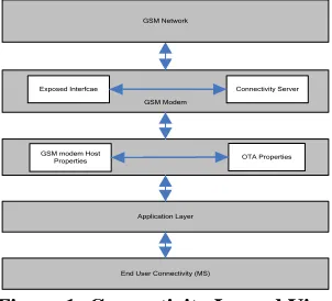
Application Layer GSM modem Host
Properties OTA Properties GSM Modem
End User Connectivity (MS)
Exposed Interfcae Connectivity Server GSM Network
Figure 1: Connectivity Layerd View
To implement such in house OTA system, complete communication is dived into following four steps & further we are discussing what are these steps and how it will implemented to get such system. As a outcome of these steps we will have a system where SIM vendor can send/receive an SMS from GSM modem to test or update services to SIM card’s:
1.PC GSM-Modem
2.GSM Modem SMSC
3.SMSC Terminal
4.Terminal Test SIM
With these steps whatever data need to transmit offline (To GSM modem) must be transmited via AT command & should transferred either via RS232 or RFID, depending on used GSM modem.
Further explaining how four step work. 1. PC GSM-Modem
There are two ways of sending and receiving SMS messages, by text mode and by PDU (protocol description unit) mode. To send any message in PDU mode(see Table5), The AT command "AT + CMGS" will sent from the PC to the GSM modem. The command data here can be transferred either via RS232 or RFID , depending on used GSM modem. Following are the AT command(See GSM07.07) need to implement in PC application.
1) AT Test Command Command
AT
[image:2.612.369.520.59.196.2]Response OK Table 2
2) AT+CPIN service Center Address (to entering SIM PIN)
Command AT+CPIN=?
Response OK Read Command
AT+CPIN=?
+CPIN:<code> OK
Write Command
AT+CPIN=<pin>[new pin] OK
[image:2.612.311.560.520.738.2]SCA : SC address coded according GSM04.11 ToSCA : Type of Address Table 3
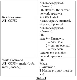
3) AT+COPS to gather information about available network
Command Response
AT+COPS=? +COPS:List of
<mode>, supported <format>]
OK (Returns the current network operator) Read Command
AT+COPS?
+COPS:List of
<stat>,<oper>, nummeric <oper>[,supported <mode>, supported <format>] OK
state 0 = Unknown, 1 = Available 2 = current operator 3 = forbidden Returns the available network operators Write Command
AT+COPS=<mode>[,<for mat>[,<oper>]]
OK, Mode: 0 Automatic,
1 Manual (<oper> must be set)
Table 4
4) AT+CSCA service center address: Specifying the service center to be used if this is not specified in the explicit SMS PDU .
Testcommand AT+CSCA=?
Response OK Read Command
AT+CSCA?
Response
+CSCA:<sca>,<tosca> OK
Write Command
AT+CSCA=<sca>[,<tosca>]
Response OK
[image:3.612.34.284.55.314.2]SCA : SC address coded according GSM04.11 ToSCA : Type of Address Table 5
5) AT+CMGF select message format : Switch between text
and PDU mode
Testcommand AT+CMGF=?
Response
+CMGF: (list of supported modes)
OK Read Command
AT+CMGF?
Response +CMGF:<mode> OK
Write Command
AT+CMGF=[<mode>]
Response OK
[image:3.612.311.561.57.157.2]Mode 0 PDU mode Mode 1 Text mode Table 6
6) AT+CMGS Send SMS direct from Terminal: Sending an SMS ( only PDU format )
Testcommand AT+CMGS=?
Response OK Execute Command
AT+CMGS=<length> <CR>
Response
PDU <ctrl Z>
Note: < lenght > indicates the longer the PDU passed , however, the bytes are not counted for the SMSC number .
+CMGS: <mr>[,ackpdu] OK
MR = Message Reference number
Table 7
After AT command Procedure, Now comes to the Structure of SMS Submit PDU:
The Data to be transferred to the GSM modem to send via a short message ( SMS Submit PDU ) consists of two main parts :
The address to be used SMSC ( optional)
The actual SMS -SUBMIT PDU , how it is transmitted in the network
It is composed as follows :
SCA FO MR DA PID DCS UDL DU
1-12 1 1 2-12 1 1 1 0-140
SCA Service Center Address
FO First Octet of submitted SMS (PDU-Type) MR Message Reference Number
DA Destination Address PID Protocol Identifier DCS Date Coding-Scheme
UDL User-Data-Length (Lengthof Characters) UD User-Data
For SMS Submit PDU seperate fields are explained below. A) Service Center Address ( SCA ): This field consists of three parts
Length of SCA
Type of SCA
Address Field B) First Octet ( FO ): 7 6 5 4 3 2 1 0 0 0 1 0 0 1 0 1
TP-MTI Message Type Indication: 01 'SMS-SUBMIT 00 'SMS-DELIVER TP-RD Reject Duplicates
0: No 1: Yes
TP-VPF Validity Period 0: No
1: Yes
TP-SRR Status Report Request 0: No
1: Yes
TP-UDHI User Data Header Ind 0: NoUDH
C) Message Reference Number (MR): Local reference number used for the mailing to instant message . Delivery reports or error messages may include this reference number. The modem may automatically assign a unique reference number, if MR is already given modem can use it.
D) Destination Address (DA): Recipient address, encoded as Service Center Address.
E) Protocol Identifier(PID):The SMs Protocol on which sending data is based,allowed scheme for modem are:
0x00 provides loud GSM 3:40 is the default value for text messages.
0x7F shows "SIM Data Download" F) Data Coding Scheme(DCS):
Indicates to the receiving terminal, such as the data of the short message to be decoded.
0x00 Class 0 Text message (7 bit character encoding)
0xF4 Class 0 Text message (8 bit character encoding)
0xF6 Class 2 message (SIM specific message, 8-bit coding)
G) User Data Length(UDL):Length of user data (User Data) H) User Data(UD):The actual user data,
2. GSM Modem SMSC
The GSM modem now transmits the received SMS to the selected SMSC . The SMSC away some fields of the PDU that are only relevant for the SMSC - Other information that has only the SMSC and are important for the recipients of the message are also included in the PDU so that the SIM card can understand the PDU. The actual user data are transparent, i.e. without any modification by the SMSC during transfer of data.
3. SMSC Terminal
When Modem has transmit the data to SMSC, SMSC has responsibility to transfer it to receiver end with the following structure (according to GSM 03.40).
SCA FO OA PID DCS SCTS UDL UD
1-12 1 2-12 1 1 7 1 0-140
SCA Service Center Address
FO First Octet of delivered SMS (PDU-Type) OA Orginator Address
PID Protocol Identifier
DCS Date Coding-Scheme
SCTS Service Center Time Stamp
UDL User-Data-Lenght (Length of Characters)
UD User-Data
The highlighted - printed fields of Deliver PDU were virtually one on one of the submit PDU adopted by the SMSC . The other fields were supplemented or modified .
Service Center Address ( SCA ): Address of the service center , which the SMS has passed . Encoding as mentioned above
First Octet ( FO ): This parameters are coded as follow. 7 6 5 4 3 2 1
0 0 0 1 0 0 1 0 1
TP-MTI Message Type Indication: 01 'SMS-SUBMIT 00 'SMS-DELIVER TP-MMS More Message to Send
0: No 1: Yes -
-
TP-SRR Status Report Request 0: No
1: Yes
TP-UDHI
User Data Header Ind 0: No UDH
TP-RP Reply Path 0: No 1: Yes
Originating Address (OA): Address of the sender of the SMS. Coding as above .
Protocol Identifier(PID):Protocol which is the sent data based. Data Coding Scheme(DCS):
Shows how the data of the short message to be decoded by the receiver .
Service Center TimeStamp (SCTS):Unique time stamp of when the ( incoming ) SMS has reached the service center .
User Data Length(UDL):Length of user data (User Data) User Data(UD):The actual user data,
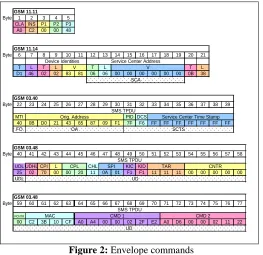
4. Terminal SIM
GSM 11.11
Byte 1 2 3 4 5
CLA INS P1 P2 P3
A0 C2 00 00 48
GSM 11.14
Byte 6 7 8 9 10 11 12 13 14 15 16 17 18 19 20 21
T L T L T L T L
D1 46 02 02 83 81 06 06 00 00 00 00 00 00 0B 38
GSM 03.40
Byte 22 23 24 25 26 27 28 29 30 31 32 33 34 35 36 37 38 39
MTI PID DCS
40 0B D0 21 43 65 87 09 F1 7F F6 FF FF FF FF FF FF FF
FO
GSM 03.48
Byte 40 41 42 43 44 45 46 47 48 49 50 51 52 53 54 55 56 57 58
UDL UDHL CPI L CHL KIC KID
25 02 70 00 00 20 11 0A 01 F1 F1 11 11 11 00 00 00 00 00
UDL
GSM 03.48
Byte 59 60 61 62 63 64 65 66 67 68 69 70 71 72 73 74 75 76 77
PCNTR
00 C2 3B 10 CF A0 A4 00 00 02 2F E2 A0 D6 00 00 02 11 22
SCA
SCTS
UD
UD OA
CMD 1 CMD 2
SMS TPDU
SMS TPDU
Orig. Address Service Center Time Stamp
CPL SPI TAR CNTR
MAC
SMS TPDU Device Identities Service Center Address
[image:5.612.36.299.56.311.2]V V
Figure 2: Envelope commands
So these are the four steps we need to adapt to get implemented in house OTA system.
[image:5.612.314.575.59.173.2]Communication of PC application here could be done with an open source like kannel (Kannel is a compact and very powerful open source wireless application protocol (WAP) and SMS gateway, This gateway is used widely across the globe both for serving trillions of short messages (SMS), WAP Push service indications and mobile internet connectivity.)
Figure 3: Connectivity
Here our PC based application or API can communicate with Kannel and kannel may send command to GSM modem which further transmit the PDU/Text Message to Network. With this implementation in house server is ready for Over the Air Testing of SIM Card using GSM modem.
REFERENCES
[1] 3GPP TS 23.040: "Technical realization of the Short Message Service (SMS) Point-to-Point (PP)".
[2] 3GPP TS 03.48: "Security Mechanisms for the SIM application toolkit ". [3] 3GPP TS 27.007: ""AT command set for GSM Mobile Equipment (ME)". [4] 3GPP “Over the Air Technology” S3-030534
[5] http://www.kannel.org/ [6] https://www.wikipedia.org/
AUTHORS
First Author – Deepak Kumar, Masters of Computer