Nonlinear observers for attitude estimation in gyroless
spacecraft via Extended Kalman filter algorithm
Nor HazaduraHamzah*, SazaliYaacob*, HariharanMuthusamy*, NorhizamHamzah**
*
School of Mechatronic Engineering, Universiti Malaysia Perlis, Perlis, Malaysia **
Astronautic Technology Sdn. Bhd., Selangor, Malaysia
Abstract:This paper designs an observer to estimate the spacecraft’s angular velocity using only Euler angles attitude without gyroscope measurement. This work contributes as an alternative or backup system during unavailable gyroscope measurement due to faulty sensor or reduction of sensor hardware for cost reduction.In this work, the observer model for satellite attitude is derived in their nonlinear form, and the observability of the nonlinear system is investigated using Lie derivative. The performance of the designed observer is analyzed and verified using real flight data of Malaysian satellite by employing Extended Kalman Filter algorithm.
Index Terms- Nonlinear observer; Satellite attitude estimation; ExtendedKalman Filter; Lie derivative
I.INTRODUCTION
Satellite attitude determination is one of the important aspects in Attitude Determination and Control System (ADCS) of a satellite. Satellite attitude is important to be determined in a satellite to be fed back to controller in accomplishing a specific satellite mission such as Earth observation, communication, scientific research and many other missions. However not all states are directly available may be due to faulty sensor or as a way to obtain a substantial reduction of sensors which represents a cost reduction.
In most practical implementations of ADCS, the angular velocity and attitude information of a spacecraft are obtained respectively from measurement of gyroscopes and attitude sensor such as sun sensor, star sensor, or magnetometer. However, gyroscopes are generally expensive and are often prone to degradation or failure [1].Therefore, as an alternative or backup system to circumvent the problem of gyroless measurement, an observer can be designed to provide the information of angular velocity by using only the measurement of Euler angles attitude.
Since decades, a great number of research works have been devoted to the problem of estimating the attitude of a spacecraft based on a sequence of noisy vector observations such as [2][3][4][5].Different algorithms have been designed and implemented in satellite attitude estimation problem. Early applications relied mostly on the Kalman filter for attitude estimation. Kalman filter was the first applied algorithm for attitude estimation for the Apollo space program in 1960s. Due to limitation of Kalman filter which work optimal for linear system only, several famous new approaches have been implemented to deal with the nonlinearity in satellite attitude system including Extended Kalman Filter (EKF) [6][7][4], Unscented Kalman Filter (UKF) [8][9][10], Particle Filter (PF)[11][12][13], and predictive filtering [14][15]. EKF is an extended version of Kalman filter for nonlinear system whereby the nonlinear equation is approximated by linearized equation through Taylor series expansion. UKF, an alternative to the EKF uses a deterministic sampling technique known as the unscented transform to pick a minimal set of sample points called sigma points to propagate the non-linear functions. EKF and UKF approaches is restricted assume the noise in the system is Gaussian white noise process. While, PF is a nonlinear estimation algorithm that approximates the nonlinear function using a set of random samples without restricted to a specific noise distribution as EKF and UKF. However, EKF was found as most widely used algorithm both in theory and in real practice by spacecraft community due to simplicity for implementation and theoretically attractive in the sense that it minimizes the variance of the estimation error.
In the open literature, spacecraft attitude estimation use different attitude representation either Euler angles, Rodrigues parameter, or quarternion parameteras their kinematic model [16]. Each kinematic model of different parameter is governed by different differential equation [17]. The researchers also studied the performance of estimated states by varying different type of sensor measurement such as gyroscope, magnetometer, sun sensor or star sensor. In this paper, an observer to estimate the angular velocity of a satellite using measurement of Euler angles attitude provided by attitude sensor is designed and implemented via EKF algorithm. EKF was used in this work due to its well-known and established algorithm and theoretically attractive in the sense that it minimizes the variance of the estimation error. While Euler angles is used to represent the satellite’s attitude instead of quartenion and Rodrigues parameter as its straightforward physical interpretation for analysis. The performance of the nonlinear observer to estimate the attitude is also verified using real flight data of Malaysian satellite, RazakSAT.
II.MATHEMATICAL MODEL OF NONLINEAR SATELLITE ATTITUDE DYNAMICS
Mathematical model of satellite attitude dynamics is described by both the dynamics equation of motion and kinematics equation of motion [18].
Dynamic equation of motion relates the angular velocity to the exerted torque as defined by Euler’s Moment Equation [18][17]
𝐼𝜔 + 𝜔 × 𝐼 𝜔 = 𝑇 (1)
Or similarly is written in component-wise
𝜔 𝑥 = − 𝐼𝑧−𝐼𝑦
𝐼𝑥 𝜔𝑦𝜔𝑧+ 𝑇𝑥
𝐼𝑥 (2a)
𝜔 𝑦 = − 𝐼𝑥𝐼−𝐼𝑧
𝑦 𝜔𝑥𝜔𝑧+ 𝑇𝑦
𝐼𝑦 (2b)
𝜔 𝑧 = − 𝐼𝑦−𝐼𝐼 𝑥
𝑧 𝜔𝑥𝜔𝑦+ 𝑇𝑧
𝐼𝑧 (2c)
with𝐼 = 𝑑𝑖𝑎𝑔 𝐼𝑥, 𝐼𝑦, 𝐼𝑧 , 𝜔 = 𝜔 𝑥, 𝜔 𝑦, 𝜔 𝑧 , 𝜔 = 𝜔𝑥, 𝜔𝑦, 𝜔𝑧 , 𝑇 = 𝑇𝑥, 𝑇𝑦, 𝑇𝑧 represent satellite’s moment of inertia, angular
acceleration, angular velocity and space environmental disturbances torque vectors respectively.
While, kinematic equation of motion relates the attitude parameter to the angular velocity. In this work, Euler angles parameter is used to represent the satellite’s attitude as its straightforward physical interpretation for analysis. Euler angles are defined as the rotational angles about the body axis as follows: ∅ is rotational angle about X-axis (roll); 𝜃 is rotational angle about Y-axis (pitch); and 𝜑 is rotational angle about Z-axis (yaw). The kinematic equation of Euler angles parameter using 𝜑 − 𝜃 − ∅ (or some literature use notation 3-2-1) sequence rotation is
∅ 𝜃 𝜑
=
𝜔𝑥+ 𝜔0𝑐𝜃𝑠𝜑 + 𝑠∅𝑡𝜃 𝜔𝑦+ 𝜔0 𝑐∅𝑐𝜑 + 𝑠∅𝑠𝜃𝑠𝜑 + 𝑐∅𝑡𝜃 𝜔𝑧+ 𝜔0 −𝑠∅𝑐𝜑 + 𝑐∅𝑠𝜃𝑠𝜑
𝑐∅ 𝜔𝑦+ 𝜔0 𝑐∅𝑐𝜑 + 𝑠∅𝑠𝜃𝑠𝜑 − 𝑠∅ 𝜔𝑧+ 𝜔0 −𝑠∅𝑐𝜑 + 𝑐∅𝑠𝜃𝑠𝜑 𝑠∅
𝑐𝜃 𝜔𝑦+ 𝜔0 𝑐∅𝑐𝜑 + 𝑠∅𝑠𝜃𝑠𝜑 + 𝑐∅
𝑐𝜃 𝜔𝑧+ 𝜔0 −𝑠∅𝑐𝜑 + 𝑐∅𝑠𝜃𝑠𝜑
(3)
wherec,s and t denote cosine, sine, and tangent functions, respectively. While, 𝜔0 is the orbital rate of the spacecraft.
A complete formulation of the satellite attitude dynamics is obtained by combining both the dynamics equation of motion and kinematics equation of motion as follow
𝜔 𝑥
𝜔 𝑦
𝜔 𝑧
∅ 𝜃 𝜑
=
− 𝐼𝑧−𝐼𝑦 𝐼𝑥 𝜔𝑦𝜔𝑧
− 𝐼𝑥−𝐼𝑧 𝐼𝑦 𝜔𝑥𝜔𝑧
− 𝐼𝑦−𝐼𝑥 𝐼𝑧 𝜔𝑥𝜔𝑦
𝜔𝑥+ 𝜔0𝑐𝜃𝑠𝜑 + 𝑠∅𝑡𝜃 𝜔𝑦+ 𝜔0 𝑐∅𝑐𝜑 + 𝑠∅𝑠𝜃𝑠𝜑 + 𝑐∅𝑡𝜃 𝜔𝑧+ 𝜔0 −𝑠∅𝑐𝜑 + 𝑐∅𝑠𝜃𝑠𝜑
𝑐∅ 𝜔𝑦+ 𝜔0 𝑐∅𝑐𝜑 + 𝑠∅𝑠𝜃𝑠𝜑 − 𝑠∅ 𝜔𝑧+ 𝜔0 −𝑠∅𝑐𝜑 + 𝑐∅𝑠𝜃𝑠𝜑 𝑠∅
𝑐𝜃 𝜔𝑦+ 𝜔0 𝑐∅𝑐𝜑 + 𝑠∅𝑠𝜃𝑠𝜑 + 𝑐∅
𝑐𝜃 𝜔𝑧+ 𝜔0 −𝑠∅𝑐𝜑 + 𝑐∅𝑠𝜃𝑠𝜑
+ 𝑇𝑥 𝐼𝑥 𝑇𝑦 𝐼𝑦 𝑇𝑧 𝐼𝑧 0 0 0 (4)
For low Earth orbit satellite, gravity gradient torque must be taken into consideration as part of external torque since it is continuously acting on the spacecraft body and influence the satellite’s attitude motion. The external torque dominated by gravity gradient torque is written as [17][19]
𝑇 = 𝑇𝑥
𝑇𝑦
𝑇𝑧
=
3𝜔02 𝐼𝑧− 𝐼𝑦 𝑠∅𝑐∅𝑐2𝜃
3𝜔02 𝐼𝑧− 𝐼𝑥 𝑠𝜃𝑐𝜃𝑐∅
3𝜔02 𝐼𝑥− 𝐼𝑦 𝑠∅𝑐𝜃𝑠𝜃
(5)
Hence, by substituting the gravity gradient torque in Equation (5) into Equation (4), the complete model of satellite attitude under Low Earth Orbit is
𝜔 𝑥
𝜔 𝑦
𝜔 𝑧
∅ 𝜃 𝜑
=
− 𝐼𝑧−𝐼𝑦
𝐼𝑥 𝜔𝑦𝜔𝑧+ 3𝜔0 2 𝐼𝑧−𝐼𝑦
𝐼𝑥 𝑠∅𝑐∅𝑐 2𝜃
− 𝐼𝑥−𝐼𝑧
𝐼𝑦 𝜔𝑥𝜔𝑧+ 3𝜔0 2 𝐼𝑧−𝐼𝑥
𝐼𝑦 𝑠𝜃𝑐𝜃𝑐∅
− 𝐼𝑦−𝐼𝑥
𝐼𝑧 𝜔𝑥𝜔𝑦+ 3𝜔0 2 𝐼𝑥−𝐼𝑦
𝐼𝑧 𝑠∅𝑐𝜃𝑠𝜃
𝜔𝑥+ 𝜔0𝑐𝜃𝑠𝜑 + 𝑠∅𝑡𝜃 𝜔𝑦+ 𝜔0 𝑐∅𝑐𝜑 + 𝑠∅𝑠𝜃𝑠𝜑 + 𝑐∅𝑡𝜃 𝜔𝑧+ 𝜔0 −𝑠∅𝑐𝜑 + 𝑐∅𝑠𝜃𝑠𝜑
𝑐∅ 𝜔𝑦+ 𝜔0 𝑐∅𝑐𝜑 + 𝑠∅𝑠𝜃𝑠𝜑 − 𝑠∅ 𝜔𝑧+ 𝜔0 −𝑠∅𝑐𝜑 + 𝑐∅𝑠𝜃𝑠𝜑 𝑠∅
𝑐𝜃 𝜔𝑦+ 𝜔0 𝑐∅𝑐𝜑 + 𝑠∅𝑠𝜃𝑠𝜑 + 𝑐∅
𝑐𝜃 𝜔𝑧+ 𝜔0 −𝑠∅𝑐𝜑 + 𝑐∅𝑠𝜃𝑠𝜑
III.NONLINEAR OBSERVERS FOR SPACECRAFT ATTITUDE ESTIMATION
A. Nonlinear Observers
A nonlinear observer is a nonlinear dynamic system that is used to estimate the unknown states from one or more measurements. Mathematically, the nonlinear observer design is described as follows. Given the actual nonlinear system dynamics and measurement described by continuous-time model [19]
𝑥 = 𝑓 𝑥 + 𝑤 (7)
𝑦 = (𝑥) + 𝑣 (8)
Then, the observer is modeled as
𝑥 = 𝑓 𝑥 + 𝐿(𝑦 − 𝑦 ) (9)
𝑦 = (𝑥 ) (10)
In Equation (7)-(10),𝑥 ∈ 𝑅𝑛 is the state vectorand 𝑦 ∈ 𝑅𝑝 is the output vector, 𝑤 and 𝑣 denote the noise or uncertainty vector in the state and measurement respectively. While 𝑥 and 𝑦 denotes the corresponding estimate and 𝐿 is the gain matrix of the observer depending on the observer design.
In this work, the system is designed toestimate the satellite’s angular velocity (𝜔𝑥, 𝜔𝑦, 𝜔𝑧) by using Euler angles attitude
(∅, 𝜃, 𝜑) measurement only. Hence the state vector is 𝑥 = [𝜔𝑥, 𝜔𝑦, 𝜔𝑧, ∅, 𝜃, 𝜑]𝑇, while the state equation is
𝑥 = 𝑓 𝑥 = 𝜔 𝑥
𝜔 𝑦
𝜔 𝑧
∅ 𝜃 𝜑
=
− 𝐼𝑧−𝐼𝑦
𝐼𝑥 𝜔𝑦𝜔𝑧+ 3𝜔0 2 𝐼𝑧−𝐼𝑦
𝐼𝑥 𝑠∅𝑐∅𝑐 2𝜃
− 𝐼𝑥−𝐼𝑧
𝐼𝑦 𝜔𝑥𝜔𝑧+ 3𝜔0 2 𝐼𝑧−𝐼𝑥
𝐼𝑦 𝑠𝜃𝑐𝜃𝑐∅
− 𝐼𝑦−𝐼𝑥
𝐼𝑧 𝜔𝑥𝜔𝑦+ 3𝜔0 2 𝐼𝑥−𝐼𝑦
𝐼𝑧 𝑠∅𝑐𝜃𝑠𝜃
𝜔𝑥+ 𝜔0𝑐𝜃𝑠𝜑 + 𝑠∅𝑡𝜃 𝜔𝑦+ 𝜔0 𝑐∅𝑐𝜑 + 𝑠∅𝑠𝜃𝑠𝜑 + 𝑐∅𝑡𝜃 𝜔𝑧+ 𝜔0 −𝑠∅𝑐𝜑 + 𝑐∅𝑠𝜃𝑠𝜑
𝑐∅ 𝜔𝑦+ 𝜔0 𝑐∅𝑐𝜑 + 𝑠∅𝑠𝜃𝑠𝜑 − 𝑠∅ 𝜔𝑧+ 𝜔0 −𝑠∅𝑐𝜑 + 𝑐∅𝑠𝜃𝑠𝜑 𝑠∅
𝑐𝜃 𝜔𝑦+ 𝜔0 𝑐∅𝑐𝜑 + 𝑠∅𝑠𝜃𝑠𝜑 + 𝑐∅
𝑐𝜃 𝜔𝑧+ 𝜔0 −𝑠∅𝑐𝜑 + 𝑐∅𝑠𝜃𝑠𝜑
(11)
and the measurement equation
𝑦 = 𝑥 = ∅ 𝜃
𝜑 (12)
B. Observability Test
Observability is one of important concepts in estimation. Observability provides an indication of the state quantities that can be observed from measurements. If a system is not observable, this means the current values of some of its states cannot be determined through output of sensors measurement. Nonlinear observability is intimately tied to the Lie derivative [20]. The Lie derivative is the derivative of a scalar function along a vector field. The Lie derivative of a scalar function hwith respect to vector field f, denoted𝐿𝑓
is given by
𝐿𝑓 =𝜕𝜕𝑥𝑓(𝑥) (13)
Given a system as in Equation (7) and (8), the step for observabilty test of the nonlinear system is described as follows: [19]
Step 1: Compute a matrix, G of Lie derivative
𝐺 =
𝐿𝑓0(1) ⋯ 𝐿𝑓0(𝑝)
⋯ ⋯ ⋯
𝐿𝑓𝑛−1(1) ⋯ 𝐿𝑓𝑛−1(𝑝)
(14) with Lie derivative is defined as
𝐿𝑓𝑖 =
; for 𝑖 = 0
𝜕 𝜕𝑥 𝐿𝑓
𝑖−1 𝑓 ; for 𝑖 = 1,2, 3, … , 𝑛 (15)
Step2: Compute the gradients operator on matrix G.
𝑑𝐺 = 𝑑𝐿𝑓
0(
1) ⋯ 𝑑𝐿𝑓0(𝑝)
⋯ ⋯ ⋯
𝑑𝐿𝑓𝑛−1(1) ⋯ 𝑑𝐿𝑓𝑛−1(𝑝)
C. Extended Kalman filter
In this work, EKF is used as the estimation algorithm in the nonlinear observer system due to its well-known and established algorithm and theoretically attractive in the sense that it minimizes the variance of the estimation error. EKF is an on-line, recursive algorithm trying to estimate the true state of an observable nonlinear system where only some noisy measurements are available. EKF algorithm is described as below.[18]
Let the continuous model in Equation (7) and (8) is transformed into the discrete-time model such that
𝑥𝑘= 𝑓 𝑥𝑘−1 + 𝑤𝑘−1 (17)
𝑦𝑘 = 𝑥𝑘 + 𝑣𝑘 (18)
Here the subscriptof the variables denotes the time step, while 𝑤𝑘−1 and 𝑣𝑘 are restricted assumed as Gaussian distributed noises with mean zero and covariance 𝑅𝑤 and 𝑅𝑣 respectively such that 𝑤𝑘−1~𝑁(0, 𝑅𝑤)and 𝑣𝑘~𝑁(0, 𝑅𝑣). Then, the estimated state
is obtained through the following step:
Step 1: Set the initial state estimate 𝑥 0= 𝑥 0|0 and variance 𝑃0 = 𝑃0|0.
Step 2: Repeat
(i) Prediction step (priori estimate)
Jacobianof 𝑓 𝑥𝑘−1 : 𝐹𝑘−1= 𝜕𝑓𝜕𝑥
𝑥 𝑘−1|𝑘−1 (19)
Predicted state estimate: 𝑥 𝑘|𝑘−1= 𝑓 𝑥 𝑘−1|𝑘−1 (20)
Predicted covariance estimate: 𝑃𝑘|𝑘−1= 𝐹𝑘−1𝑃𝑘−1|𝑘−1𝐹𝑘−1𝑇 + 𝑅𝑤 (21)
(ii) Update step (posteriori estimate)
Jacobianof 𝑥𝑘 : 𝐻𝑘= 𝜕
𝜕𝑥 𝑥 𝑘|𝑘−1(22)
Kalman gain: 𝐾𝑘 = 𝑃𝑘|𝑘−1𝐻𝑘𝑇 𝐻𝑘𝑃𝑘|𝑘−1𝐻𝑘𝑇+ 𝑅𝑣 −1
(23) Updated state estimate: 𝑥 𝑘|𝑘= 𝑥 𝑘|𝑘−1+ 𝐾𝑘 𝑦𝑘− 𝑥 𝑘|𝑘−1 (24)
Updated covariance estimate: 𝑃𝑘|𝑘= 𝐼 − 𝐾𝑘𝐻𝑘 𝑃𝑘|𝑘−1(25)
IV.RESULT AND DISCUSSION
This section investigates the performance of the designed observer to provide the information of the angular velocity during gyroless condition.
Before implementing the observer system, the nonlinear observability test is carried out to investigate whether the designed system is possible to be executed. The nonlinear observability test is carried out via Lie derivative with the aid of MATLAB using step described in Section III. The test has shown that
Rank of matrix dG =6
implies that the system is full rank. Hence it is said that the system is locally observable everywhere for the system during gyroless condition and only Euler angles attitude information was available. The test proves that the satellite’s angular velocity can be estimated using the designed observer.
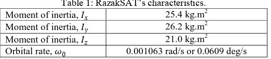
[image:4.612.169.447.589.650.2]The performance of the nonlinear observer designed in this work has been analyzed and validated using real sensors data from the RazakSAT satellite. RazakSAT is a Malaysian satellite which was launched into Low Earth Orbit near Equatorial in 2009. In the mission, the attitude was provided directly using sun sensor, one of the attitude sensor, while the angular velocity was provided by gyroscope sensor. The satellite’s characteristics of RazakSAT are given in Table 1, which was provided by Astronautic Technology SdnBhd (ATSB), the Malaysian company that responsible for RazakSAT’s mission.
Table 1: RazakSAT’s characteristics. Moment of inertia, 𝐼𝑥 25.4 kg.m2
Moment of inertia, 𝐼𝑦 26.2 kg.m2 Moment of inertia, 𝐼𝑧 21.0 kg.m2
Orbital rate, 𝜔0 0.001063 rad/s or 0.0609 deg/s
Figure 1: Real measurement of roll angle provided by attitude sensor.
Figure 2: Real measurement of pitch angle provided by attitude sensor.
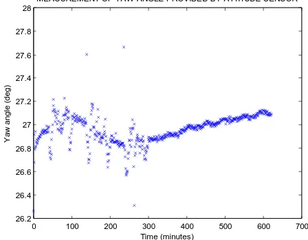
Figure 3: Real measurement of yaw angle provided by attitude sensor.
In order to validate and analyze the performance of the designed system, the estimated result is compared with the real sensor
0 100 200 300 400 500 600 700
67.4 67.6 67.8 68 68.2 68.4 68.6 68.8 69
Time (minutes)
R
o
ll
a
n
g
le
(
d
e
g
)
MEASUREMENT OF ROLL ANGLE PROVIDED BY ATTITUDE SENSOR
0 100 200 300 400 500 600 700
3 3.5 4 4.5 5 5.5 6 6.5
Time (minutes)
P
it
c
h
a
n
g
le
(
d
e
g
)
MEASUREMENT OF PITCH ANGLE PROVIDED BY ATTITUDE SENSOR
0 100 200 300 400 500 600 700
26.2 26.4 26.6 26.8 27 27.2 27.4 27.6 27.8 28
Time (minutes)
Y
a
w
a
n
g
le
(
d
e
g
)
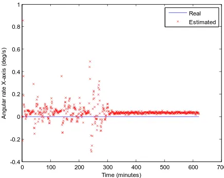
[image:5.612.189.413.482.657.2]the period analysed. While in the second half of the period, the estimated states are not scattered randomly as to the first half period. However, the estimated angular velocity around X-axis and Z-axis seem deviate from zero values of the real states measured by gyroscope. This deviation may be due to mis-modeling or the influence of unmodeled space environmental disturbance torque including aerodynamic, solar radiation pressure and Earth magnetic torques.
[image:6.612.194.409.538.713.2]Figure 4: Comparison between the estimated and the real angular velocity around X-axis.
Figure 5: Comparison between the estimated and the real angular velocity around Y-axis.
Figure 6: Comparison between the estimated and the real angular velocity around Z-axis.
0 100 200 300 400 500 600 700
-0.4 -0.2 0 0.2 0.4 0.6 0.8 1
Time (minutes)
A
n
g
u
la
r
ra
te
X
-a
x
is
(
d
e
g
/s
)
THE REAL AND ESTIMATED ANGULAR VELOCITIES AROUND X-AXIS
Real Estimated
0 100 200 300 400 500 600 700
-0.7 -0.6 -0.5 -0.4 -0.3 -0.2 -0.1 0 0.1 0.2 0.3
Time (minutes)
A
n
g
u
la
r
ra
te
Y
-a
x
is
(
d
e
g
/s
)
THE REAL AND ESTIMATED ANGULAR VELOCITIES AROUND Y-AXIS Real Estimated
0 100 200 300 400 500 600 700
-1.6 -1.4 -1.2 -1 -0.8 -0.6 -0.4 -0.2 0 0.2 0.4
Time (minutes)
A
n
g
u
la
r
ra
te
Z
-a
x
is
(
d
e
g
/s
)
THE REAL AND ESTIMATED ANGULAR VELOCITIES AROUND Z-AXIS
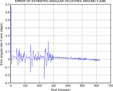
Figures 7, 8 and 9 show the plot error of the estimated angular velocities when compared to the real angular velocities measured by gyroscope of RazakSAT respectively around X-axis, Y-axis, and Z-axis. From all the three figures, it is also observed that behaviour of the error scattered randomly around zero value for about the first half of the analyzed period, while in the second half of the period, the estimated states are less scattered randomly as to the first half period. However, the error around X-axis and Z-axis is seem to have constant value about -0.05 deg/s for the second half of the analysed period. While the error around the Y-axis for the second half of analysed period decrease with a tendency to stabilize around a zero value. This could be arising from the mis-modeling factor which ignores the effects of the space environmental disturbance torque as described before.
Figure 7: Error of estimated angular velocity around X-axis.
Figure 8: Error of estimated angular velocity around Y-axis.
0 100 200 300 400 500 600 700
-1 -0.8 -0.6 -0.4 -0.2 0 0.2 0.4 Time (minutes) E rr o r a n g u la r ra te X -a x is ( d e g /s )
ERROR OF ESTIMATED ANGULAR VELOCITIES AROUND X-AXIS
0 100 200 300 400 500 600 700
-0.3 -0.2 -0.1 0 0.1 0.2 0.3 0.4 0.5 0.6 0.7 Time (minutes) E rr o r a n g u la r ra te Y -a x is ( d e g /s )
ERROR OF ESTIMATED ANGULAR VELOCITIES AROUND Y-AXIS
0 0.2 0.4 0.6 0.8 1 1.2 1.4 1.6 E rr o r a n g u la r ra te Z -a x is ( d e g /s )
[image:7.612.193.412.359.536.2]Figure 9: Error of estimated angular velocity around Z-axis.
Table 2 shows the Root Mean Squared Error (RMSE) of the estimated angular velocity compared to real angular velocity obtained by gyroscope measurement in RazakSAT mission. The result shows that the system is able to provide the information of angular velocity within 0.1 deg/s accuracy, which is suitable for moderate accuracy attitude determination mode such as during housekeeping and detumblingtask, but unsuitableforpointingmodethat requiresmorepreciseaccuracy such as during imaging task.
Table 2: RMSE of the estimated angular velocity.
States RMSE value
Angular velocity around X-axis, 𝜔𝑥 0.0825 deg/s
Angular velocity around Y-axis, 𝜔𝑦 0.0530 deg/s
Angular velocity around Z-axis, 𝜔𝑧 0.0982 deg/s
V.CONCLUSION
In this paper, a nonlinear observer to provide the angular velocity information in gyroless condition was designed and developed using Extended Kalman Filter algorithm. The system observability is first investigated to check the possibility of the nonlinear system states estimation by employing test rank using Lie derivatives technique. The rank test shows that the designed observer is observable everywhere, and hence can estimate the angular velocity from the Euler angles attitude information only without the gyroscopes. The performance of the designed observer by employing Extended Kalman Filter algorithm is then investigated and validated using real flight data of RazakSAT, the Malaysian satellite. The result shows that the system is able to provide the information of angular velocity within 0.1 deg/s accuracy, which is suitable for moderate accuracy attitude determination such as during housekeeping and detumbling mode. The designed observer can be used as an alternative or backup attitude determination system of a Low Earth Orbit satellite during unavailable gyroscope measurement due to faulty sensor or reduction of sensor hardware for cost reduction.
.REFERENCES
[1] J. L. Crassidis and F. L. Markley, “An MME-based attitude estimator using vector observations,” NASA Conf. Publ., p. 137, 1995. [2] J. A. Christian and E. G. Lightsey, “The sequential optimal attitude recursion filter,” pp. 1–20, 1965.
[3] H. E. Emara-Shabaik, “Spacecraft spin axis attitude,” IEEE Trans. Aerosp. Electron. Syst., vol. 28, no. 2, pp. 529–534, 1992.
[4] P. Appel, “Attitude estimation from magnetometer and earth-albedo-corrected coarse sun sensor measurements,” Acta Astronaut., vol. 56, no. 1–2, pp. 115– 126, Jan. 2005.
[5] B. Liu, Z. Chen, X. Liu, and F. Yang, “An efficient nonlinear filter for spacecraft attitude estimation,” Int. J. Aerosp. Eng., vol. 2014, pp. 1–11, 2014. [6] M. N. Filipski and R. Varatharajoo, “Evaluation of a spacecraft attitude and rate estimation algorithm,” Aircr. Eng. Aerosp. Technol., vol. 82, no. 3, pp. 184–
193, 2010.
[7] M. Fadly, O. Sidek, A. Said, H. Djojodihardjo, and A. Ain, “Deterministic and recursive approach in attitude determination for InnoSAT,” vol. 9, no. 3, 2011. [8] Y.-J. Cheon and J.-H. Kim, “Unscented filtering in a unit quaternion space for spacecraft attitude estimation,” 2007 IEEE Int. Symp. Ind. Electron., pp. 66–71,
Jun. 2007.
[9] M. C. Vandyke, J. L. Schwartz, and C. D. Hall, “Unscented Kalman filtering for spacecraft attitude state and parameter estimation,” pp. 1–13, 2004. [10] J.-H. Bae and Y.-D. Kim, “Attitude estimation for satellite fault tolerant system using federated unscented Kalman filter,” Int. J. Aeronaut. Sp. Sci., vol. 11,
no. 2, pp. 80–86, Jun. 2010.
[11] Y. Liu, X. Jiang, and G. Ma, “Marginalized particle filter for spacecraft attitude estimation from vector measurements,” J. Control Theory Appl., vol. 5, no. 1, pp. 60–66, Feb. 2007.
[12] Y. Yafei and L. Jianguo, “Particle filtering for gyroless attitude/angular rate estimation algorithm,” 2010 First Int. Conf. Pervasive Comput. Signal Process. Appl., pp. 1188–1191, Sep. 2010.
[13] Y. Cheng and J. L. Crassidis, “Particle filtering for sequential spacecraft attitude estimation,” 2000.
[14] J. L. Crassidis, F. L. Markley, E. G. Lightsey, and E. Ketchum, “Predictive attitude estimation using global positioning system signals,” in NASA Conference Publication, 1997, pp. 1–14.
[15] J. L. Crassidis and F. L. Markley, “Predictive filtering for attitude estimation without rate sensors,” J. Guid. Control. Dyn., vol. 20, no. 3, pp. 522–527, May 1997.
[16] M. D. Shuster, “A survey of attitude representation,” J. Astronaut. Sciense, vol. 41, no. 4, pp. 493–517, 1993. [17] M. J. Sidi, Spacecraft Dynamics and Control: A Practical Engineering Approach. Cambridge University Press, 2000. [18] J. L. Crassidis and J. L. Junkins, Optimal Estimation of Dynamic Systems. Boca Raton: CRC Press, 2004.
[19] M. M. Aly, H. a. Abdel Fatah, and A. Bahgat, “Nonlinear observers for spacecraft attitude estimation in case of yaw angle measurement absence,” Int. J. Control. Autom. Syst., vol. 8, no. 5, pp. 1018–1028, Oct. 2010.
[20] J. J. E. Slotine and W. Li, Applied Nonlinear Control. Englewood Cliffs: Prantice-Hall, 1991.
AUTHORS
First Author (Correspondence Author) – Nor HazaduraHamzah received his MSc in Mathematics from Faculty of Sciences,
Second Author – Prof. Dr. SazaliYaacobreceived his MSc in System Engineering at University of Surrey and PhD in Control
Engineering from University of Sheffield, UK in year 1987 and 1995, respectively. He is currently a Professor at University Malaysia Perlis. His research interests are in control, modelling and signal processing with applications in the fields of satellite, bio-medical, applied mechanics and robotics. ([email protected])
Third Author – Dr. HariharanMuthusamy,received his PhD in Biomedical Engineering from University Malaysia Perlis. He is
currently a lecturer at University Malaysia Perlis. His research interests are in control, modelling and signal processing with applications in the field of bio-medical system. ([email protected])