doi: 10.3389/fmars.2019.00424
Edited by: John Siddorn, Met Office, United Kingdom
Reviewed by: Masanao Shinohara, The University of Tokyo, Japan Stanley Kim Juniper, University of Victoria, Canada
*Correspondence: Bruce M. Howe [email protected]
Specialty section: This article was submitted to Ocean Observation, a section of the journal Frontiers in Marine Science
Received:31 October 2018 Accepted:05 July 2019 Published:02 August 2019
Citation: Howe BM, Arbic BK, Aucan J, Barnes CR, Bayliff N, Becker N, Butler R, Doyle L, Elipot S, Johnson GC, Landerer F, Lentz S, Luther DS, Müller M, Mariano J, Panayotou K, Rowe C, Ota H, Song YT, Thomas M, Thomas PN, Thompson P, Tilmann F, Weber T and Weinstein S (2019) SMART Cables for Observing the Global Ocean: Science and Implementation. Front. Mar. Sci. 6:424. doi: 10.3389/fmars.2019.00424
SMART Cables for Observing the
Global Ocean: Science and
Implementation
Bruce M. Howe1* , Brian K. Arbic2, Jérome Aucan3, Christopher R. Barnes4,
Nigel Bayliff5, Nathan Becker6, Rhett Butler7, Laurie Doyle8, Shane Elipot9,
Gregory C. Johnson10, Felix Landerer11, Stephen Lentz12, Douglas S. Luther13,
Malte Müller14, John Mariano15, Kate Panayotou16, Charlotte Rowe17, Hiroshi Ota18,
Y. Tony Song11, Maik Thomas19,20, Preston N. Thomas21, Philip Thompson22,
Frederik Tilmann19,20, Tobias Weber19and
Stuart Weinstein6on behalf of the Joint Task Force for SMART Cables
1Ocean and Resources Engineering, School of Ocean and Earth Science and Technology, University of Hawai‘i at M ¯anoa,
Honolulu, HI, United States,2Department of Earth and Environmental Sciences, University of Michigan, Ann Arbor, MI, United States,3Laboratoire d’Études en Géophysique et Océanographie Spatiales (LEGOS), Toulouse, France,4School of Earth and Ocean Sciences, University of Victoria, Victoria, BC, Canada,5SIN Medida Limited, Newbury, United Kingdom, 6Pacific Tsunami Warning Center, National Oceanic and Atmospheric Administration, National Weather Service, Honolulu, HI, United States,7Hawaii Institute of Geophysics and Planetology, School of Ocean and Earth Science and Technology, University of Hawai‘i at M ¯anoa, Honolulu, HI, United States,8Alcatel Submarine Networks, Hong Kong, Hong Kong, 9Rosenstiel School of Marine and Atmospheric Science, University of Miami, Miami, FL, United States,10Pacific Marine Environmental Laboratory, National Oceanic and Atmospheric Administration, Seattle, WA, United States,11Jet Propulsion Laboratory, California Institute of Technology, Pasadena, CA, United States,12Ocean Specialists, Inc., Stuart, FL, United States,13Department of Oceanography, Joint Institute for Marine and Atmospheric Research, School of Ocean and Earth Science and Technology, University of Hawai‘i at M ¯anoa, Honolulu, HI, United States,14Development Centre for Weather Forecasting, Norwegian Meteorological Institute, Oslo, Norway,15DRG Undersea Consulting, Inc., Morristown, NJ, United States,16GHD Consulting, London, United Kingdom,17Los Alamos National Laboratory, Los Alamos, NM, United States,18International Telecommunications Union, United Nations, Geneva, Switzerland,19Helmholtz Centre Potsdam, German Research Centre for Geosciences (GFZ), Potsdam, Germany,20Freie Universität Berlin, Berlin, Germany, 21Thomas Strategies, Menlo Park, CA, United States,22Sea Level Center, University of Hawai‘i at M ¯anoa, Honolulu, HI,
United States
from SMART cable data, and the societal, technological, and financial elements of realizing such a global network. Simulations show that deep ocean temperature and pressure measurements can improve estimates of ocean circulation and heat content, and cable-based pressure and seismic-acceleration sensors can improve tsunami warning times and earthquake parameters. The technology of integrating these sensors into fiber optic cables is discussed, addressing sea and land-based elements plus delivery of real-time open data products to end users. The science and business case for SMART cables is evaluated. SMART cables have been endorsed by major ocean science organizations, and JTF is working with cable suppliers and sponsors, multilateral development banks and end users to incorporate SMART capabilities into future cable projects. By investing now, we can build up a global ocean network of long-lived SMART cable sensors, creating a transformative addition to the Global Ocean Observing System.
Keywords: ocean circulation, ocean cabled observatories, submarine telecommunications cables, tsunami early warning, ocean observing, UN Joint Task Force, SMART subsea cables
THE SMART CABLES CONCEPT
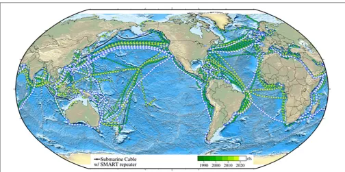
Deploying oceanographic sensors on new undersea telecommunication cables is a promising solution for obtaining the extensive, longitudinal, real-time data that are critical for understanding and managing urgent environmental issues such as climate change and tsunami hazard mitigation. Such sensors can provide important environmental data from sites in the deep ocean that are otherwise difficult and expensive to obtain in real-time and over decadal time scales. Suitable sensors are already deployed on dedicated cabled ocean research observatories, and with modest non-recurring engineering expenses, such sensors can be integrated in future telecommunications cables to create SMART cable systems (Science Monitoring And Reliable Telecommunications;Figure 1).
The SMART cables concept originated decades ago and has been demonstrated on a small scale by placing a few sensors at the end of disused cables, such as off Japan in the 1990s for detecting earthquakes and tsunamis. Modern fiber-optic cables, capable of delivering power and high bandwidth, have been used as part of dedicated sustained cabled observatories to obtain data on complex ocean systems beyond what is available from conventional methods, such as research vessels and fixed buoys (Favali et al., 2010). The first such cabled observatories were the 2006 coastal VENUS system (Tunnicliffe et al., 2008) and the regional NEPTUNE observatory operational in 2009 (Barnes et al., 2015; Best et al., 2015), now within Ocean Networks Canada (ONC). Similar observatories, tailored to national, scientific, and geographical needs, have included Japan – DONET and S-net (Kawaguchi et al., 2015; Kanazawa et al., 2016), United States – Ocean Observatories Initiative (OOI) and others (Massion and Raybould, 2006; Kelley et al., 2014;
Howe et al., 2015), China (Lu et al., 2015), and Europe (Best et al., 2014; Person et al., 2015). These developments have in turn fostered the evolution of progressively smaller, more precise
and reliable sensors (Schaad, 2009;Paros et al., 2012;RBR, 2017;
Delory and Pearlman, 2018).
Advocacy for the SMART cables concept began in earnest with a paper byYou (2010). In 2012, following workshops in Rome (2011) and Paris (2012), three United Nations agencies established the Joint Task Force (JTF) to facilitate development of the concept (the International Telecommunication Union (ITU), the World Meteorological Organization (WMO), and the Intergovernmental Oceanographic Commission of the United Nations Educational, Scientific and Cultural Organization (UNESCO/IOC). The initial few years of development of JTF were described by Barnes (2018) and details of the various workshops and publications are provided on the JTF web site: https://www.itu.int/en/ITU-T/climatechange/task-force-sc/ Pages/default.aspx.
Science Monitoring And Reliable Telecommunications cables represent a potential major new element in the Global Ocean Observing System (GOOS), and JTF, as it develops SMART cables, is engaging closely with the GOOS Framework for Ocean Observing (FOO1; Lindstrom et al., 2012). A core concept
of GOOS FOO is “Essential Ocean Variables” (EOVs): high impact, discrete, feasibly monitored observable attributes of the global oceans. SMART cables, by their nature as extensive, deep-ocean, high-data-rate observatories, directly address several of the GOOS EOVs. For example, ocean bottom pressure (OBP) was recently accepted as an emerging EOV, and SMART cables are potentially the most extensive and cost-effective source for such measurements. SMART cables also measure subsurface temperature, and the tsunami-measurement capabilities of SMART cables would address one aspect of the Sea Surface Height EOV. GOOS prescribes a phased approach for new ocean observing technologies, from concept to regional pilots through to global implementation. JTF is following this approach, taking steps to ensure that SMART cables and the
FIGURE 1 |Current and planned cables span the oceans, enabling the Internet and our society. As they are replaced and expanded over their 10–25 year refresh cycle, environmental sensors (pressure, temperature, acceleration) can be added to the cable repeaters every∼100 km, gradually obtaining real time global coverage (for clarity, repeaters are shown only every 300 km. rfs – year ready for service). Cable data: TeleGeography’s Telecom Resources licensed under Creative Commons ShareAlike. Permission obtained for use of figure.
data derived from them can be seamlessly incorporated in GOOS as part of a comprehensive Deep Ocean Observing Strategy (DOOS;Levin et al., 2019).
A central feature of the SMART cables concept is that it brings together two key themes of the 21st century: the increasing pressure for global connectivity and the urgent need for coherent, concerted global effort on climate change and ocean management. The market-driven investment in information infrastructure can be harnessed to achieve tangible, social benefits in climate and ocean science. The relatively modest suite of proposed instruments will help address many of the basic science and societal needs, and will also facilitate the monitoring of the physical integrity of the cable itself. The importance of such synergy is reflected in the themes of OceanObs’19 (e.g., the “Blue Economy” and “Ocean Discovery,” particularly in the deep oceans) and the United Nations’ Sustainable Development Goals (SDG 13 – Climate and SDG 14 – Oceans).
Joint Task Force and its industry partners recognize the need for funding sources to bear the development costs of integrating sensors into existing submarine cable components and the incremental capital expenditures associated with adding SMART capabilities to a telecommunications cable system. JTF’s next step is a wet demonstration/pilot project, in which sensor packages are included on a relatively short submarine cable using standard industry practices, with data retrieved in real-time over a minimum of 1 year. Multiple suitable cable projects are in the planning stages in the South Pacific, where JTF can validate not only the technical elements, but also the data management, regulatory
clearances, and funding mechanisms (e.g., multilateral development banks).
This paper first explains how SMART cables can improve our understanding of myriad ocean and geophysical processes, including ocean temperature, circulation, sea level rise, tides and wind waves, as well as tsunami modeling and seismology (see section “Improvements in Ocean Observing with SMART Cables”). The paper then details the practical aspects of creating such a network: what sensors SMART repeaters will use and how will they integrate into subsea telecommunications cable systems (see section “Technical Approach”); how the resulting data will be managed, distributed, and used (see section “Data Management and Users”); how the international SMART cables program will be overseen (see section “Program Management”); what legal and permitting considerations are relevant to SMART cables (see section “Legal Outlook”); what the costs of a SMART cable system are and what sources of financing there are to meet those costs (see sections “Cost Estimate” and “Financing”). Recommendations for OceanObs’19 to consider are given in section “Summary.” Cost elements and projections from year 1 through 25 are provided as a supplement.
IMPROVEMENTS IN OCEAN OBSERVING
WITH SMART CABLES
are temperature, pressure, and seafloor seismic acceleration. Importantly, as discussed in the previous section, the direct measurements and their derivatives respond directly to the GOOS need for greater attention to EOVs and the UN imperative to contribute to the SDGs. More broadly and in the future, the SMART cable infrastructure will provide a general interface into the deep ocean.
Oceanography
Oceans are currently monitored by in situ (ships, buoys, moorings, or floats) and remote sensing (satellite) techniques, yet the deep ocean and the important processes occurring remain undersampled and unobserved. Data from SMART cables would fill critical gaps in our existing monitoring systems, complement existing observations, increase our current level of understanding of the ocean, and improve our capability to predict its future evolution.
Ocean Temperature
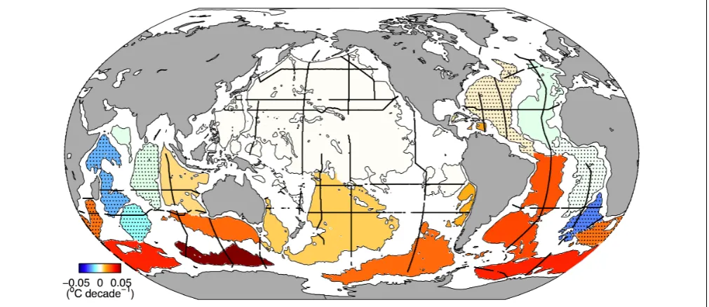
Antarctic Bottom Waters, which fill much of the deep oceans (Johnson, 2008) are warming, absorbing substantial amounts of heat, and contributing to sea level rise (Figure 2; Purkey and Johnson, 2010). In addition, the Atlantic meridional overturning circulation (AMOC) is changing (Smeed et al., 2018), and those changes are associated with variations in ocean temperature, air–sea heat flux, and sea level, suggesting that this full-depth ocean circulation feature is important in modulating regional and global climate.
There are now several trans-basin moored arrays monitoring the AMOC at different latitudes (McCarthy et al., 2015;Lozier et al., 2017; Meinen et al., 2017), but outside of the Atlantic, oceanographers currently rely primarily on Global Ocean Ship
(GO-SHIP) repeated transoceanic hydrographic sections (Talley et al., 2016) to monitor the deep ocean water properties and circulation variations, along with a few time series stations (Lukas et al., 2001) and deep instruments on moorings both regional (McKee et al., 2011) and global (Send and Lankhorst, 2011) in scope. Deep Argo floats capable to a depth of 6,000 m have been developed, with a few regional pilot arrays already deployed or planned (Jayne et al., 2017), and a global network envisioned (Johnson et al., 2015). Changes in the deep ocean, however, remain undersampled (Johnson et al., 2015). SMART cables, with transoceanic sampling of temperature in the bottom boundary layer at roughly 50 km resolution, would complement other data sets that facilitate investigation into water temperature variability, trends, and circulation (together with SMART cable pressure sensors). SMART cable temperature sensors would provide much closer spatial sampling than either Deep Argo at 500 km nominal density (Johnson et al., 2015), transoceanic arrays moorings that are often much farther apart in the ocean interior (McCarthy et al., 2015; Lozier et al., 2017; Meinen et al., 2017), or the even sparser OceanSites moorings (Send and Lankhorst, 2011). They would provide much better temporal resolution than either the 10–15 day Deep Argo sampling or the decadal repeats of GO-SHIP transoceanic hydrographic sections (Talley et al., 2016).
Ocean Circulation, Sea Level Rise, and Mass Distribution
Since 2004, the RAPID/MOCHA array has been providing estimates of the AMOC at 26.5◦
[image:4.595.46.552.443.662.2]N by estimating the pressure gradient between the western and eastern continental slopes (McCarthy et al., 2015). From the AMOC strength, the climate-relevant meridional heat transport and its variation can
FIGURE 2 |Deep basin (thin solid lines) average warming rates below 4,000 m from the 1990s to the 2000s (◦
also be inferred, because a strong linear relationship exists between ocean volume and heat transports, at least at 26.5◦
N (Johns et al., 2011). SMART cables would complement and extend the existing AMOC estimates in two ways. First, OBP measurements on cables spanning an entire ocean basin could measure the pressure differences at many depths between the western and eastern boundaries of the basin. The pressure differences are directly related to the transports at those depths, as illustrated in Figure 3. Both the upper and lower limbs of the dominant geostrophic component of AMOC transport can be estimated in this way (Hughes et al., 2013, 2018; Elipot et al., 2014). Second, multiple cross-basin transects by SMART cables at different latitudes would allow a division of major ocean basins into boxes. Geostrophic transports across box boundaries could then be estimated from OBP observations as just described, allowing the mass balance of individual boxes to be calculated. These box models would finally allow a quantification of the long-term mass evolution in an ocean basin, based on unaliased measurements.
[image:5.595.45.292.542.631.2]Global warming has caused global mean sea level to rise at a rate of 3.0 ± 0.4 mm/year since 1992 (Figure 4), with an estimated current acceleration of 0.084 ± 0.025 mm/year2 (Nerem et al., 2018). This will lead to a sea level rise of approximately 65 cm by 2100. Because individual contributions to sea level change, such as barystatic (mass changes, e.g., due to melting land ice) and steric (expansion of water, e.g., due to warming) effects in the ocean, as well as Earth-produced eustatic (changes in ocean volume) and isostatic (changes in height of land) effects, vary considerably across the oceans, sea level rise is not homogeneous. Sea level variability patterns can be determined by various measurement techniques and sensors, e.g., radar altimetry and tide gauges. The identification of individual contributing effects, however, requires complementary observation methods at each location. OBP observations provide the amount of local barystatic sea level change. SMART cables would provide a network of long-lasting, temporally unaliased OBP sensors that could be quite dense in some basins and unaliased along the cables. In conjunction with sea level observations by altimetry, or density field observations by Argo floats, for instance, the OBP measurements would enable
FIGURE 3 |Schematic of the geostrophic relationship between OBP (as measured by SMART pressure sensors, green dots/cables) at the western boundary of an ocean basin relative to the eastern boundary, given a net transport between the boundaries as indicated by the arrows. At the deepest depths, pressure differences on the sides of seafloor mountain ranges come into play and will also be captured by SMART cable OBP observations. Adapted from C. Hughes. Permission obtained for use of figure.
separation of the steric and barystatic contributions to sea level change at a particular location, whose differentiation is required to understand the causes of sea level rise and thus for reliable sea level projections.
The satellite gravity missions – GRACE (Tapley et al., 2004) and its successor GRACE-FO (Flechtner et al., 2016) – provide measurements of the temporally varying gravity field, which can be interpreted as OBP and ocean mass. Such satellite data, however, are aliased by short-scale processes that cannot be resolved in a global gravity field due to the horizontally integrating nature of the space-based gravity measurement itself, and the characteristics of the satellite orbits, e.g., orbit period, repeat period, inclination, and ground distance between successive orbits. Hence, the data have to be “corrected” by a de-aliasing procedure, involving parameters for oceanic tides, Earth tides, short-term atmospheric pressure variability and short-period oceanic barotropic oscillations (Rietbroek et al., 2006). The quality of the resulting products is one of the main limiters of current and future gravity field missions (Panet et al., 2013). Local alterations of gravity are caused by changes in the vertically integrated mass distribution and a consequence of mass transport in the solid Earth, cryosphere, atmosphere, and ocean (Kelley et al., 2014; Dobslaw et al., 2017). Variations of oceanic mass are reflected in situby OBP changes. Thus, OBP observations from SMART cables can significantly contribute to the improvement of the GRACE-derived oceanic products in two complementary ways.
FIGURE 4 |Sea level trend in mm/year as derived from TOPEX, Jason-1, and Jason-2 for 1992–2018. Blue lines denote possible future SMART cable routes. Altimetry data is courtesy of NOAA/NESDIS Center for Satellite Applications and Research, and provided by the NOAA Laboratories for Satellite Altimetry (NOAA/NESDIS, 2018). Permission obtained for use of figure.
FIGURE 5 |Influence of data assimilation of synthetic SMART cable OBP observations. Reduction of root-mean-square difference between OBP simulated by ROMS and MPIOM for April 2014. Blue lines indicate possible future SMART cable transects. Permission obtained for use of figure.
Ocean Surface (Barotropic) Tides
Simulation of the gravitationally forced surface (barotropic) tides has now become quite accurate even without assimilation of satellite altimetric data. Forward tide models now routinely capture 90% or more of tidal sea surface height variance (Arbic et al., 2004;Egbert et al., 2004).
This success does not mean that further study of the tides is now of minimal value. On the contrary, there are still a number of poorly understood or poorly described tidal phenomena, such as the lesser tidal constituents, seasonal variability of all constituents, non-linear constituents, rapid variation of constituent structure in shallow water, and shifting sinks of energy as the global environment changes. Although these factors exhibit small amplitudes, their global distributions are sought due to their impacts on such phenomena as internal tide generation, deep ocean mixing, paleotide descriptions, and Earth structure, as well as due to their utility in defining the tidal “correction”
that must be applied to satellite altimetry data to extract the sub-diurnal variability of ocean circulation features as well as long period sea level rise.
Ocean bottom pressure observations provide one of the better tools for exploring the finer details of the barotropic tides, because the broad band, non-tidal “geophysical noise” within which the tides are embedded is much weaker at the seafloor than at the sea surface (Ray, 2013). The geophysical noise that limits the utility of satellite observations andin situ
coastal sea level observations arises from surface-intensified processes such as internal waves, mixed-layer currents, and coastal-trapped edge waves.
barotropic tides do vary on seasonal timescales (Müller et al., 2014), and even on secular timescales at the continental coasts (Ray, 2006;Müller et al., 2011). Detection of secular changes in the open ocean tides is less clear (Müller et al., 2011;Zaron and Jay, 2014;Schindelegger et al., 2018).
As an example of time-varying barotropic tide signals that could be seen by SMART cables, we can estimate tidal seasonal variability along the cable paths, using simulated hourly OBP samples from high-resolution global ocean models that are forced simultaneously by atmospheric fields and the astronomical tidal potential (Arbic et al., 2010, 2012, 2018; Müller et al., 2012, 2014;Rocha et al., 2016). The amplitude of the seasonal variability of the principal lunar semi-diurnal tide M2 from
the Müller et al. (2014) simulation is given in Figure 6. The range is from 0 to 0.5 cm, which is measurable by the OBP sensors envisioned within the SMART cable repeaters. There are currently no global-scale measurements for models of seasonal tidal variability. SMART cable measurements of OBP would allow unique, basin-scale quantification of barotropic tidal variability over a wide range of timescales, thus providing ground truth for secular and seasonal changes to tidal correction models used in altimetry and gravimetry.
Wind Generated Waves, Microseisms, and Infragravity Waves
Wind-generated waves at periods shorter than 30 s are ubiquitous at the ocean surface. In the open ocean, they play a crucial role in the exchange of heat and gases between the ocean and the atmosphere (Hasselmann, 1991), and they can be a major
natural hazard at the coast (Hoeke et al., 2013). Because the wind-generated waves have wavelengths far shorter than the average ocean depth, these waves cannot be measured at the seafloor deeper than 1,000 m and satellites or floating buoys are used to measure them. The popularity of real-time wave observations from near-coast anchored buoys to mariners and surfers (such as the Coastal Data Information Program;Thomas et al., 2015) suggests that OBP observations on SMART cables on the continental shelves and upper slopes could provide useful information on wave amplitudes, periods, and even directions to the local coastal populace, especially in regions where wave buoys have not yet been deployed.
Microseisms constitute the principal seismic noise source on Earth. Wind waves breaking and interacting in the shallow waters of the continental shelves, as well as in the open ocean, generate seismic noise in the period band of the wind waves and at shorter periods (2–20 s). The larger, but termed “secondary,” microseism generation mechanism (Longuet-Higgins, 1950) in the deep ocean is from opposing trains of ocean waves, which interact and generate a pressure signal at the seafloor with half the period of the interacting waves. This pressure signal generates seismic waves in the seafloor that can be observed and used for analysis even at the farthest reaches from the oceans in central Asia (Bromirski et al., 2005; Ardhuin et al., 2011; Chen et al., 2015;Butler and Aucan, 2018). These observations improve our understanding of both seismic waves in the seafloor and waves at the ocean surface.
[image:7.595.44.552.412.678.2]Infragravity (IG) waves are surface waves with periods ranging from minutes to hours. Nonlinear interactions between wind
waves in the open ocean and at the coasts generate IG waves at periods from 0.5 min to many tens of minutes. IG waves appear as either “free” or “bound” waves (Herbers and Guza, 1994; Herbers et al., 1995), where the bound waves are tied to underlying groups of wind waves and become free at the shoreline where the short wind waves break (Bertin et al., 2018). A small fraction of the resultant free IG energy leaks into the open ocean where it can spread for thousands of kilometers, with horizontal wavelengths of up to 10s of kilometers and heights of up to 10s of centimeters with significant seasonal variability, as seen in Figure 7(Aucan and Ardhuin, 2013). IG waves at longer periods up to hours have also been identified and appear to be forced by the surface barotropic tides and solar modes of oscillation (Chave et al., 2019). Given the size and wavelength of these IG waves, they are a source of alias noise in satellite measurements of sea surface elevation. Thus, a better understanding and modeling of the temporal and spatial variations of the IG waves could improve the processing of satellite altimetry data (Ardhuin et al., 2014).
Observations on wind-generated waves on the shelves, together with observation of IG waves and microseisms in the deep ocean on SMART cables have the potential to inform us about energy flow from the wind and tides into the deep ocean, as well as the source of Earth’s “hum” at the same frequencies, a topic of considerable interest to seismologists using
Earth’s vibrations to explore its structure (Nawa et al., 1998;
Rhie and Romanowicz, 2004;Webb, 2008). OBP measurements on SMART cable repeaters would contribute significantly to this purpose since the number of ongoing OBP sensors is so small (currently tens of sensors versus the potential of many hundreds of sensors on SMART cables).
Tsunami Monitoring and Warning
[image:8.595.49.550.364.679.2]One of the most pressing issues in the tsunami warning community concerns the ability to distinguish destructive tsunamis from those measurable on sea-level gauges but which do not pose a hazard along distant coastlines (Angove et al., 2019). Since the US tsunami warning system began in 1949, 75% of the evacuations of Hawaii’s coastlines have been unnecessary, with direct and indirect costs of millions or tens of millions of dollars per event. This is also true for other coastlines in the Pacific basin and elsewhere. In an attempt to alleviate this problem, NOAA’s Pacific Marine Environmental Laboratory (PMEL) developed the Deep-Ocean Assessment and Reporting of Tsunamis (DART) system (Paros, 2011; Bernard and Titov, 2015) which consists of an OBP sensor that communicates via an acoustic modem with a surface buoy that in turn relays the pressure measurements through the IRIDIUM satellite constellation. Prior to the development of the DART system, warning systems had to rely on tide gauges and coastal
observations when evaluating the potential destructiveness of a tsunami on distant shores. As tsunami height can be strongly affected by nearshore bathymetry and harbor resonance, reliance on coastal observations coupled with the assumption of worst-case scenarios made unnecessary evacuations inevitable. The main limitations of the DARTs are that they require their own power source, need maintenance every 2–3 years, and their availability is reduced significantly by destructive weather and, in some regions, vandalism. Compared to DARTs, SMART cable-based pressure sensors offer much denser sampling and effectively zero maintenance costs after deployment.
An even greater challenge is warning in the near field, i.e., coastal areas directly adjacent to the earthquake rupture. The time between the occurrence of the earthquake and the arrival of the tsunami wave can be as short as 5 min, and in many cases, the tsunami is exacerbated by a sudden co-seismic subsidence of the coast by up to 1–2 m. In all recent catastrophic tsunamigenic earthquakes, fatalities due to the near field tsunami have dominated the overall death toll. Third generation and older DART buoys have to be placed too far from the coast to be helpful for near field warnings due to the necessity of separating in time the pressure fluctuations caused by the tsunami wave from the seismic disturbance caused by the seismic (seafloor) surface wave. SMART cables and fourth generation DART buoys offer higher sample rates, which can separate these two types of disturbances by frequency filtering.
Perhaps the largest uncertainty tsunami warning systems face is in the determination of the source. As some 72% of tsunamis in the historical record are generated by the static seafloor displacement associated with large submarine earthquakes (the remainder by landslides, volcanoes and others), tsunami warning systems have focused on real-time seismology to facilitate rapid tsunami hazard warnings. Until the last decade, the Pacific Tsunami Warning Center (PTWC) based such warnings purely on the earthquake’s location and magnitude. However, these quantities alone are not sufficient to precisely assess the effects of a tsunami. As a result, over-warning or unnecessary warnings have been a flaw of whole-ocean warning systems since their inception. Recent advances in computational seismology, such as the ability to rapidly obtain the centroid moment tensor (CMT; Kanamori and Rivera, 2008;Duputel et al., 2012), have enabled the PTWC and other tsunami warning centers to generate whole-ocean forecasts with sufficient accuracy to be of service to emergency management systems. A robust CMT yields an authoritative assessment of the earthquake’s magnitude and rupture orientation, subject to an inherent ambiguity between the fault and auxiliary plane (perpendicular to the fault plane and slip vector). It also helps fix the fault geometry for a finite-fault model (Ammon et al., 2005; Weinstein and Lundgren, 2008) which gives the distribution of displacement on the fault plane. From this it is normally straightforward to calculate the sea-floor displacement, which is crucial for determining the overall size of the tsunami and the areas worst affected. A special case is represented by so-called tsunami earthquakes, which are earthquakes that produce tsunamis much larger than expected from their moment magnitude (Kanamori, 1972). Recent examples include the 2006 Java and the 2010 Mentawai
earthquakes. Shaking in these earthquakes is strongly subdued, meaning that the tsunami hits an unprepared population if there is no systematic warning.
The tsunami excitation can be further exacerbated by displacement along splay faults and triggered submarine landslides (e.g., Tappin et al., 2014) which are very difficult to detect by seismology alone. SMART cables can help mitigate this issue by providing arrays of pressure sensors, which allow an accurate assessment of the tsunami wave field as it propagates. Currently there are only some 70 or so deep ocean sensors (e.g., DARTs and DONET, S-net, ONC and OOI cabled observatories) permanently in operation and the vast majority of them are in the Pacific Basin. Placing pressure sensors on SMART cables could increase that number well into the hundreds or thousands (Figure 8). This additional near-real-time information can be used to validate and/or revise forecasts making tsunami warnings for areas>1,000 km from the earthquake more precise and greatly reducing the potential of unnecessary warnings and evacuations.
In addition to pressure sensors, SMART cables are envisioned to include strong-motion instruments (accelerometers), which measure the motion of the seafloor during an earthquake. With a few exceptions, currently all seismometers and strong-motion instruments are land-based, resulting in a one-sided view of subduction zone earthquakes. Accelerometers on SMART cables would fill in the gaps in the global seismic network (GSN) by acquiring data all along their routes, including in some cases, as they cross subduction zones, the source of the great earthquakes that generate ocean-crossing destructive tsunamis. Having a SMART cable with accelerometers near a submarine earthquake (i.e., having at least one sensor package within 100 km, although more distant sensors also significantly contribute) would allow for faster, more accurate hypocenter locations, magnitude estimates, CMT calculations, and finite-fault determinations. This additional information will speed up the process and improve the precision of tsunami wave height propagation models.
The PTWC has performed preliminary calculations as to how SMART cables can improve the tsunami warning system. Figure 9shows the routes of five hypothetical cables that contain OBP sensor/seismometer packages and the division of the world’s subduction zones into potential epicenters of great earthquakes. The routes chosen are hypothetical SMART cable routes and are not specifically based on any existing telecommunication cable route. The instrument packages are spaced 500 km apart and the calculations assume 688 potential earthquake centers located every 120 km on the world’s subduction zones.
Pacific Tsunami Warning Center has estimated the potential impact of SMART cables on the speed with which an earthquake hypocenter might be determined. Five stations must detect the P-wave and the largest azimuth gap between any two (azimuthally) neighboring stations with respect to the hypocenter must be less than 180◦
FIGURE 8 |Global map of∼1 million km of operational submarine telecommunications cables (green present, white in progress/planned; SMART repeaters shown every 300 km; rfs – year ready for service), historical earthquakes (red), and DART tsunami buoys (yellow triangles). Cable data: TeleGeography’s Telecom Resources licensed under Creative Commons ShareAlike; DART Buoy locations: NOAA National Data Buoy Center; Seismic data: USGS Earthquake Catalog. Permission obtained for use of figure.
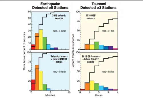
SMART cables in Figure 9. The resulting distribution of time-to-detection is shown in Figure 10(left). The inclusion of just five SMART cables has the potential to speed up Pacific-wide earthquake epicenter determinations by an average of∼21%.
Similarly, we calculated the reduction in latency in tsunami detection that is achievable with OBP sensors, following a tsunamigenic earthquake. Using the 688 epicenters inFigure 9, tsunami travel-times are computed from each epicenter to the set
FIGURE 9 |Hypothetical cable routes and SMART repeater locations (red dots) used in tsunami simulations. Also shown are potential trench axis earthquake epicenters (blue circles). Permission obtained for use of figure.
of OBP sensors received by PTWC with and without the OBP sensors associated with the SMART cables. With SMART cables in place, the time required to observe the tsunami arrival at three or more OBP sensors is reduced by∼25% (Figure 10, right).
Specifically, the four charts inFigure 10compare detection time for earthquakes (left) and tsunamis (right), first using only those sensors available in 2016 (top), and then using existing sensors augmented with simulated data from future SMART cable sensors (bottom). Detection of an earthquake – meaning reception on≥5 seismic instruments – is reduced from 2.4 to 1.9 min, or from an average of 2 min 24 s down to 1 min 54 s, which is a 21% reduction. Thirty seconds is an eternity in earthquake detection and warning.
FIGURE 10 |Comparing time statistics for cases without (top row) and with SMART sensors (bottom row). Left column:≥5-Station P-wave reception time with azimuthal gap<180◦, for trench axis sources. Right column: Time to detect and transmit tsunami data, for OBP signals detected. Permission obtained for use of
figure.
The minimum time required for earthquake location and time required to observe a tsunami at three or more pressure sensors would be further reduced if more repeaters were equipped with SMART capability, reducing the interval between sensors from 500 to 50 km. To balance detection speed and cost, SMART-enabled repeaters could be deployed more densely near the coast and at greater intervals farther away.
Even larger gains, particularly for the near field, are possible for telecommunications cables running parallel to the coast, as they would provide several measurements from the near-source region, and immediately would constrain the lateral extent of any rupture. Even essential improvements in earthquake early warning, e.g., alerts ahead of strong shaking, might become feasible, depending on the exact position of the cable. The coast-parallel cable does not need to run in close proximity to the coast on the continental shelf but can be in deep water seaward of the trench.
To demonstrate the feasibility of SMART cables for tsunami early warning, the 2011 Tohoku-Oki earthquake and tsunami have been simulated with three hypothetical SMART cables from Tokyo to Oregon, Hawaii, and Auckland, respectively (Figure 11). We show that with these hypothetical cables, the
2011 Japanese tsunami could have been detected and its height confirmed within a few minutes after the earthquake and about 20 min earlier than was possible with the nearby DART buoy (Song et al., 2012). This would have provided enough time for warning the coastal communities. While the S-net early warning cable system mentioned above was specifically built to do this, this could apply just as well to other similar regions, such as the margin of South America.
Seismology
FIGURE 11 |Simulation of the 2011 Japanese tsunami with three hypothetical SMART cable routes: Tokyo to Oregon, Hawaii, and Auckland. Permission obtained for use of figure.
seismologists, as the elastic waves in the solid Earth easily couple into the water layer. They are particularly suitable for studying lithospheric structure and lithosphere-asthenosphere interactions with seismic surface waves.
As an example of the many possible applications, we focus on global body wave tomography as an example to illustrate the potential of data collected from SMART cables for improved sampling of parts of the Earth structure previously poorly illuminated due to the heterogeneous distribution of both earthquakes (largely at the margins of tectonic plates) and sensors (mostly on-land or near shore) (Figure 12A).Figure 12Bdepicts a slice through a 3D global model of seismic velocities, derived through tomographic inversion of travel times from the sources to the receivers illustrated inFigure 12A. Here, the intensity of color indicates a change in the velocity model, driven by the data, from the 1D radial ak135 reference model (Kennett et al., 1995). White regions indicate no change from the starting model. Because of reduced coverage below the oceans, it is difficult to say whether these are due to (expected) greater homogeneity
below the ocean plates or because of lack of data in these places, hampering our ability to make robust geodynamic interpretation. The addition of SMART cable seismic sensors will significantly enhance the sampling of the Earth by augmenting existing ray paths of seismic propagation.
FIGURE 12 | (A)Distribution of global earthquakes (red) and existing seismic sensors (green) used in the derivation of the SALSA3D model.(B)Global seismic velocities at a 222 km depth in the 3D tomographic “SALSA3D” P-wave model shown as perturbation from the 1-D starting model (Begnaud et al., 2011;Ballard et al., 2016). Permission obtained for use of figure.
their sizes, which can retrospectively even benefit older events. The SMART cables will reduce detection thresholds not only for small events in proximity to the cables, but also for distant events whose signals can be enhanced by linear array methods using the new sensors.
Many large, destructive earthquakes occur in nearshore environments, where oceanic and continental lithosphere converge. Such plate interactions often occur offshore, hence on-shore seismic networks are some distance from the source, and provide a one-sided distribution of receivers, poorly constraining the location. If a nearby SMART cable exists, it
FIGURE 13 |Seismic ray coverage for two hypothetical sources in a block of the Pacific region. Coastlines are shown on the top. Sources are indicated as red stars in Cook Inlet, Alaska, and Korea. Rays, traced through the SALSA3D global P-wave model (Begnaud et al., 2011;Ballard et al., 2016) appear as curved lines from sources to receivers. Left: sampling of the Earth using today’s GSN (blue circles). Right: greater sampling afforded by addition of notional SMART cables, with 75-km sensor spacing (green circles;Ranasinghe et al., 2018). Permission obtained for use of figure.
and then, by applying tomographic analysis at a much smaller scale than described above estimate the material properties in the forearc. In turn these can help us to enhance our understanding of the seismogenic potential of the margin.
TECHNICAL APPROACH
SMART Cable Concept Requirements
The fundamental premise of SMART cables is integrating environmental sensors into commercial submarine telecommunications cables. The crucial objectives are: (a) to obtain long term measurements of ocean bottom temperature, pressure, and three-axis seismic acceleration, (b) to have little or no impact on the operation of the telecommunications system that hosts the sensors, (c) to require no special handling or deployment methods, and (d) to be sufficiently reliable that 95% of all sensors operate for a minimum of 10 years.The Global Subsea Fiber Optic Network
More than 1.1 million km of cable and 400 independent subsea cable systems are operated, maintained, and periodically renewed by the telecommunications industry. A full technical description of modern cable systems is given by Chesnoy (2016). Cables are installed across the North Atlantic, North Pacific, through the Mediterranean and Indian Oceans, through the Middle East, around South America and Africa, and throughout Oceania. Replacement or expansion cables are installed at intervals ranging from a few years on major routes to 10–15 years on minor routes. Thus, there is an opportunity on most or all cables to introduce sensor capabilities within the next 5–10 years.Subsea Cables
A subsea fiber optic communications system comprises the cable (with varying layers of protection depending on water depth, seabed conditions, and potential risks), pressure housings containing erbium doped fiber amplifiers (EDFAs) (referred to as “repeaters”) spaced at intervals from 60 to 150 km, power feed equipment (PFE) that delivers a controlled direct current to the repeaters through the cable’s single electrical conductor, and terminal station equipment (TSE) to transmit and receive
signals on the optical fiber strands within the cable. Systems may include branching units (BUs) to provide connections to locations along the main cable route. Lengths range from less than 100 km to greater than 10,000 km. Regional systems with lengths up to 2,500 km are ideal for the inclusion of sensor capabilities because these systems have sufficient design margin and can usually accommodate additional fibers to carry sensor data. Ocean spanning cables of 6,000 km or more are the most challenging. Successful operation of shorter SMART cables will be needed before sensor functions can be introduced into the longest cables.
The repeater is housed in a cylindrical pressure vessel typically 30 cm in diameter and 60–120 cm in length. Together with couplings and strain relief, the entire repeater assembly is 3– 5 m long (Figure 14). The repeater houses EDFAs, which provide signal gain. The current generation of cable systems can have up to 16 fibers (eight bi-directional pairs) and work is underway to allow higher numbers of fibers.
From Single-Purpose Cables to SMART
Cables
Functional elements to be added into the repeater include the sensors themselves, digital signal processing, an embedded processor, an Ethernet data switch, fiber optic transceivers, and power supplies. The most feasible way to transmit sensor data is to dedicate one fiber pair, although this reduces the overall capacity of the cable system. Options for embedding sensor data into the signal on a fiber pair dedicated to telecommunications are also under consideration.
FIGURE 14 |Illustration of a repeater housing showing two possible sensor mounting locations:(A)on the end of repeater housing under the bell housing or(B)in an external pod. Accelerometers are mounted inside the pressure housing(C). Permission obtained for use of figure.
sensors must be isolated from high voltages present within the repeater and must be fail-safe so that the normal operation of the repeater cannot be impacted by faults in the external sensors. All of this must be done in a manner that is consistent with the 25-year expected operating life and 8,000 m deployment depth of a commercial repeater. Work is underway to identify and address these issues but will ultimately require the involvement of repeater manufacturers’ development teams. Pressure sensor drift remains problematic and although a method of correction has been demonstrated (Wilcock et al., 2017), the resulting form factor is not yet suitable for incorporation into a repeater. The use of quartz pressure sensors without correction remains the best solution currently available.
An alternative, interim solution for adding SMART capabilities to commercial cable projects is to attach a set of SMART repeaters to a backbone cable by means of a BU. The backbone cable contains conventional telecommunications repeaters from which optical fibers and a power feed conductor “branch off ” to a dedicated science cable that is independent of the telecommunications system. This arrangement has essentially no impact on the design of the backbone telecommunications system. The only non-standard component is the dual conductor cable required between the BU and shore station, although such a cable has been successfully deployed on multiple prior projects. The BU approach is attractive as an interim SMART cable demonstration because it avoids planning and technical complications of integrating SMART capabilities into tightly designed, standardized telecommunications repeaters. In a BU system, the power utilization, mechanical size, and reliability of the SMART sensors need not conform to the constraints of a fully functioning repeater. This flexibility can be used to prove SMART repeater designs, try other types of sensors, and demonstrate the data gathering and data management processes prior to approaching telecommunications and cable providers with the
proposal for integration into the repeaters of the backbone cable. This interim variant is called a “wet demonstrator” (Joint Task Force, 2015b; Joint Task Force Engineering Team, 2016a,b). The chief drawback of this approach is the SMART functions are not hosted directly on the repeaters but rather are connected to a separate cable which does not provide telecommunications functions; while some costs can still be shared, this reduces the synergy between the telecommunications and science investment.
Previous Work
The earliest example of a submarine cable-based observatory is the Geophysical and Oceanographysical-Trans Ocean Cable (GeO-TOC), which was installed in 1997 midway between Guam and Japan using the retired TPC-1 communications cable (Kasahara et al., 1998). The GeO-TOC system anticipated the development of SMART cables by almost two decades yet included all essential SMART cable features: a three-axis accelerometer, pressure sensor, and precision thermometer. These were incorporated into an in-line pressure housing which was deployed from a cable ship in a conventional manner.
In the first decade of the 2000s, attention shifted to regional scale observatories such as NEPTUNE/ONC in Canada, DONET in Japan, and the OOI Regional Cabled Array (RCA) in the United States (Hazell et al., 2007; Kawaguchi et al., 2008;
Following the Tôhoku earthquake and tsunami of 2011, Japan undertook rapid development of a large-scale network of subsea seismic and pressure sensors (Kanazawa, 2013;Kanazawa et al., 2016). The resulting S-net system incorporates many of the functions essential to a SMART cable. The overall deployment consists of 150 observation nodes along 5,700 km of cable divided into six independent subsystems. Each observation node consists of an underwater housing containing seismometers and pressure sensors connected in-line with a telecommunications cable. The result closely resembles a telecommunications repeater, however, as the rigid case has a length 1 m greater than that of a typical repeater, modifications to conventional cable laying equipment are required. Nevertheless, S-net provides evidence that SMART cables are close to being feasible using currently available technology.
Another in-line ocean bottom seismometer was developed by the University of Tokyo (Shinohara et al., 2014). This design is more compact than the S-net observatory at 50 cm long and 13 cm in diameter. A total of four units and 25 km of cable were deployed off the west coast of Awashima in 2012 using conventional cable laying equipment. Ethernet switches and optical transceivers are employed, an approach which could also be applied to SMART cables. In 2015, this was commercialized using an industry standard repeater housing and deployed off Sanriku with three nodes and a length of 105 km. This design is commercially available and could be employed as an initial demonstration to build further confidence in the feasibility of SMART cables (Shinohara et al., 2016).
Sensors
The SMART cable sensor suite is comprised of just three sensors for temperature, pressure and acceleration, chosen based on the science described above and for engineering simplicity, especially important in facilitating the overall acceptance of the SMART concept by industry. These are well proven sensors, long used in oceanography and cabled observatories and early warning systems. Temperature is a local measurement while pressure and acceleration provide remote sensing of the entire water column and remote events and the intervening media. Detailed requirements for the SMART sensors are given in the several white papers (Lentz and Phibbs, 2012;Joint Task Force, 2015a).
Temperature sensors can meet the required initial accuracy of 1 mK and stability of 2 mK/year. They need to be mounted some distance from the repeater, a “heat island” dissipating∼50 W; this can be done in a sheath meters from the repeater (Figure 14).
Three-axis accelerometers, also called strong motion sensors or seismometers, reside inside the repeater housings; indeed, simple accelerometers are included in one supplier’s repeaters for engineering purposes (Xtera, 2016). The key requirements for SMART accelerometers are a noise level less than 2 ng at 1 Hz and a sample rate of 200 Hz.
Pressure sensors also need to reside external to the repeater housing (see Figure 14) with access to local ambient pressure; there is typically a dedicated internal temperature sensor immediately next to the sensing element to account for temperature dependence. The main requirements are: depth rating to 7,000 m (with overpressure tolerance to 8,000 m,
the standard telecom rating); short term accuracy 1 mm water relative to recent measurements; 0.01% of full range absolute; and maximum allowable drift during a settling-in period of 20 cm/year.
Sensors meeting these requirements will be used for the first SMART systems. It is recognized though that sensors are continually improving, and different observables may be desired. In the first category, much effort has been devoted to removing long term drift from pressure sensor data with linear and exponential terms (Watts and Kontoyiannis, 1990;
Polster et al., 2009). A newin situcalibration method has been devised that largely removes sensor calibration drift, reducing it from ∼10 cm/year (initial) to ∼1 mm/year, less than the nominal 3 mm/year sea level rise. In this “A-0-A” method, the pressure sensor is occasionally switched from Ambient water pressure to “0” internal case pressure, the latter nominally 1 atm measured with a barometer (Wilcock et al., 2017). While the current prototypes are too bulky, and the mechanical valving is cumbersome, it is worthwhile to monitor the development of the technology.
In the second category of other observables and sensors, many have been suggested, including hydrophones, conductivity sensors, inverted echosounders, acoustic modems, etc. Given that the SMART repeater will provide a general interface, it should be possible in principle to add these and others. In a different class is a new distributed sensing technology based on using optical fibers themselves as sensors. Any strain (stretch) in the fibers can be detected by Brillouin optical correlation domain reflectometry (BOCDR; currently to 50 km; Galindez-Jamioy and López-Higuera, 2012), Rayleigh backscatter interferometry (Lindsey et al., 2017), or a combination of forward transmission optical interferometry and absolute time measurement (Marra et al., 2018). The latter, based on connecting the world’s ultra-stable optical clocks over all-optical networks, opens the possibility of passively using existing trans-ocean fibers as continuously distributed seismic sensors. We strongly emphasize that these additional sensor concepts are for the future. The first, essential step is to achieve successful deployments of the initial three chosen sensor types.
Design and Development
The design and development of SMART cables will require an unprecedented level of cooperation between scientific organizations, cable system suppliers, and cable system operators. The deployment of seismic observatories in Japan demonstrates that many of the necessary components and capabilities are already available. Achieving integration with telecommunications systems will require further refinement of the sensors, design and development of the signal processing and data transmission circuits, and mechanical integration into the repeaters. A full set of technical requirements is proposed in a whitepaper prepared by the
Joint Task Force Engineering Team (2016a).
Development of a reference design and standard interfaces for the sensors, signal processing boards, and data communications should be pursued to lessen the burden on each potential supplier and to ensure the science objectives are met consistently. This reference design would incorporate, at a minimum, circuit diagrams and functional code; one or more working benchtop prototypes would be assembled. Individual suppliers could then use this to create functional circuit boards which are compatible with their repeater design.
Reliability is a chief concern for telecommunications cables. A rate of no more than one internal failure per 25 years in 5,000 km of cable is a typical objective for telecommunications-only cables. As a matter of principle, the sensor functions of a SMART cable must not reduce this reliability figure. Because the sensor functions are unlikely to achieve this same level of reliability, the integration must be designed to “fail safe” such that any sensor failures have no effect on the telecommunications function.
The initial design goal for the reliability of the sensor functions embedded within a SMART cable is to ensure 95% of all sensors are still operable after 10 years. This goal is chosen because it is reasonably expected that a newer cable system would be installed alongside any existing cable within 10 years, providing a new source of data to first complement and then replace the original SMART cable. Initial review indicates this goal is achievable using currently available technology, with the main limitation being the reliability of laser diodes used to transmit the signals carrying the sensor data from each repeater. SMART cables are expected to use existing, off-the-shelf components, including laser diodes, which have been widely used in industry for decades and have well characterized reliability that meets or exceeds the 10-year design goal.
Commercial cable system operators must be persuaded to support SMART cables. Submarine cable systems represent a significant investment and a critical piece of strategic network infrastructure (Rauscher, 2010). Any interruption in operations has the potential to cause costly disruptions. For this reason, system owners are reluctant to accept anything new or unproven. Smaller projects, particularly those serving island nations that are most at risk from climate and sea level change and tsunamis, are expected to be initially most receptive to SMART cables. Regional systems are more likely to have surplus capacity or unused fiber pairs, thus eliminating the objection that adding SMART functions reduces the cable’s overall capacity. Addressing the concerns of the telecommunications industry will require a series of projects that demonstrate that all technical issues have been fully addressed.
DATA MANAGEMENT AND USERS
Data from SMART cables is expected to be open and freely accessible. The overarching principle of data management for SMART cables is to leverage existing infrastructure in the oceanographic research and operations community rather than developing an independent data management system from scratch. As with any large-scale data stewardship program,
findability, accessibility, interoperability, and reusability (the “FAIR” principles) are key (Tanhua et al., 2019a). Management of SMART cable data will require the ability to handle multiple variables at varying temporal resolutions and a system that can scale to handle the large volumes of data that will be generated by a mature cable network. In particular, SMART cables will resolve processes ranging in temporal scale from earthquake seismic signals and tsunamis to secular climate trends and will need to support both real-time and delayed-mode applications to facilitate hazard monitoring and research.
Data generated by SMART cable sensors will be transmitted along the underlying cable to a shore station where it may be stored in raw form, processed, and transmitted onward to data repositories, national agencies, and academic institutions (Figure 15). Seismic and pressure sensor data that will be used for early warning functions must be forwarded immediately, with minimal latency. Data will be processed and transmitted in recognized formats, such as SeedLink, to ensure compatibility with existing data processing and archival systems.
The Incorporated Research Institutions for Seismology (IRIS) has volunteered to receive, curate, and disseminate all of the data from SMART cable sensors through its well-developed data collection and dissemination process. Particularly valuable is IRIS’ capability to ingest high-temporal resolution data, such as output from accelerometers at 100 Hz. This early commitment by a world-leading data management cooperative ensures that SMART cable data products will have an immediate user, as well as being available to myriad other institutions that are not otherwise associated with SMART cable projects.
In addition to distribution through IRIS, SMART cables data products may be managed by a dedicated consortium. A close analog to such a network-specific data management consortium is the global tide gauge network. Like SMART cables, tide gauges are multi-purpose instruments that are also tasked with supporting both tsunami monitoring and climate research applications.
The global tide gauge network comprises approximately a thousand individual instruments organized within a multitude of small, regional networks maintained by independent international agencies in much the same way that SMART cables will be operated by an array of government and industry partners. To facilitate international coordination, the global tide gauge network is overseen by the Global Sea Level Observing System (GLOSS). While it is not possible for GLOSS to absorb SMART cables into its mission outright, there is a clear opportunity for partnership involving exchange of data management platforms and best practices, as well as leveraging existing GLOSS contacts within governmental hydrographic and oceanographic services.
FIGURE 15 |Data flow from SMART cables to end users. Permission obtained for use of figure.
and transmission of real-time SMART cable data over the WMO Global Telecommunication System (GTS). Once on the GTS, tsunami and seismic monitoring facilities will have real-time access to the data and delayed-mode datacenters will be able to retrieve, process, and archive SMART cable data.
Researchers and institutions worldwide have already identified uses for the data products derived from SMART cables. As discussed in section “Technical Approach,” the unprecedented volume of real-time, deep ocean data has the potential to advance oceanographic and seismic understanding across multiple and varied domains. The cable industry itself will be a user of the data, as cable systems necessarily evolve to smart infrastructure, monitoring for threats from trawling, anchors, submarine landslides, and earthquakes (Butler et al., 2014;
Huchet and Brenne, 2018).
PROGRAM MANAGEMENT
Joint Task Force has about 130 members representing 80 organizations, almost entirely volunteer. It is sponsored by ITU, WMO, and IOC within the context of GOOS. ITU provides Secretariat support, and IOC provides modest support for reports (with some industry contributions), meetings, workshops, and travel. Major activities at this time include: building relationships with relevant stakeholders, presenting and obtaining support at meetings and conferences, working with multilateral development banks to secure funding, and interacting with candidate cable projects. JTF is not set up to directly participate in specific projects, but rather to facilitate the formation of the appropriate groups to accomplish the necessary tasks. Indeed, after a few fully operational systems are installed, JTF expects to transition into an international project office. The JTF terms of reference can be found on the web page: https://www.itu.int/en/ITU-T/climatechange/task-force-sc/Pages/default.aspx.
For the management of the wet demonstration project (based on the scenario of adding a BU to a new system with SMART modules), it is expected that the management structure will
be prescribed by the participants. One wet demo provider would be the recipient (after competition) of a subcontract with the main supplier of the cable system. A project management consultancy would participate. Part of this would include setting up mechanisms for data transfer, quality control, and use.
Following this phase, the first pilot systems with SMART repeaters in active telecom cables would be established. For each system, there would be a local/regional science/early warning working group representing the countries involved that would interface with the cable industry partners, arrange funding, provide oversight of the SMART component of the project (e.g., participation in relevant factory acceptance tests), and arrange for the data management and use. During this phase, it is expected that the provision of the SMART components is handled by the main telecom supplier. JTF would provide advice and facilitate as necessary.
After the first pilots are operating, an international project office will evolve, initially formed by the associated working groups and then expanding to provide oversight and an international and global perspective as additional pilots and then standard systems are installed and operated, following, for example, the International Argo project structure. The latter includes a Project Office with Director and Technical Coordinator, a Steering Team, a Data Management Team, and Information Center, and Oversight Committee. An important responsibility of the project office will be to coordinate education, outreach, and capacity building activities. This international project office would take over the activities of JTF, i.e., the on-going implementation of the SMART concept within the context of GOOS and the FOO.
LEGAL OUTLOOK
is unlikely to have a practical impact on near-term SMART cable projects, which will be carried out exclusively in the Exclusive Economic Zone (“EEZ”) of cooperating nations and the high seas. As the dual-use cables concept turns from development to deployment, the collective international understanding of their legal status will be refined, and based on concrete examples, routes, and uses. The following discussion summarizes and updates JTF’s comprehensive legal analysis conducted in 2012 (Bressie, 2012).
The Legal Regime Governing
Telecommunications Cables
The laws regarding passage and usage of the seas are established by the United Nations Convention on the Law of the Sea (UNCLOS; United Nations, 1982), other treaties, and customary international law, which establish certain sovereign and jurisdictional rights for coastal states, depending on the distance from their coasts. These rights are generally most extensive in a nation’s territorial waters, and diminish with distance through the contiguous zone, EEZ, continental shelf, and high seas.
International treaties dating back to 1884 guarantee unique freedoms to lay, maintain, and repair submarine cables not only on the high seas, but on the continental shelf and in the EEZ, making them among the most protected of marine activities (Convention, 1884; United Nations, 1958a,b). As the most comprehensive oceans-related treaty, UNCLOS is the applicable legal regime governing submarine cables and treated as customary international law, even by states that have not ratified them, including the United States (Presidential Proclamation No. 5030, 1983;Presidential Proclamation No. 7219, 1999). As a result, undersea telecommunications cables hold a “privileged place in international law, reflecting their status as an essential public good” (Davenport, 2013).
The Legal Regime Governing Marine
Data Collection
By contrast, certain types of marine data collection are subject to varying levels of coastal state jurisdiction and regulation. There are several categories of marine data collection: (1) marine scientific research (MSR); (2) survey activities; (3) collection of marine meteorological data; (4) operational oceanography; and (5) exploration for and exploitation of natural resources (Roach, 2007). For SMART cables, the most relevant categories are MSR, marine meteorological data, and operational oceanography.
Importantly, UNCLOS does not define MSR. Its discussion in Article 243 is limited to references to scientists “studying the essence of phenomena and processes occurring in the marine environment and the interrelations between them” and in Article 246(3) to projects “exclusively for peaceful purposes and in order to increase scientific knowledge of the marine environment for the benefit of all mankind.” Ultimately, UNCLOS Article 251 tasked signatories with defining MSR through practice, which has occasionally resulted in tension as different coastal states assert different definitions or scopes of MSR.
Article 87(1)(f) of UNCLOS recognizes MSR as one of the freedoms of the high seas and Article 245 categorizes it as subject
to coastal State sovereignty in the territorial waters and EEZ. Article 246(1-2) set out that MSR in EEZ and continental shelf waters is in general subject to coastal state consent. Although the terms are not specified in UNCLOS, some states divide MSR into categories of “pure scientific research” (essentially activities encompassed by Article 246(3)) in which consent should in normal circumstances be given, and “applied scientific research” [those activities named in Article 246(5)], in which the coastal State may exercise their discretion to withhold consent. States wishing to conduct MSR (whether “pure” or “applied”) in other States’ EEZs or continental shelves are also subject to a number of duties, such as those laid out in Articles 248 and 249.
Other sub-divisions of MSR, which are also commonly used but do not appear in UNCLOS, are marine meteorology and operational oceanography. Marine meteorology generally refers to the collection of meteorological information from equipment such as voluntary observing ships, buoys, and other ocean platforms, and is treated by many coastal states as exempt from coastal State consent requirements applicable to MSR in the EEZ/continental shelf (Davenport, 2013). Operational oceanography is generally defined as an activity of systematic and long-term routine measurements of the seas and oceans and atmosphere, and their rapid interpretation and dissemination to assimilation centers (EuroGOOS, 2018). Some states view operational oceanography as exempt from the MSR regime, while other states view it as a type of MSR and subject to coastal state consent (Roach, 2007).
A Pragmatic Approach: Dual-Use Cables
in Cooperating Regions
Thus, JTF, cable projects, and governments have noted the concern that combining science sensors and telecom cables could create uncertainty as to the legal status of such dual-purpose cables, potentially delaying cable deployment.
Fortunately, however, nothing in UNCLOS requires dual-purpose to be classified as MSR or operational oceanography, nor does customary international law reflect such a classification. Thus, individual coastal states have discretion regarding the treatment of dual-use cables, and their practice will form the precedent of how dual-use cables should be treated under international law. More importantly for practical purposes, any current uncertainty would not affect SMART cable projects operating in the high seas or within the EEZ of cooperating nations. Because all JTF projects are expected to be carried out in close cooperation with the national governments with coastal jurisdiction over the areas that the cables land on or transit through, JTF does not expect to encounter any well-founded legal objection.