14th International Conference on Wireless Communications, Networking and Mobile Computing (WiCOM 2018) ISBN: 978-1-60595-578-0
Dynamic Distributed Maximal Scheduling Algorithm for
5G Cellular Network
Dan Ye1, Lin-Shan Lee1 and Kwang-Cheng Chen1
ABSTRACT
To fulfill various enhanced requirements of next generation wireless access, 5G cellular network will drive towards higher energy efficiency, lower latency and higher reliable wireless networks. The key contributions can be summarized as follows: (1) this paper initially sketches future 5G communication’s blueprint, (2) creates thoughts on full duplex cognitive radio in combination with massive MIMO as an innovative candidate for enhancing spectrum usage in future 5G heterogeneous networks, (3) proposes a novel tuple-based dynamic distributed maximal scheduling (TDDMS) algorithm utilized the marriage of cross-layer optimization and throughput-optimal control to achieve global maximal capacity region. Simulation demonstrates TDDMS has superior performance than other scheduling algorithms.
INTRODUCTION
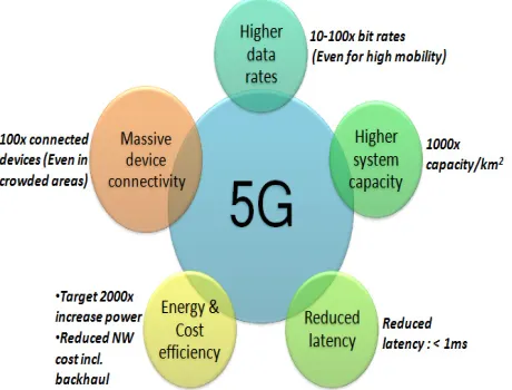
One of major objectives of 5G services is to supply ultra-high capacity per terminal, improve spectrum efficiency. Along with the development of autonomous networks and manufacturing industries, the use case characteristics and corresponding access requirements [1] (See Fig.1) for increment capacity will be exponential growth. In the next 10 years, mobile broadband applications will drive demand for higher traffic capacity and faster data rates in the wireless access network. Meanwhile, future wireless networks should supply lower cost and more efficient power saving to carry the massive traffic affordably and sustainably. The provisioning of faster mobile data rates, we envision data rates on 10 Gb/s for specific scenarios, such as indoor offices
and university campuses. To guarantee support for latency-critical
machine-type-communication [2] (MTC) applications, 5 G wireless access is expected to control latency on 1 ms or less. From the massive MTC connectivity perspective, 5 G must enable the availability of low cost devices and sensors. Future wireless devices should operate with extremely low energy consumption. To fulfill long-term traffic demands, 5 G is promising to expand the transmission bandwidth for multi-Gb/s data rates. 5 G millimeter-wave [mmW] range refers to the frequency range of operation from 10 GHz up to 70 GHz or even higher. Ultra-lean design is essential for wireless access in high frequency bands.
1Dr. Dan Ye, Prof. Lin-shan Lee and Prof. Kwang-Cheng Chen are with the Department of
Figure 1. 5 G wireless access requirements.
The reminder of chapter is organized as follows. Section 2 describes a comprehensive overview of current key technical solutions for 5 G systems. Section 3 depicts the network layer, MAC protocol, and physical layer of 5G cellular networks towards energy efficient, low latency and high reliable communication network. Section 4 proposes a novel dynamic distributed maximal scheduling algorithm for augmenting 5G system capacity. Simulation results on throughput and capacity are presented in section 5. Finally, conclusions are reiterated in section 6.
1. STATE-OF-ARTTECHNICALSOLUTIONS
1.1Massive beamforming and MIMO
Advanced antennas with multiple antenna elements are able to improve coverage for high data rate communication and enhance overall system capacity. Beamforming can improve data rates and capacity. Spatial multiplexing can supply multiple data streams simultaneously to one or more terminals. Dense network deployment operating in high-frequency bands can tackle the challenging propagation conditions. Massive MIMO can reduce RF imperfections and control interference distribution.
1.2Spectrum flexibility
Unlicensed spectrum can be utilized to improve capacity, preferably in marriage of licensed spectrum for controlling critical signaling and tackling with mobility. Licensed–shared access is one significant paradigm of spectrum flexibility, where 5G occupied additional wireless spectrum otherwise reserved for other usages.
1.3Low latency
Reducing transmission time intervals and increasing the bandwidth of radio resource blocks can achieve lower latency over radio link. This could be complemented by fast decoding at the receiver to reduce processing delay in physical channel structure. This can be realized by enabling instant-access resource allocations to alleviate collision. Since low-latency communication between devices is in close proximity, a direct device-to-device communication link can assist low-latency transmission.
1.4Convergence of access and backhaul
In 5G cellular networks, convergence of access and wireless backhaul links will appear and the overall network design will be in combination with them. Wireless connectivity between radio network nodes should simplify the dense deployment with its large number of nodes. Deploying optical fiber at higher frequency bands with larger amounts of spectrum in combination with massive beamforming and low-latency transmissions should be taken into consideration. Spectrum resources are utilized more efficiently by using the same radio interface technology for wireless access and backhaul links. Same operational and maintenance systems are able to be transplanted for both links.
1.5Enablers for massive MTC
Devices with lightweight radio module design and communication modes can operate for years on tiny batteries. “Zero-overhead” communication is achievable by simplifying connectivity states for terminals and supporting channel access with minimal signaling overhead. Maximizing the devices’ sleep opportunities can minimize power consumption, resulting in long battery life. Massive machine-type communication will operate below 3 GHz and even below 1GHz. “Spectrum compatible” interface will provide best coexistence with cognitive radio technology. The evolved 5G networks could enable service to reduce energy consumption for MTC devices by longer sleep cycles and seamless connectivity enablers with reduced overhead, or provide higher reliability for mission-critical MTC.
2. NEWPARADIGMIN 5G CELLULARNETWORKS: FULL DUPLEX COGNITIVE RADIO WITH ENERGY-EFFICIENT, LOW-LATENCY AND HIGH-RELIABILITY
significant fundamental technology in 5 G Physical layer is Sparse Code Multiple Access (SCMA) [4], which could adapt the frame structure by virtue of MAC payload. SCMA was proposed to accommodate complex entries in the signature matrix and each transmitter takes a different codebook to avoid the coupling, which was considered as an energy efficient uplink approach for future 5 G wireless systems. Other transmission technologies such as frequency domain (millimeter wave [5], [6]) or spatial domain (massive MIMO technology [7] or ultra-dense network deployment) are to increase the radio resources.
Cognitive radio network (CRN) [8] is considered to be one of key promising components for next generation mobile network. Interference-tolerant CRN reaps the benefit of enhancing spectrum utilization by opportunistically sharing radio spectrum resources with licensed users, as well as better spectral and energy efficiency. 5G cellular network is developed towards lower latency, higher energy-efficient [9], higher reliable, higher mobility communication network. Uplink and downlink base station communication, cluster network management, overlay and underlay spectrum sharing, management pricing, hybrid access mode, machine to machine communication [2], all contribute to 5 G cellular network architecture with more flexibility, smart coverage (adopt dynamic beamforming technology). Satellite communication can guarantee integration of geosynchronous orbit (GEO) and low Earth orbit (LEO). Content distribution network (CDN), service integrating, and 3D network service-driven coverage are consisting of alternative solutions for improving network performance. IoT becomes more and more important technology as an application challenge for future 5 G communication.
With future deployment of Full duplex (FD) [10] systems, time division duplex (TDD) and frequency division duplex (FDD) will be harmoniously integrated, enabling all the half duplex mobile phone operations for superior 5 G performance. Full duplex is expected to maximize to double spectral efficiency by transmitting and receiving signals at the same time and frequency. Besides, the envision of 5 G is a heterogeneous network (HetNet) where FD operates efficiently at enhanced small cell, wireless backhaul, relay, ad hoc and mesh network. Therefore, full duplex cognitive radio in combination with MIMO is an innovative candidate for enhancing spectrum usage.
3.NOVEL DYNAMIC DISTRIBUTED MAXIMAL SCHEDULING ALGORITHM FOR 5G CELLULAR NETWORK
communication to fulfill these significant performance requirements. This chapter proposes a novel dynamic distributed maximal scheduling algorithm for future 5 G systems.
3.1Tuple-based Distributed Maximal Scheduling
3.1.1Tuple-based cognitive network model
Given cognitive radio network with node set and link set . Each node
has radio interfaces. There are channels available. The tuple (n, mn, c)
represents the mn th radio of node n is operated on channel c. Assuming that the
tuple-based cognitive network model includes primary user node i and secondary user node j. Two tuples p and p’ form a tuple link if they are on the same channel. n(p) denotes the node n generating the tuple p. Thus, the nodes n(p) and n(p’) form an link
in . Tuple links of primary user node and secondary user node can be denoted as (i,
mi, c) and (j, mj, c) respectively .
Considering CR network is MR-MC network, a packet enters and leaves a node through different radio-channel combinations. Tuple-based cognitive network refers as a packet can enter and leave a cognitive radio node via different tuples through in-node transitions.
3.1.2Interference Model for Gaussian cognitive interference channel (G-CIFC) with Tuple Links
Assuming there are two tuple links: Primary user tuple link (p1,p2) and Secondary
user tuple link (p3,p4) interfering with each other according to two types of conflict. • Radio conflict: p1and p3, p1 and p4, p2and p3, p2 and p4, shares a common radio
interface.
• Co-channel interference conflict: The original links l(p1,p2) and l(p3,p4) are within
each other’s interference range, and c(p1,p2)= c(p3,p4). That is to say, primary user and
secondary user occupy same channel to transmit.
Define as the set of tuple links that conflict with the tuple link and set
. Interference degree over the set is the network interference degree
over the whole tuple network. If the ratio between the interference range and communication range is K, the interference model can be termed as K-hop
interference model. The interference degree is defined as the maximum number
of links in that do not interfere with each other, when they operate on the same
channel. The interference degree K of the whole network is the maximum interference degree over all links.
G Ν L n∈ Ν
n
M C
G
0< <i N,0< <j N
( )
I l l
( )
l∈I l y l( ) I l( ) y
( ) K l
3.1.3Optimal capacity region
Let denote the outcome of the scheduling algorithm at time-slot t,
where is the set of noninterfering links that are chosen to transmit on channel c
at time t in MR-MC wireless network. Let denote the number of packets that
link l can serve at time-slot t. . Let and denote the queue
length at the transmitter node and the receiver node of link , respectively.
The optimal capacity region can be obtained by maximizing the sum of
queue-weighted link capacity as below
(1)
(2)
where the backlog or queue length of link at time can be obtained by
. (3)
Throughput-optimal control can be calculated as below: select flow at each link
as , then use as link weight to calculate the
throughput-optimal scheduling.
Let denote the vector of link flow rate loaded to 5G networks.
The optimal capacity region can be calculated as the supremum of the capacity regions of all algorithms. DDMS algorithm is designed as a throughput-optimal algorithm to compute the optimal capacity region . The capacity efficiency ratio of a
suboptimal scheduling algorithm is the largest number such that DDMS can stabilize
the network with any load .
4.2 Tuple-based Throughput-Optimal Control
Consider F data flows over 5G networks with input rate vector
.
Let denote a tuple associated with a source node s, and Let denote the
input rate of flow f from source tuple . Let represent the in-node transition rate
( ) { c( )}
M t = M t
( ) c
M t
( ) l
D t
Dl(t)= wlc
c:l∈Mc(t)
∑
Qb l( ) Qe( )l( )
b l e l( ) l
* ( )
M t
*
( ) : ( )
( ) argmax l( ) l( )
M t l l M t
M t Q t D t
∈
=
∑
( ) ( , ): ( )
argmax ( ) w
c c
c
l l
M t l c l M t
Q t
∈
=
∑
l t
( ) e( )
( ) ( ) ( )
l b l l
Q t =Q t −Q t
*
f
l f*=
arg maxf{Qbf(l)
(t)−Qef(l)
(t)} f* l
Q
Ω
Ω
γ
s
p
ps f
λ
s
of flow f from p to p’, within the node n(p)=n(p’). The flow allocation over each tuple
link for each data flow f denoted as to maximize the total utility over the
network. The utility function of each data flow is .
Joint resource allocation problem can be formulated:
(4) Subject to: (5) (6) (7) (8)
where are the vectors for optimization variables of input flow rates,
input flow rates over source tuples, flow allocation over tuple links, and in-node flow transition rates, respectively.
4.3Cross-Layer Control With Best Path Selection
Decomposable cross-layer control can mitigate the end-to-end delay by integrating a network layer path selection with the link layer scheduling.
is the number of paths from source to destination for flow f, and is the
number of hops for path k, where . Let denote routing matrix
and represent the faction of flow f injected to path k.
Given the input rate , the minimal latency can be formulated as below:
(9) Subject to: (p,p') or f f l r r
( f)
U λ
(p',p) ', (p,p'')
':(p',p) Lp ': ( ') ( ) '':( , '') p
f f f
p p
p p n p n p p p p L
r µ r
∈ = ∈ + ≤
∑
∑
∑
, '' '': ( '') ( ) , { } fp p s
p n p n p
f F p p
µ
=
+
∑
∀ ∈ ∀ ∉(p',p ) ', (p ,p'')
':(p',p ) L ': ( ') ( ) '':( , '')
s s s s
s p s s p
f f f f
p p p
p p n p n p p p p L
r µ λ r
∈ = ∈ + + ≤
∑
∑
∑
, '' '': ( '') ( ) , : ( ) ( ) s s fp p s s
p n p n p
f F p n p s f
µ
=
+
∑
∀ ∈ ∀ =( , '')
', '':( , '') ( , '')
': ( ') n(p)
max
p
f c p p
p p p p p L p p
p n p f
w
µ
∈ = ≤∑ ∑
µ
pf,p'≥0
f
∑
∀f ∈F,∀p and p' with n(p)=n(p') (p,p')f 0 , ( , ') L pr ≥ ∀ ∈f F ∀ p p ∈
( )
R f Hk
{1,..., ( )}
k∈ R f [ϒkpf ]
f k
A
( )
A , 1
m in A
f k
R f
f
k k
r f k
H
=
Λ
∑ ∑
(10)
(11)
where is a positive control constant.
The Lagrange multipliers algorithm can solve the optimization problem in (4) and (9).
(12)
(13)
A joint routing and maximal scheduling algorithm is described as follows.
At time-slot t, for flow f, the input traffic is injected into the path , the
best path selection can be obtained by
(14)
can be regarded as the end-to-end delay, where affects the
end-to-end transmission delay and indicates the total queuing delay along
path k.
Tuple-based back pressure algorithm is defined as
(15)
(16)
where is the backlog of flow over a tuple link (p,p’).
denotes all the maximal scheduling sets over the tuple-based network. The control
parameter is to tradeoff the impact of transmission delay and queuing delay on path
selection.
Then, apply (16) to schedule the parallel transmissions in the distributed fashion.
4.4Local-Pooling Factor Analysis
A capacity efficiency ratio of the tuple-based GMS algorithm can be achieved by
. The -dominance can significantly determine the capacity efficiency
ratio of the GMS. The capacity efficiency ratio of tuple-based GMS under a
Akf k=1
R(f)
∑
ϒkpf+ r(p',p)f
p':(p',p)∈Lp
∑
≤ r(p,p'')fp'':(p,p''∈Lp)
∑
r(p,p')f ≥0 ∀f ∈F,∀(p,p')∈Lp
Λ
( )
1
( ) min{ ( H )}
f k
R f
f f f
k k p kp
A f k p
L Q A Q
=
=
∑ ∑
Λ +∑
ϒf
λ
*( )
k f
*
1 ( )
( ) arg min{ Hk pf( ) kpf}
k R f p
k f Q t
≤ ≤
= Λ +
∑
ϒH f f
k p kp
p
Q
Λ +
∑
ϒ Hkf f p kp p Q ϒ
∑
* * * ' ( , ') (p,p') Lmax{ [ ] r }
P
f f f
p p p p
r Q Q
+ ∈ −
∑
* ( , ')(p,p') ( , ')
( , ')
max{ (t) w }
P
P
f c p p
p p M
p p L
Q
∈
=
∑
* * *
(p,p')(t) [ ']
f f f
p p
Q = Q −Q + *
f MP
Λ
1 1
2
y ≥ K+ σ
(GP)
given network graph is equal to its local pooling factor . A lower
bound of capacity efficiency ratio of the tuple-based GSM is
, (17)
where interference degree denotes as the maximum number of links in that
can be scheduled at the same time without interfering with each other. Similarly, the tuple-based maximal scheduling can achieve a capacity efficiency ratio of
. (18)
4.5Dynamic Distributed Maximal Scheduling
Adaptive flow control: Adjust queue length at the source node of flow f to
achieve maximal throughput scheduling, maximal data rates scheduling. Thus,
dynamic distributed maximal scheduling adjusts backlog at flow- queue over
link according to values obtained by computing maximal throughput and
maximal data rates , maximal link capacity region . This scheduling is the
combination of Back-pressure-based scheduling and Longest-queue-first scheduling.
Meanwhile, DDMS optimizes the largest number to compute capacity efficiency
ratio to obtain optimal capacity region. Furthermore, apply automatic cross-layer traffic control to achieve maximal throughput and link capacity. The multicast scheme can update scheduling message to maintain maximal capacity. The detailed procedure is shown in Table 1.
Table 1. Dynamic Distributed Maximal Scheduling Algorithm Step 1: Automatic multi-mode switch.
Initialization: switch to “zero-overhead” mode for energy efficiency. //Minimize energy consumption and minimize network signaling overhead
Step 2: Compute throughput by maximalinput rate of flow f via (13).
Step 3: Compute capacity efficiency ratio by local-pooling factor via (17).
Step 4: Dynamically adjust backlog via (16) by computing maximal throughput
and maximal data rates , maximal link capacity region .
Step 5: Automatic cross-layer traffic control.
Adaptive flow control: Adjust queue length .
( , , )
P P P
G P L I σ*P( )G
* 1
2 P
d σ ≥
+
( ) L
d l I lL( )
1 1
2
y ≥ K+
f
q
*
f l
Q f
l ( f)
U λ
(p,p')
f
r M t*( )
γ
( f)
U λ
*( )
M t
*
f l
Q
*( f)
U λ *
(p,p')
f
r MP*( )t
f
Collect queue length to calculate the end-to-end delay: a scheduling update message broadcast from a source node includes accumulated queue lengths over all the hops. When destination node receives this message, it will add its local queue length accumulated to the queue length of destination node. The destination node further multicast its updated accumulated queue length in its scheduling update message.
Step 6: Minimize end-to-end delay by integrating a network layer path selection
via (14) with the link layer scheduling via (15) in distributed fashion. // Minimize latency
Step 7: Minimize network interference by (18).
Simulation Result
Construct 23 wireless nodes deployed in a 5G cellular network. The
[image:10.612.202.415.353.499.2]transmission range and interference range of each node is configured as 900 m and 90m, respectively. Thus, K=10. Peak data rate is 10 Gbps, minimal data rate is 100 Mbps. Latency is less than 1 ms. 5G adopted full duplex cognitive radio transmitting signal at 60 GHz. Source node has 20 packets transmitted.
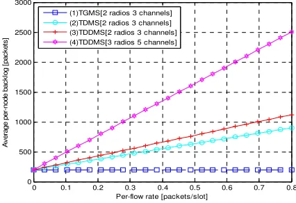
Figure 2. Average backlog with single-hop traffic under different scheduling algorithms using different radios and channels.
Figure 3. Average backlog with six hops traffic under the cross-layer control algorithms using different radios and channels.
* ( ) k f ( ) y l 2
900 900 × m
0 0.1 0.2 0.3 0.4 0.5 0.6 0.7 0.8
0 500 1000 1500 2000 2500 3000
Per-flow rate [packets/slot]
A v e ra g e p e r-n o d e b a c k lo g [ p a c k e ts ]
(1)TGMS[2 radios 3 channels] (2)TDMS[2 radios 3 channels] (3)TDDMS[2 radios 3 channels] (4)TDDMS[3 radios 5 channels]
0 0.1 0.2 0.3 0.4 0.5 0.6 0.7 0.8
0 0.5 1 1.5 2 2.5 3 3.5x 10
4
Per-flow rate [packets/slot]
A v e ra g e p e r-n o d e b a c k lo g [ p a c k e ts ]
[image:10.612.205.413.536.680.2]Compared with the tuple-based greedy maximal scheduling (TGMS) and the tuple-based distributed maximal scheduling (TDMS), the proposed tuple-based dynamic distributed maximal scheduling (TDDMS) can achieve better performance. Randomly pick 23 directed links to deploy single-hop flows. Assuming that the input rate of each flow is the same.
Fig.2 elaborates the average backlog versus the input rate with different number of radios and channels. When the input rate augments, the average queue length soars considerably. It indicates the capacity region of TDDMS. Clearly, TDDMS achieves a larger capacity region than others. The more radios and more channels, the larger capacity region can be obtained.
Fig.3 delineates the average backlog with six hops flows under cross-layer control algorithm. Several scenarios can categorize as TDDMS in single-path (TDDMS-SP), TDDMS in multiple-path (TDDMS-MP), and in the cross-layer control (TDDMS-CLC) under different radios and channels. Fig.3 illustrates that the TDDMS-MP has a larger capacity region than TDDMS-SP, and TDDMS-CLC has an obvious larger capacity region than TDDMS-MP. The better performance of TDDMS-CLC is due to better delay performance on average within larger capacity region.
CONCLUSION
This chapter summarizes the current state-of-art technical solutions for 5 G communication. The key contribution is to innovate a full duplex cognitive radio for the improvement of future 5 G spectrum usage. Another salient contribution is to develop a novel optimal scheduler for maximal link capacity region. The tuple-based dynamic distributed maximal scheduling algorithm is proposed for 5 G cellular network. It combines joint resource allocation with cross-layer control to adaptively adjust backlog and queue length to maximize overall performance. Simulation demonstrates the proposed TDDMS has superior performance.
REFERENCES
[1].Erik Dahlman et al., "5G Wireless Access: Requirements and Realization," IEEE Commun.Mag.,
vol. 52, no. 12, Dec. 2014, pp. 42-47.
[2].M. Zubair Shafiq, Lusheng Ji, Alex X. Liu, Jeffrey Pang, and Jia Wang, “Large-Scale Measurement
and Characterization of Cellualr Machine-to-Machine Traffic”, IEEE/ACM Trans. Netw., vol. 21, no. 6,
Dec. 2013, pp. 1960-1973.
[3].Shunqing Zhang, Xiuqiang Xu, Yiqun Wu and Lei Lu, "5G: Towards Energy-Efficient,
Low-Latency and High-Reliable Communications Networks," ICCS, 2014, pp. 197-201.
[4].Shunqing Zhang, Xiuqiang Xu, Lei Lu, Yiqun Wu,Gaoning He, and Yan Chen, “Sparse Code
Multiple Access: An Energy Efficient Uplink Approach for 5 G wireless Systems,”Globecom2014,
Wireless Networking Symposium, pp. 4782-4787.
λ
[5].Peng Wang, Yonghui Li, Lingyang Song, and Branka Vucetic, “Multi-Gigabit Millimeter Wave
Wireless Communications for 5G: From Fixed Access to Cellular Networks,” IEEE Commun. Mag.,
vol. 53, no. 1, Jan. 2015, pp. 168-178.
[6].Lili Wei, Rose Qingyang Hu, Yi Qian, Geng Wu, "Key Elements to Enable Millimeter Wave
Communications for 5G Wireless Systems," IEEE Wireless Commun.,vol. 21, no. 6, Dec. 2014, pp.
136-143.
[7].Jeffrey G. Andrews et al., “What Will 5G Be?” IEEE Journal on Selected Areas in
Communications, vol. 32, no. 6, Jun. 2014, pp. 1065-1082.
[8].Cheng-Xiang Wang et al., “Cellular Architecture and Key Technologies for 5G Wireless
Communication Networks,” IEEE Commun. Mag., vol. 52, no. 2, Feb. 2014, pp. 122-130.
[9].Qingyang Hu and Yi Qian, “An Energy Efficientand Spectrum Efficient Wireless Heterogeneous
Network Framework for 5G Systems,” IEEE Commun. Mag., vol. 52, no. 5, May 2014, pp. 94-101.
[10].Shuangfeng Han, Chih-Lin I, Zhikun Xu, Chengkang Pan, Zhengang Pan, “Full Duplex: Coming
into Reality in 2020?” Globecom 2014, Wireless Networking Symposium, pp. 4776-4781.
[11].Yu Cheng et al., “A Systematic Study of Maximal Scheduling Algorithms in Multiradio