Editorial
Jane C. Blake, Matugin�; Editor Kathleen ,vi. Stetson, Editor Helen L. Patterson, Editor
Circulation
Catherine M. Phillips, Manager Kristine M. Lowe, Administrator
Production
Christa W. Jessico, Production Editor Elit.aberh McGrail, Tvpographer
Pctct· R. Woodbury, Illustrator
Advisory Board
Samuel H. Fuller, Chairman Scott E. Cutler
Thomas F Gannon Donald Z. Harbert William t\. bing Richard F. Lary Alan G. Nemeth Robcn M. Supnik
Cover Design
Recent advances in physical technology have signiticanrly impmved the capabilities of parallel SCSI in three parameters: speed, interconnect density, and contiguration expansion (device count, length, topology, control). On the cover, the graphs reprc· sent three systems with different sets of parameter values, rhar is, three unique points in the spced-sizc-contiguration space. Hot plugging of devices and bus segments and dynamic speed changes can
decrease or increase the p;1tamercr values without system disruption. The opening paper in this issue ckscribes these advances in parallel SCSI technology.
The cover design is by Lucind;t O'Neill of the DIGITAL Industrial and Graphic Design (;roup. The editors ti1Jnk .1uthor· Bill H,,m for his help in developing the cover concept.
The LJ(�ita/ Techllical.fourna/ is a rete reed journ.tl published quarrerlv bv Digital
Equipment Corporation, 50 Nagog Park, AK02-3/IB, Acton, MA 01720-9843. Hard-cop'' subscriptions can be ordered bv sending a check in U.S. funds (made pavabk to Digit;11 Equipment Corporation) to the publishcd-bv address. General subscription tJtcs are $40.00 (non-U.S. $60) for four i>'ucs and $75.00 (non· U.S. S liS) for eight issues. Uni,-ersirv <tnd college prokssors and Ph.D. sn1dents in the elecuical engineering and com puter science fields rccei,·c complimenran· sub· sniptium upon request. DIGITAL customers may qualif\· tor gili: subscriptions and are encour· aged to conracr their account represenratiH�S. Electronic subscriptions are a\·ailabk at no clurgc bv accessing U RL
http://www.digital.com/info/subscription. This service will send an electronic mail notiticc1tion when a new issue is available on the Internet.
Single copies and back issues can be ordered bv sending the requested issue's volume and number and a check tor $16.00 (non-U.S. $18) each to rJ1e published-by address. Recent issues arc also available on the Internet at http://www.digital.com/info/dtj.
DIGITAL employees may order subscrip· tions through Readers Choice <H U.IU, http://webrc.das.dec.corn.
Inquiries, address changes, and compli
mentary subscription orders can be sent to rhc Digital Technical.fournal at the published-by address or the electronic mail address, [email protected]. fnquiries
can also be made by calling the Journal office at 978-264-7556.
Comments on the content of anv paper and requests ro (Onracr Juthors .1re welcomed
.md mav be sent to the managing editor at the published-bv or electronic mail address. Copyright 1998 Digital Equipment
Corpor;uion. Cop,·ing without tee is per mined provided tlur such copies .tre made for use in educational instimtions b,· facult\· members and arc nor distributed for com mercial ad,·antage. Abstracting with credit of Digital Equipment Corporation's author ship is permitted.
The information in the.fourna/is subject ro ch;�ngc without notice and should not be construed as a commitment bv Digital Equipment Corporation or by the corn pan· ies herein represented. Digital Equipment Corporation assumes no responsibility for anv errors that rnav appear in the Journal. fSSN 0898-901X
Document;ttion Number EC-P8826-20
Book production was done b)' Quantic
Communications, Inc.
The f(JIIowing arc trademarks of Digital
Equipment Corporation: AlphaScn·er, AJphaStation, Cl. DC:Cnct, DECNfS, DIGITAL, the DIGITAL logo, DIGITAl. UNIX, and PowcrSrorm.
fkum.n is ,1 rr.Hkm.1rk ot"Son�· Corpor.nion. CRAY is .1 regrstcrcd tro1eicmark of Crow Research, lnc.
Dircct3D is a rradcm;ukof31)bbs, lnc.l.td. Microsoli:, Visual C++, Windows, \Vindo"·s 95, and \Vindows l'\T .nc n.:gi�rtrt:d rr.H.kllLlrks and Neti\lcering is J rr.tdemark of J\'(icrosor·r Corporation.
Nctscapc Communicaror is :1 rr:hkm.trk or· !\lcrscape Communications Corporation. Pro/E'\GI'\ELR is a registered trademark of Par.1mctric Tcchtl<)lot,�· Corporario11. Total View is a trademark of Dolphin
Interconnect Systems, Jnc.
UNIX is a registered tradcm;uk in the United States and other counrries,liccnscd I.:'X(lusivdy through X/Opcn Company l.td.
Contents
Foreword
Recent Advances in Basic Physical Technology for Parallel SCSI: UltraSCSI, Expanders, Interconnect, and Hot Plugging
Development of Router Clusters to Provide Fast Failover in IP Networks
Shared Desktop: A Collaborative Tool for Sharing 3-D Applications among Different Window Systems
Challenges in Designing an HPF Debugger
Richard Lary 3
William E. Ham 6
Peter L. Higginson and Michael C. Shand 32
Lawrence G. Palmer and Ricky S. Palmer 42
David C. P. LaFrance-Linden 50
2
Editor's
Introduction
This issue of tile Digital Technical
journal presents papers on a range
of computing subjects, beginning with recent advances in storage tech nologies, foUowed by net\vork routcr cluster enhancements, new desktop software for sharing 3-D applications across platforms, and an experimental High Performance Fortran debugger.DIGITAL's storage engineers have been leaders in the definition of the parallel small computer system inter face (SCSI) ANSI standards and in related technology improvements. Bill Ham's paper focuses on four advances in the physical features of SCSI that resulted in major increases in SCSI capabilities and minor distur bances when incorporated in existing installations. The discussion spans developments from SCSI-2 through UltraSCSI, including speed increases in the synchronous data phase; longer, more complex configurations enabled by bus expanders; physical versatility inherent in a decreased size ofthe interconnect; and dynamic removal and replacement of devices on an active bus (hot plugging).
The subject of our next paper is networks, and the emphasis of the engineering is on customer require ments for reliability and availability. Router clusters, described here by Peter Higginson and Mike Shand, were developed to provide tast fail over response in lP net\vorks and are defined as a group of routers on the same local area net\vork (LAN) pro viding mutual backup. New router cluster protocols and mechanisms restrict the loss of service that results from a failure on the net\vork,
speci-Digital Technical Journal
ficaiJy on net\vorks requiring high availability, such as telecommunica tion and stock exchange net\vorks. The authors analyze failure cases and present the solutions that reduced service-loss rime from approximately 30 to 45 seconds to 5 seconds in both LAN and WA.l'\1 environments.
Collaboration software for desk top systems can be broadly defined to encompass a range of capabilities, fi:om a simple transfer of data between users, such as e-mail sent over a net work, to real-time sharing ofrext, graphics, and audio and video data. Larry and Ricky Palmer have designed a sofhvare product, called Shared Desktop, for users who want to share three-dimensional graphics applica tions and audio across net\vorks. Notably, the design differentiates itself by supporting mulriple operat ing systems, currentJy enabling real time interopcration among vVindows and UNfX systems. The authors dis cuss the decision to create a "view port;' which is a part of the desktop screen, and issues they addressed dur ing implementation, including proto col splitting, screen capture and data handling, and dissimilar fi·an1e bufters. They conclude with ideas for possible enJ1ancemcnt of the product in the future.
In a previous issue of
tl1ejoumal
featuring technical computing topics (vol. 7 no. 3), Jonathan Harris et al. described DIGJTAL's Fortran 90 compiler that implements High Performance Fortran version 1.1, a language tor writing parallel pro grams. An outgrowth of that work is an experimental debugger,code-Vol. 9 No.3 1997
named Aardvark, tJ1at "reconstructs" for the HPF programmer a single source-level view, even though the program has several flows ofconu-ol and the data are distributed. David LaFrance- Linden discusses the chal lenges faced in creating the debugger and describes useful techniques and concepts, such as logical entities, that can be generally applied to debugger design.
Readers interested in past issues of the]ouma/are invited to visit the jou.rna!Web site at http:/ /vvww.
digital.com/info/dtj/. Our next issue will address such topics as opti mization of NT executables on Alpha, a new graphics program, and VLM. A Special Issue on programming lan guages and tools is being developed for publication in the fall ofl998.
Foreword
Richard Lary
DIGITAL Storage Technical Director
Welcome to the winter 1997-98 issue of the
Digital Technicaljoumal.
This issue does not have a single theme;it contains a potpourri of papers on
a wide range of technical topics. This provides the toreword writer with a small gift and a not-so-smaiJ headache.
The gift is the opportunity to tout the continuing fecundity of DIGITAL's engineering community. All the papers in this issue of the
journal
come from product development groups in DIGITAL, and all the tech nology described herein is directly applicable to the problems of using computers in the real world. The papers themselves cover a wide range of topics: designing storage buses and their infrastructure; buiJding tP routers that reduce network delays caused by link or router failure; sharing 3-D graphical and audio data across networks of computers with different windowing systems; and debugging programs written in languages tJ1at incorporate data parallelism.The headache, of course, stems from this very diversity. Any attempt to derive some set of common under lying principles other than "make better stuff" from this collection is doomed to sophistry. And my techni cal background is too narrow to pro vide any significant embellishment to any of the papers outside the domain of storage systems. So, with apologies to the otJ1er autJ1ors, I am forced to restrict my comments to what I know -tJ1e background and impact of Bill Ham's work on advances in parallel
SCSI which are presented in his paper in this journal.
Bill Ham's paper not only describes a significant technical achievement; it illustrates DIGITAL's shift from
engi-neering proptietary storage systems to engineering open storage systems.
The SCSI bus was developed dur ing the early 1980s as one of many attempts to standarcLze the interface to storage devices. It succeeded beyond me expectations of its developers, largely because it supported a device model tJut was abstract enough to be extensible but inexpensive enough to be implemented in the technology of tJ1e time. For all its advantages, how ever, SCSI suffered from poor engi neering at the physical level. This was a direct result of the way it was devel oped. The diverse corporate repre sentatives that defined SCSI did not have the time or money to specif)' and build cuswm bus infi·astructure com ponents (transceivers, cables, termi nators, etc.), so they used commonJy available parts. A lack of sophistica tion in specifYing physicaJ interface parameters resulted in a specification tJ1at aJiowed too much component variation. As a result, it was difficult to build reliable, multi-box systems using SCSI.
DIGITAL's attitude towards SCSI
during this period was to ignore it and hope it would go away. We had designed our own proprietary DigitaJ Storage Architecture
(
DSA), which utilized an abstract and extensible device model and also incorporated m<my large system fearmes, including a robust physical interconnect. We controlled the design and manufac ture of all DSA components and could thus guarantee that they all met tight architectural specifications. Moreover, DSA was a key enabling technology for VMS Clusters, the individual DSA components were competitive wirh their counterparts4
t!·om rhc proprier:trv sror:tge architec tures oforher brge SI'Stcms compa nies, our customers wnc haplw, �111d
the storage business was prollt:tble. We were reeling quire pleased with ourselw -and we were prot{JLmdlv ignorant ofrhe power of:t successful open marker sr:mchrd, since one had never existed in the sror:tge world.
During the l�mer lulfofthe 1980s, SCSI grew steadily in popubriry until
ir domin:trcd rhc workst:trion and small-server nurkcrs. These svstcms had at most�� kw disk drives on them, and SCSI's signal integrity problems were mJ.nage:�ble in th:tr context. Thev II'CIT nor m;1nageabk in rhc larger and more demanding data center SI'Stems, and so SCSI 11·as nor used there. The SCSI standards group ,,·:-�s ;111·are ofrhe bus's deficien
cies, holl'cvcr, :tnd as the decade pro
gressed, the group made amendments ro the srand;Hd ro elimin�ue man1· of
them. Bv the turn ofrhe decade, sc1 -er::d independent subsystem n:ndors were selling subsystems utilizing SC:Sl de1·ices ;1S storage t(lr large J)!C!TAL svsrcms. These subsystems did not, in general, h�11·e the te:Jtures, pert{Jr-11Jancc, or robustness of our su bws rerns, bur they were signillc:�nrlv cheaper and improving �11! the rime. By 1991, ir had become obvious ro us rh:tr we would nor be able to com perc with these systems in rhe long run. They were leveraging an entire indusrrv's investment and talent :md were reaping rhe cost hcndirs of high-volume manubcnn·ing; whereas we had to design and nunuhcrurc (�1r rclarivclv low volume) cverv component of even· DSA svsrcm oursell'l:s.
Our position ll'as untenable. vVe had to ch:�.ngc our strategv and embrace the bus rlut ,,.c had so srudiousil' ignored.
We designed a modular packaging :�rchirecture tor SCSI de�·ices (known wmmerciallv as Storage Works) �md :1 ser of storage arrav conu·ollcrs thar
inrcrbccd these de1'ices to our svs tcms (and systems t!·om or her major
vendors as well). We :�lso became active participants in rhe SCSI stan (brds process. Where DIC!TAL h�1d prn·iouslv sent one or rwo engineers
to SCSI standards meetings snicrly to
gather inh:.>rnution, we starred ro send
up to halfa-dozcn engineers to listen,
learn, p:1rticipare in de bare, help
11·ith the grunt II'Ork of rhe st�lJl(h·ds process, and make propos:ds ro amend or extend the st:mdard in direcrions usdi!l ro us :md our customers.
Our nell' modular pacbging design alloll'cd our customers ro i nsr:1ll and remo1·e storage de1·iccs
rhcmsch·es and ro mig1·�ue sror�1gc dc1·ices ben1·een S\'Stems, e,·en
bct\\'Ccn s1·srems built bv different wstcm 1·endors. This modularity pro1·ed to be a ,·en· l'aluable te:trure ro our customers. Ho11·e,,er, ir required us to build a plll'sic.ll infra structure for the SCSI bus rh:tt had rbe robustness needed Lw our Lnge svsrcms and that could accommodate a great de�11 oh-ariabilirv in contigur:� rion, and to use a bus rhar was known ro have residual sign�11 inregriry prob lems in its physical interconnect. vVc ll'ere undcrstandablv ll'orricd about this, worried enough to charter :t small group of engineers as �l SCSI
Bus Technical Office (SBTO) within tht: sror:tge group, and to dt:1·elop
Vol. 9 No.3 1997
shon-rcrm conllgurarion guidelines tor our packaging �1rchitecture and long-term technical proposJis tor rhe SCSI plll'sic:ll bus architecture. Bill
Bam has been the head ofSBTO since irs inception :md has also been our rcprcscnt:trivc to rhc SCSI corn mince on :1ll matters relating ro the physical bus interconnect.
In the summer of l993, Bill com pleted �1 study ofrhc signJ.I integrity issues surrounding par:tllcl SCSI. His conclusions were startling. The SCSI standards commirrcc lud, over the \'ears, made enough improvements in the b�1sic rr�1nsrnission line char:tcreris rics ofrhc SCSI bus rhar mosr of rhe remaining signal integritY problems ,,.c,-c due ro rhc 1·�1riarions in compo IKnt parameters J.llm\'\:d b1· rhc SCSI
specillurion. Exercising righter con trol m-er componcnr l':lriarion- rhmugh building selected compo nents or through purch:tsc specillc:t
rions ,,·irh our supplicrs-ll'ould nor onh· produce excellent signal integrin· in our packaging bur II'Ould all011' the maximum dock r:�rc of rhc bus ro be doubled ll'hile m�1int:�ining excellent signal inrcgrit\' and b;1Ckll'ards com p�uibilin· with existing SCSI de�·iccs. Bill's results also indiutcd rhar the maximum clock r:1te could be incrc:1scd CI'Cil further, wirh more 1\'0rk,
Tbis discovcrv c�1n1e ar a criric1l rime in rhc evolution of the SCSI
sr�md:trd. 1\!luch of rhc SCSI stambrd com mince's cH(Jrt in the c:-trly p�1rt of the 1990s was being spent in modif\1-ing rhc SCSI sr:�ndard so rhar serial buses could cu-rv rhe higher lcvd
SCSI bus protocols. The committee
assumption rhar parallel SCSI was "our of gas" in pertormance, and
the new serial bus variants would supplant it by mid-decade. However, by 1993 not only was the definition and implementation of the serial bus going slower than expected, but there were rlu·ee independent and incom patible serial bus proposals, each with unique useful features and unique drawbacks, each with a cadre of sup porters among the industry represen
tatives. The marker would ultimately choose which serial buses would thrive; bur it was highly unlikely that all three would thrive. Storage ven dors that made the wrong bus choice would suffer for it. Most gaJJing to the technophiles among us, the mar ket's choice could not be predicted from the technical merits of the con tenders. I f it could, we'd all have Betamax VCRs in our homes today.
So, DIGITAL decided to have Bill present his results to the SCSI com
mittee at its November 1993 meeting
and recommend that the committee extend the SCSI specification to allow the bus to run at up to twice its old
maximum clock rate if the components in the physical interconnect met the tighter specifications. Our motive in doing this was purely selfish: we were not ready to choose among the serial bus proposals, yet we would soon need more performance than parallel
SCSI could offer. A higher perfor
mance parallel SCSI would allow us to improve our storage subsystem
performance without having to stake
our fortunes on a potentia
l
Beta max.Bill's presentation at tbe SCSI committee meeting was met with enthusiastic approvaJ. It turned out surprise!-that other system vendors were tee ling as uneasy as we were about the serial SCSI buses. The pro posal, christened UltraSCSI, was adopted as an extension to the parallel SCSI standard. Bill Ham and the SBTO then worked with component vendors and the SCSI committee to develop the thinner cables, smaller connectors, and SCSI expander cir cuits described in his paper, all with the aim of keeping parallel SCSI as a desirable alternative to the serial SCSI buses. Today, tour years after its
com-mittee debut, UltraSCSI is solidly entrenched in the storage market. In fact, storage market anaJysrs are now projecting that the combined volume of devices on all serial SCSI buses (yes, there are still three, but the market has already picked one, Fibre Channel, as the winner) will nor exceed parallel SCSI device volumes until early in the next century. And the SCSI committee has finished extending the paraJlel SCSI specifi cation to achieve a second doubling of maximum bus clock and is in the midst of defining a third doubling.
Without hyperbole it can be said that the technology embodied in Bill Ham's paper has directly affected the course of the computer storage indus try, and it continues to affect posi tively DIGITAL's position in that industry. Enjoy reading the paper and those that follow it in this issue.
6
Recent Advances in Basic
Physical Technology for
Parallel SCSI: UltraSCSI,
Expanders, Interconnect,
and Hot Plugging
DIGITAL uses SCSI technology in most of its storage prod ucts and conseq uently has led major standards and industry bodies to im prove the technology in the following areas: increased synchronous data phase speed beyond fast SCSI; longer, more complex electrical configurations by means of expander circuits; versatil e and more manageable con nectivity th rough a smal ler, improved physical intercon nect; and dynam ic device i nsertion and removal. Data phase transmission rate extension is achieved through understand ing and controlling silicon chip timing and transmission media parameters. Using expander devices to confine transmission line effects to shorter segments allows large increases in the maximum distance between devices and in the device popu lation withi n the same SCSI domain. Expanders enable complex, hublike configurations to be created without changing existing SCSI devices or software. The use of 0.8-millimeter connector tech nology and consideration of cable losses has reduced the physical size of the external shielded inter connect by approximately two thirds, decreased the number of parts required to support com plex config u rations by a factor of 10, and i ncreased the i nterconnect density to the same l evel used in serial SCSI. Finally, the mating and demating events that occur during device inser tion and removal produce a spectrum of small, undetectable, electrical distu rbances on the active bus that appear to be l i m ited by the physics of the media and device capacitance.
Digirc1l Technic3l Journal Vol. 9 No.3 1997
I
"VtiJiam E. Ham
Introduction
Parallel SmaJJ Computer System Interface (SCSI) is the
workhorse technology tor most of the storage applica
tions in DIGITAL products today. This device and
interconnect technology spans all system offerings
fi-om the simplest to the most complex. SCSI was intro
duced to the higher-end products in the early 1990s as
the open systems follow-on to the DIGITAL propri
etary Digital Storage System Interconnect ( DSSl) and
Computer Interconnect (CI) technologies.
As system demands have increased, SCSI has evolved
to meet the needs. DIGITAL has made considerable
contributions to the technology and led the effort to
achieve industry standardization. This paper details the
most significant developments in the physical features
of parallel SCSI technology over the last several years
th:1.t have allowed it to continue to serve DIGITAL cus
tomers in an eHective, competitive way. The discussion
targets the following four important areas:
l.
Speed increases in the synchronous data phase,
which resulted in the ANSI definition of UltraSCSI
(Fast-20 SCSI) technology!
2. Development of software-invisible circuits, gener
ally called expanders, that enable segmentation of
SCSI domains i nto easily managed pieces
3.
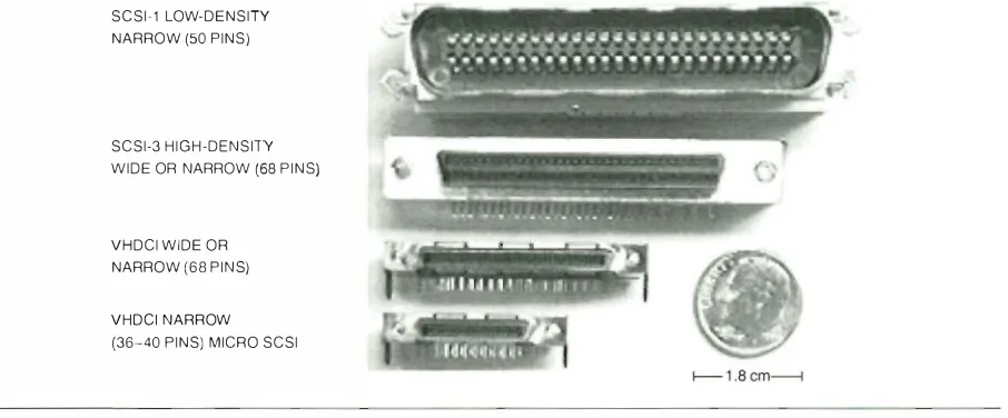
New connector and cable technology, namely the
Very High Density Cabled Interconnect (VHDCJ)
device, that decreases the interconnect size and
complexity by many
told2
4.
Dynamic removal and replacement of devices on an
:.�ctive bus, which is referred to as hot plugging
DIGITAL mad e su bstantial contributions in the
four areas. This work included creating the expander
and interconnect standards projects; leading the work
ing groups that defined the Fast-20, expander, and
interconnect standards; providi n g data for the Fast-20
and hot-plugging projects; and proposing and gaining
approval for the hot-plugging standard.
paper focuses on developments from SCSI-2 through
UltraSCSI and specifically does not address the new
Low VoltJge Difterenrial ( LVD) technology being
introduced tor the high
est-
sp
eed appl ications.
Pedigree
SCSI is defined in several ANSI srandards13' and in the
material that was developed to create these standards.5 "
The standards were generated
over thelast decade
through
acooperative
effort oL:�pproximately60 major
co
mpan
ies in th
e computer and computer support
industry. As a resu lt of this pedigree, d1e prime directive
for SCSI technolot,•y is i nteroperability of devices
designed and manufactured by different companies.
The details of the physical designs used to implement
SCSI may not be visible to users and researchers; these
details contain much of the marketing and technical
differentiation between the prod ucts of the participat
ing companies and are therefore hidden in the silicon
design . The behavior at the device connector pervades
the SCSI specifications. The basic assumption is that as
long as the properties arc compati ble at these connec
tors, device substitution is possible. Thus, SCSI devices
may be both i nteroperable and
ofdifferent designs.
Basic Architecture
This section reviews the basic architectu re of parallel
SCS I . The SCSI bus is
�lparallel, multidrop,
wired-ORcon figuration.
Signal Multi plexing and Phases
The parallel signal
construction of the bus al lows m u ltiplexing of some
signals during different phases of communication so
that the same signal lines mav have \'Crv d i fferent
func
tions in different phases. The physical behavior of sig
nals is usu a l lv l i mited bv the phase during which the
shortest pulses are used and the demands
torsignal
i ntegrity are the highest. The limiting SCSI phase is
the data phase ( pavload phase )
thatis executed with
the highest synchronous rate. For UltraSCSI , this peak
Table 1
Termino logy for Data Phase Speeds
Data Phase Speed Name
Asynch ronous
Slow (synchronous) Fast (synchronous)
Ultra (synchronous)2 U ltra2 (synch ronous)l U ltra3 (synch ronous)'
Maximum Transfer Rate (Million transfers/second)'
Unspecified 5
1 0 20 40 80 to 1 00
repetition rate is 20 m
ega
hert
z( M Hz ) . Table
lcon
tains the genera l ly accepted terminology related to
data phase speeds.
Because of the wired-OR property, each signal in
t he bus m ust be driven
toa known state even i f no
SCSI device is acmal ly d riving the sign : d . SCSI uses the
logical 0 state ( negated state ) as
the undri\·enstate and
uses d1e bus ter
minato
rs to d ri
ve the signal to this statein
the absence of any driving devices. The device signal
d rivers must overcome this terminator-driven logic
state of 0 in order to send a l ogical
l( asserted state )
onto the signal line.
SCSI signals must support all frequencies, ti·om stat
ically dtiven by the terminators onlv ( DC ) to the third
harmonic of the fastest signal edge in the synchronous
data phase. I n many cases, the same wire must support
all these frequencies at different times d uring the SCSI
protocol .
The highest signal edge slew rates tor UltraSCSI
are approximately 500 m i l livolts per nanosecond
( mV /ns
) .
A2 -volt ( V ) transition requires approxi
mately 4 ns/5.4 ns/meter ( m )
=0.74 m tor a signal
edge ( assuming 5 .4 ns/m as the propagation ve locity
of the signal edge ) . Therefore, some relief exists
because the connectors and cable assem bly termina
tions are much smaller than the
sig
nal edge length ; theconnectors
andterminations do not need to have care
fully controlled characteristic
impedance properties.
This al lows the use of the technology available in the
connector and cable assemblv i ndustry to opti mize
the interconnect properties without the considerable
d esign, manufacturing, and test burden imposed by
controlled impedance requirements.
Transmission Modes
The transmission mode or·
aSCSI bus is determined by the properties of d1e
terminators that, by definition, constitute the ends
ofthe bus. Terminators also supply most of the energy
required to operate the single-ended transmission-mode
devices and additionally provide the required matching
Maximum Byte Rate (Narrow) (Mega bytes/ second)
Typically-3
s
1 0 20 40
80 to 1 00
Maximum Byte
Rate (Wide)
( Megabytes/second)
Typica l ly - 6 1 0 20 40 80 1 60 to 200
'One transfer is 1 byte in na rrow mode and 2 bytes i n wide mode; 1 byte equals 8 data bits plus 1 parity bit. 2U ltra is synonymous with U ltra 1 and Fast-20.
3U ltra2 is synonymous with Fast-40.
'Rates not yet final ized; U ltra3 is synonymous with Fast-80 or Fast- 1 00.
[image:9.587.48.514.577.684.2]8
to the characteristic impedance ofrhe tr:msmission l ine. I n differential
S CSI ,
the terminators prm·idc �1 sma l l portion of the mnJII encrf:,'l' required ro opcrnc the bus; the diftercntiJI drivers suppk the rcm�1indcr of the energy.Drivers that wan t to rr:tnsmit an asserted state m ust overcome the biasing pro,·ided L)\' the termina
tors. The d ri\Trs operate loc1i h· on
the bus
�md :1l tert he stare i n their i m mediate ,·ici n i ry \\·hen the\' S\\ i tch on <1n
d
off. For single-e ndedSCSI,
the0
stare isappro
x
im
:1t
el y
2 . 5 V
and the I stJte is <1ppro x i m a re h·0 . 5
V.
For high- ,·oltage d i ftercmialSCS I ,
the 0 stateis approximately -1
V
ro -2V,
:tnd rhc 1 state isappro x i mately
2 V.
( The d i rkr
cncc bct\n:cn <1 state1 and a state 0 i s h igher with d i ff'crentia l-typica l l y, ap proxi mate!\• 4 V. )
Fo
r
single-ended transmissions, the dri\us operate on energy previouslv stored in the bus b\·t
he tnmina tors. This energy is mostly e lectrostatic cncrg\' in the charge stored in the capacitance ofthe trans1uission lineror negated States
:md eJectrOm<1gnetic
CJ1Crf';\' in the current flo\\'ing thr
ough the i n d uctanceof the
trans mission line tor asserted
stat
es. Ultimately, the termina tors will set the state
back to negated Jrtcr the drivers cc
1sc
to source or sink cu rrent; ho\\'cver, this onlv hap pens attcr th
e round-trip prop:tgation d c l:l\' ti·om the dri\·cr to thebrrhcst termi nator
ifthe
busd ocs
not ha\·c matched characteiistic i mpedance propnrics.Approximate ly the same energy transt(mnations occur tor differential
SCSI, but s
ignirie1nr current is supplied bv the d rivers for boththe
asserted and the ncg::tted state s .Multidrop Requirements The multid rop :trch i tccturc req u i res a cominuous lo\1'-rcsistan
ce
p:tth Cli lcd thebus path bet\\'ecn the ter m i nators and �1I I m' s d c1·ic
c
sto
be attached to thi
s pat
h . The n u m ber <1nd propertics of these
a rtJchcd
de\·iccs varv . \l'idclv . because ofmany factors including the speed of opcr<1tion, the overal l length of the bus, and the transmission mod e . Att<1chcd dc\·ices �1 1 \,·a,·s d isturb t h e tL1nsm ission l i ne properties of rhc bus path; the kc\' to successfu l opera tion is in the management of the m agnitude of t hese disturbances.
General ly, the more capacit�mcc or
e
lcc
n·ic1l lengththe dC\·ice has, the rnore disrupri,·c it is . PLlcing-dC\·iccs
roo close together along the bus path c1n cause them
to appear elecrric11ly as a single super disruptive d evice . Pbcing them roo r�u· apart c1n rcsLiit i n an
m crall
bus length that is too long.Wired-OR Glitches During the arbin·,ltion p hase, when the
SCSI
devices decide \\'hich devices \\' i l l besend i ng pavload data to or rrom each other, m u l tiple dC\·iccs mav assert the same
control line ( BSY )
at the s�1mc time . E;JCh dc,·ice that \\'isbcs to commu nicate asserts both theBSY
line and its respective d eviceDig:it,ll Tec hnical )oum,ll \'o l . \! � " · 3 ] 99 7
idcntific1tion ( ! D ) l i n e . A fter exa
m
ining the asserted I D Jines to determine \\'hich dc\·ice has the highest I D,�11 1 but the dn·ice \\'ith the highest
ID
release theBSY
line
. This lc1\ CS onh one device, the \\'inner, assertingthe BSY
l i n e . While the current in theBSY
l ine is readjusting itscl f ri·om a m ulripl
c
- d rivc
r asserted condi tionto a single-d ri\n asserted condition, noise pu l ses
(
called ''ired -O
R glit
che
s)
pr
opagat
e throughout the length ofthe
sig11<1i l ine md J11<1\' be detected col lccti\·ely JS :tn e rroneous p hase.Thcrd()rc,
one of the architecrural limitsf()l'
par<1 i l c lSCSI
isrhc
time requiredtor the
se,,·ired-OR
glitches to settle. This bus settle ri me is set b,·protocol <1t
400
ns and must be interpreted <lS a rou n d trip propaga
t
ion time ,,·hen using a simpleSCSI
bus.Allowing some time f(x propagation through driver :tnd receiver chips viclds a maximum plwsical l
e
ngth tor �1simple
bus of2 5
meters.Areas of Improvement
Thus, the opportunities t(>r improving
SCSI
derive ri·o m appropri<1tc
h' managing the transmission l i nes,t:tking Jlklll tagc
of
the mu l tidrop :trchitccture oHcrcd l)\' o par
a I lei \\ ire
d -0 R structme, using statc-of-the-<1rtt
ec
hnolog
yh-om
the interconnect and silicon ind ustry,�u1d
maki ng i n novative usc of the ti me req uired for the ,,·ire d - O R glitches to settle.These
tec h n iq ues arc the b�1sis oft he de\ clopmcnt lw !)] G lTAJ , in the rour a reb �1ddresscd in this paper.S
peed incrcJscs in
the synchronous cbta phase arc b:tsed pri m :trih· on incrc1si ng the timing pre
cision in the si l icon n·anscci\Trs h,· using nc\\'cr si l icon tec h nolog,·. T h e intercon nect properties rem<1i n largch'
u nch;
m
gcdti·om
those used ror fastSCS I .
Circuits rlut enable segm e ntation
of
S CSI domJins
111 to easi lv m�111ag
e
d pieces are based on svstematic isolation of tLU1smission line pr
operties and usc of\\·i red - O R noise p u l se properties . No
sort\\'are,
interconnect, or devic
e
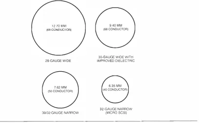
changes needed to usc these circuits. New con nector and c:tblc tcchnol of:,'l' is based on <1n i n no,·,ni,·c 0.8-milli mctcr( m m ) ri hhon-s
t\'lc
con I1ccror tcclmolog\· that optim izes the toLllSCSI clcc
tric11 req u i rements \\'ith the capabilities of cable and connector design .Dvnamic removal and
rcpbcemcnt of
devices on an :tcti,·e bus, i . e . , hot plugging, is based on the multidroparchitecture, '' hich enables d evices to be ;1dd
ed
orrep laced ,,·irhout affecting continuit�· bet\,·cen other d e,·ices. Hor �)l u gging depends on u n d crstJnding and
ll1<1nagi ng the clectric1l d isturbances created during the insertion or t'Cll10\'�11 .
The rcm.1indcr o f this p.1pcr pro\·idcs d etails o f these
t(>ur
arc:ts or' improvement. The end result of these extensions to the basic phvsical architecture of parallelSCSI
is �1 m:tjor i ncrease in i ts capabil ities, accompaI ncreasing the Synchronous Data Phase Speed
Beginning with the SCS I - 2 standard, the synchronous transmission mode is available for transferring payload data between SCSI devices. The devices select this mode by m u tu al agreement before any synchronous data is passed . The agreement is achieved by using the asynchronous transmission mode, which is slow but usualh' reliable.
The synchronous data phase uses the DATA and PARIIT bit lines for the data and either the
REQ
or the ACI<. control l ine as a signal that the receiver uses fc>r capturin g the data. The term synchronous derives fi·om a specified timing relationship between the bit l ine signal edges and theREQ
or ACK signal edges. (The rai l i ng edge of the ACK signal is used when the data phase transmission originates from the SCSI ini ti::Jtor, and the falling edge of theREQ
signal is used when the transmission originates from the target.) There is no synchronous relationship between the internal timing references on different SCSI devices, so the receiver must bufrer the received data before intro ducing the data into its internal data management structure . This bufferi ng is usual l y accomplished by me<ms of a first in nrst out( FI F O )
circuit that uses theR.EQ
or the ACK signal as the latching signal for the incoming data. For convenience, in this paper we only refer to the ACK signal, with the understanding that the same discussion applies to theREQ
signal when it is used as the data-latching signal .Since only the fal ling edge of the ACK signal is used in the presently specified SCSI versions and an ACK sig nal is req uired for every data transfer, it follows that the ACK signal cycles at least twice <1S last as the data bits. When a conti nuous stream of transfers is transmitted , rhe ACK signal is a regularly repeating signal , nomi nally, a square wave . An alternating 1 /0 pattern pro duces the h ighest fimdamental freq ue ncy tor the data bits at half the frequency of the ACK signal. Therefore, the ACK signal requires careful attention since it is the most demanding on the transmission process.
The focus of this section is to examine h ow the speed of rhe synch ronous data phase was increased by a factor of rwo to achieve the Fast-20 ( UitraSCS I ) spccincation.
Status before UltraSCS/
In 1 9 9 3 , the SCSI - 2 standard' had been in p lace rex t\VO years, and a follow-on standard called SCSI -3 Parallel I nterface (SPI)' was technically stable. S P I had been created largelv because the speci ncations in the SCS J -2 standard were not effective in implementing the single-ended \'ersion of the svnchronous transmis sion ( 1 0 megatranskrs per secon d ) . The differential version specined in SCS I - 2 worked well but was much more expensive in cost, power, and space than the
single-ended version. Therefore, most of the interest was in making the fast single-ended version work adequately.
Taking single-ended SCSI from asynchronous and slow synchronous (
5
megatranskrs per second ) to the fast synchronous technology was difncu lt. The prevail ing opinion was that the SPI standard represented the final improvement to paraJJel SCSI . This view set the stage tor a number of alternate physical techno logies based on the serial point-to-point transmission schemes used in communications technologies, e.g., Fiber Distributed Data Interface (FDDI ) and Ethernet, to be used for higher-performance storage applications.DIGITAL's Storage Bus Technical O ffice had seen many instances of difncu l t implementations that were the result of less-than -optimal underst:md ing and management of the specincation margins. No credible study had been presented on the margi ns available in SCSI, so the thrust was to create baseline characteris tics of m u l tid rop parallel SCSI to determine where unused margin might exist.
Little d ata was available on tl1e precise reasons why specific implementations of fast synch ronous SCSI did not work. The system would hang or report various error messages with al most no indication of the basic causes. A method that cou ld report margin to failure and mechanism
of
f�1il ure was needed to u nra\'el this situation. Therefore, the approach DIGITAL took was to step back fi·om fu l l SCSI implementations and to examine the pieces without the encum brance of the SCSI protocol .One of the most mysterious areas was the behavior of SCSI receivers. The SCSI-2 and SPI specincations used bipolar transistor-transistor logic ( TTL) levels as the basic receiver input levels. Almost all SCSI devices were being designed with complementary metal -oxide semiconductor ( CMOS) technology, so the differ ences between the receiver properties presented a key oppornmiry tor hidden margin . Other unknown areas were jitter, cross tal k, skew, ground offSet, effects of stubs, and worst-case configurations.
D I GITAL built a special test environment to sys tematically examine each piece of parallel SCS I . The environment was named the PBDIT, an acronym for parallel bus data integrity tester. This test environment made it possi ble to systematica l ly examine the real margins to failure for the key pieces and to develop rJ1e confidence that SCSI could be used at elevated speeds and be made highly robust at the slower speeds.
Special Test Environment
The test environment was built to a l low known data patterns to be transmitted across a SCSI dn'ice, into SCSI transmission media, and then i nto another SCSI device. The same data pattern is loaded into both sides so the receiver knows exactly what data it is supposed
1 0
to rccci1·c. Th
etransm itt
ingside
is
c1llcdthe n
cit
er, Jndthe
recei1·ing sideis ul lcd the
com
p
:t
rJt
or.
Recei1·edd ata is comm itted to
the compar:ttor bv using one bitline
as the l:ttching ACK. signal i n a man ncr exactlv like thatspecified i n
s v n c h ronous S C S I
t
rJI1
sm
issio
ns.
Thetest enviro n ment allm1·s the posi
tion
of the A C Ksi
gn
alto be adjusted ll'ith respect to
the data s
ign
al edges.Since the comparator knows the dJta p�1ttcrn that is
transmi tted
, it is possible ro isoLnc the p
recise data bit
that caused tile transmission error. This kind of
error d i rected mcthodologvhas found 11 idcsprud
use i nt h e
i n tegrated circui t industn
·.Other
features ofthis test cn1 i ronment include
detachabl
e load boards thJt cont:tin theS C S I
d ri1ns,
terminators, receivers, connectors, or <1lll' other plwsi
c:t l
mcd i;1-dependentcomponents. The m inim u m
req u i rements for a load board <11'C th;1t rhc
e
xciter con
tai n rh
e
SCSI
drive
rand
a connector and tlut the com
parator
contain the SCSI
reccil'cr:l11d
a connector.Other components may be placed
betll'ecn rhc
load boards
tordi
fferent test co
ndi ti
ons
. TheSCS I
d river must have accessiblep
oi nts t()r rhe exciter logic , and
similarly, theS C S I
rece iv
er must have output poi n ts to dri1
·c the comparator. These rcq u i 1·en1c11tS c li m i n :tte
dri vers
andreceivers that JIT i m bedded ll'ithin chips
ll'i t h other functions. Forr u natcll·, sep<lLltc
SCSI d
ri
l crs arc
:11 ailable tor both si ngle-ended and d i fkrcmial
1·ersions. (The di
fferential Yersions norl11<1 1 il' usc sepa rate
ch ips
, but onll' afell' choices <liT p rcscntll· '" <li l
ablc for t h e separate single-ended
1crsions . )
The rest environment is useful
r(>rdc,·cJoping;
the
u
ndersta
ndi n
go
fop
era
ting mcch:tnisms .md f(>r
mel suring them
argins
forspc
ci fl
chardware conflgurarions.
This environment is not usdi.d f(>r
deriving spcci
flcations, since the perf<)rmance Jt the sp
cciflcd i n tcrhces, i . e . , thedevice connectors, is not directly
obscn·able.EXCITER BOARD
SCSI
INTERCONNECT
SYSTEM
\
ACK TIMING REFERENCE
O
sci
llos
cope mc<1Su l-cment s
p rovide the basisfor se
tting
co
m
pl
iance s
pcc
i
ticui
o
ns
, since thesem
eas
urem
ents
canlx pcrt(mned a
t
the connectors. The basicquestion
that
nee
ded :111ans11 er ll'as,
Can paral lelSCSI
be
operated at c
b·atcdspee
ds with reasonablem
argi
n to bil ure> D!C ITALo
p
t
imi
zedt
he
s
peci
al test em·ironrncnr to J nswcrthis q uestion.
Otherspeciflcations that
would benecess;1rv
to ensurei
mero
pera
bl
eo
peratio
n between UltraSCS! devices could be de1ivedif it
ap
peare
dpossi
ble
to achieve the
end result.The dat<l pattern
lo
adin
g and di
gi
ta
l controlof the
exciter and the
comparator were achie1·ed througho
p
ti
C•<IIv
coup
le
dmcJns. This allowed the
groun
d offset I Oit age to be a
djuste
d between the dril'er andthe recci1·cr
11·irhour
co
mpromisin
g the operation of the logic.The
Lhta tloll's onll' f
ro
m the ex
ci t
er to rhc
compal·;nor. If bid i rectional i n formation is
desired,the p lll'sic1l con 11Lcrions
betwee nthe exciter :111d
comparator h;11·c ro be re1·erse d . This
scherY'ielc:wcs
untested rhc
cross-ta
lkdlccts
onthe
REQ si
gnal that is traveling i nrhc
opposi te
direction to the ACI<.s
igml
( i f AC :K
is
svncbroni;,ed with the data as
in a write
opcr.ninn ). Separate measu
reme
nt
s ar
c ne
cess
ary toexamine this issue . Cross tal k i n to other control
lines is;lcid rcsscd b1· h o
ldin
gthese lines constant i n the d :tta
pattern transmitted .
The
SCSI
sta
ndar
ddeals ll'itb the REQ cross-talk
issue b1· req u i ri n g that the data
li
nes
be p lwsicallvscp
Jratcd from the
IU:Qand
ACK
lines in tile transmis
sion mcd i;1 . 1vlc<surcmcnts not
rep
ort
edi n this paper
ha1 e
confl
rmed ne
gli
gible speed-relatedcross tal k i n to
the
REQ l i n e .U p
t o
2 7p�1 i 1·s of 3 -
bvtc
-l
l
'i
d e l in
es
(
ll
'id
cSCS I
uses
onJv
1 8 p;<i
rs t
or high
-s
peed transmissions) on be
rested ll'ith the
spec
i
a
l test environment.
Figure1
is
ati.1n
ctio
n;1l diagr
a
m of rhe restenviro n ment.
TheSCSI
t
erm inator
sa rc shown
ass
epar
ate
fromthe
loadCOMPUTER SYSTEM
Figure 1
Spcci<tl
Test Em·ironmcmboards in this case. A key feature ofrhis kind of testing is that the test does not necessarily stop when an error is detected . In fact, the environment may detect errors 1 00 percent of the time. This acceptable behavior Jllows mapping of the complete bit-error response of the svste m .
Sample Data from the Special Test Environment The test environment allows a multitude of tests to be per formed . The test scheme described in this section is the one that wJs used to establish the basic timing margins availabk ti·om normal SCSI silicon, cables, connectors, and terminators.
A random repeating data pattern with 1 6 thousand different bit combinations was used as the basic data pattern. This pattern was transmitted over a period of rime, and the number of errors detected was recorded . I n this test, an error is defined as one or more bits in the recei\·ed data transkr that do not match the transmitted bit. To acquire a new error rate data point, the transmis sion test is repeated by using exactly the same number of transfers in the same time period with the same data pat tern but with some test parameter changed .
VirtuaJ iy any parameter can be varied tor different tests. For a given plwsical configuration , the most use fu l parameter for determining the timing margin is the position of the ACK p ulse with respect to the data edges. The basic d::tta then becomes tht n u m ber of errors detected and the position of the ACK pulse edge . There are two basic random variables operating in this scheme: the datJ pattern and tbe jitter induced bv non-data-dependent sources. It is easy to separate these
two variables by using extremes in the data pattern: vny tew transitions and the maximum number of tran sitions ( every data edge bas a transition , i.e., alternating
l /0 pattern ) . Although this level of precision is avaii
Jble, we will see that we reaJiy do not need to botl1er for parallel SCSI Jt the maxim u m UltraSCSI rate.
1 0, 000,000,000 ( 1 OlO) (f)
II 1 00,000,000 w
lL ( 1 08)
(f) z
<>: 1 ,000,000
II ( 1 06)
I-lL
0 1 0,000
II ( 1 04)
w m
2 1 00
::::l ( 1 02) z
1 ( 1 0°)
Figure 2 shows a typical error r:�te plot from a sim ple single-ended configuration made from ord inary SCSI i n terconnect hardware and transceivers being tested at the maximum UltraSCSI rate. Each data point represents a 3 -second sample ( 60 million trans fers) at each ACK position. The ACK position is incre mented in 0 . 1 - ns steps for a total of 240 independent tests in the plot. To minimize the testing time, we tested only the time ranges from -3 to 9 ns and 44 to 56 ns. The individual data points are not distingu ish able i n this presentation, and there is \'erv l i ttle scatter between neigh bori ng points. I n Figure 2 , the error rate of
l
is used to i n dicate that no errors were detected , since the log ofO is not easy to plot.Examination of the raw data reveals that the plot is
monotonic in detected error rate to the fourth decinul
place. This indicates an extremelv predictable situation as far as be havior of the same set of hardware is con cerned. That is, there is virtually no Gaussian j itter pre sent, and a SCSI system coul d be designed to be quite reliable and stable at the maximum UltraSCSI rate.
Exten d i ng the sample period to 5 minutes made no difference in the position of the key features. Using the 3-second sampling ti me, the entire data set could be acquired automaticallv i n approxi mately 1 2 minutes.
The onset of errors is extremely sharp as the ACK position approaches the critical position . O ne hundred picoseconds changes the observation from 0 to 864 errors near tht 8 - ns position. On the otl1er end, the 5 0 . 1 - ns time produced 7 errors, and the 5 0 . 2 - ns time produced 425 errors. No errors were detected at anv of the times between 5 0 . 1 ns and 7.9 ns. This data shows that there are no strange etkcts that prevent SCSI from operating at the maximum UltraSCSI rate .
As the ACK position proceeds into the region of more errors, a condition is fi nally re:�ched in which
all
the transfers have errors. O n the one han d , tl1e proba bility that one transfe r has the same data content as its
- 1 0 0 1 0 20 30 40 50 60
ACK EDGE POSITION (NANOSECONDS)
KEY:
GOOD TRANSFERS
[image:13.587.110.459.538.718.2]-- TRANSFERS WITH AT LEAST O N E BIT E R R O R
Figure 2
T\·pid U l rr�SCS ! Error Rare Plot
1 2
neigh bor's i s ver\' smaiJ \\'ith rhis random data pattern. On the orher hand, since a random data pattern is being used , there is a reasonable chance that a bir w i l l actuallv match thJt rransrnitrcd in o n e state but n o r i n t h e other state . T h e random dat�l pattern tends to spread out the ri m<.: between rhe first error and the last good transfer. In rhe limit, ti.>r perfectlv random data, this time is a measure of the total timing imprecision in the system .
This imprecision indud<.:s skew in rhe exciter and comparator boards, in
the
SC:SJ d ri\ crs and recci\US, and in rhe cable transmission media ( i ncluding lo�1ds, if any), and all forms ofjitter. For the test conditions shown i n Figure 2 , the total difkrcnce is 3.6 ns near rhc 5-ns point and 5.4 ns ne�1r the 52 - ns point. This shcm s that the skew specifications in rhe SCSI sondard arc C)\'er specified as cornp:u·ed to actual hardware pcrrc>rm:mce.The data shown in Figure 2 is reprcsentati\'e of a large ,·ariety of configurations up to apprm:i m<1tel\' 3
meters long and loaded or up to m u c h longer point
to-point lengths ( 20 meters or more [ sec Figure 6 1 ) . The error- free \\'indow c�m b e made to collapse b\· adding roo many loads or by using rhc wrong i m ped ance cable, i mproper terminators, receivers with the \\·rong threshold ,·oltages, or other bus component and con figuration parameters. Hown·cr, rbe derails of rhe actual hardware and configuration do not afkct the bJsic conclusion derived from figure 2, nanlt'lv, that a great deal of riming margin is a,·ailabk �u rhe maximum UlrraSCSI rare when ordinary SCSJ h �mi ware is used .
To put this into perspecti\ c, basic gigabit-per-second
serial transmissions with apprO\i matcl�· twice the basic
bandwidth of UltraSCSI have bit ti mes of about l ns and rimi ng margi ns of a k\\' hund r·cd picoseconds.
UlrraSCSI has an efrecti\'e m�1rgin windo\\' ofJ k\\' tens of nanoseconds. This represents two orders of rn�lgni tude more margin ror the parallel SCSI appliurion .
1 0,000.000,000 ( 1 QIO) (j)
a: 1 00.000,000 w
LJ.. ( 1 08) (j)
z
<{ 1 ,000,000
a: ( 1 06)
f-LJ..
0 1 0 .000 I
a: ( 1 0'') I
w I
CD
::2; 1 00
=> ( 1 02) z
1 ( 1 0°)
The i n i tial
errors
usually originate from the same bit. This bit is rhe one with rhe most u n favorable tim ing skew with respect to the ACK sign a l . The cliff is not perkctlv sharp because there is a 5 0 percent chance that the data transmitted is the same as that expected even u nder the error case and, more imporranth•, because there
is some leve l ofji rter present. It is this jitter that sofTens the clitf Thus, the first errors detected happen when the skew of the weakest bit adds ro rhe tai l of the j i tter d istribution . Only a kw errors arc present because only a small part of the j i tter popu Lnion extends far enough to trigger the error. SCSI systems will experience virtua l l y no errors because of rbese mechanisms in service if one operates 1 ns or more a\\'a\' ri-om an error cliff.Note th:n these res u l ts ti·om the special test en\'iron
ment al most alwavs yield margins higher than those
calcu btcd ti-om a set ofinteroperabiliry specifications.
This is because the i nreroperabiliry specifications m u st
:-tl low margi n for e:<ch piece , and the special test cnvi
mnmenr reports tile integrated res u l t from manv
pieces in rhe complete SCSI connection.
H igher Speeds The main cfkct of further increasing the transkr rare <lbO\·e
the
maxi m u m U ltraSCSI rate in the s.1mc set of hardware is w change rhe time posi rion of the onset of nonzero <.:rror rates and to 11<1r-row the e rror- ti·ee region. Figure 3 shows an example or· dara ri·orn Fasr-40 transmissions using separate high ,·oltage d i fkrenti�11 transceivers on each bit. (This data '''<lS acqui red by DIG ITAL's Storage 13us Technical Office i n 1 994 . )The error - free ;:one has r1Jrro\\'ed to approximate�\' 1 5 ns, and the ri rne between first error and 100 per cent errors bas wid ened on both sides, but sti ll no u n control led regions exist. T his srronglv suggests rhat at least fasr-40 transfer is possibl e with no major rechnologv changes i n the i nterconnect.
I \
\ I
-1 0 0 1 0 20 30 40 50 60
ACK EDGE POSITION (NANOSECONDS)
KEY:
GOOD TRANSFERS
[image:14.580.124.503.537.720.2]-- TRAN S F E R S WITH AT LEAST ONE BIT E R R O R
Figure 3
Fasr-40 Error R.ue Plot
Additional Tests
Other tests that are useful with the
special test environment are ground offset etTects, ter
minator power effects, correlation of time domain
plots on the signals with error rate distributions, hot
plugging testing (which results in good error detec
tion), and comparison of the impact of different cables
and transceivers. Test results of this nature are not
included in this paper because the impact of these vari
ations depends on many parameters and the resu lts
may not be generally applicable.
Timing Specification Methodology
With the increased emphasis on ti min g precision for
UltraSCSI technology, it was necessary to introduce
better specifications for the measurement of timing
parameters than those in the SCSI-2 and SPI stan
dards. Figure
4shows the precise measurement points
and features used for the specification of single-ended
UltraSCSI signals.
The effects of the finite slew rate on the signal edges
are accounted for largely by specif)ring the voltage levels
that coincide with the receiver input levels. Thus, the
setup time ends when the receiver is able to detect an
R E O or ACK
1 .9 v
asserted state at
1 . 3V, and the asserted period begins
when the asserted state has been detected. On the nega
tion side, the signal must rise to at least 1.6 V before the
receiver can detect a negated state, and a negated state
must be detected i f the input signal reaches 1.9
V.In the
SCSI-2 and SPI standards, any point between 0.8 V and
2 .0 V could be used as the timing measurement.
Sample Ultra SCSI Signals
N umerous variations on the details of the signals can
be produced in U ltraSCSI configurations. This section
shows two types of signals as representative examples
that validate UltraSCSI as viable under certain condi
tions. The first case explores a configuration that actu
ally exceeds the recommended specifications. This is a
complex cabled environment wid1 a cluster ofloads on
one end and some d istributed loads on the other end.
The second case shows the signals over a 25 -meter,
single-ended point-to-point bus.
Complex Loads
Figure 5 speciti.es a complex con
fi guration and the single-ended SCSI signals that
result at various positions along the bus. The logic
IV
MAY BE1 .6 v --- --- ---., -�---DETECTED ---
---Figure 4
1 .3 v
1 .0 v
DATA BUS
1 .9 v
1 .6 v
1 .3 v
1 .0 v
MAY BE
i i
,�/("
DETECTED : :- - - -1- - r - - - --
-i J
SHALL BEi i
i
: , DETECTED : : :
- - - J_ - - - _,_ -� - - - .L-
--I I 1 I
I 1 1 1
' ' '
' ' '
, I I 1 ,
I I I 1 I
�
SETUP---.j
� HOLD TIME�
:
i
i.-ASSERTION _..; � N EGATION_____.;
' i
PERIODi :
PERIODi
I J o 1
DATA BUS VALID
Single-ended UltraSCSJ Ti ming Measu rements
[image:15.587.62.523.350.691.2]14
signal that is driving tile SCS I driH:r c h i p is the first trace at the top; it prm· i d cs <1 common t i m i n g reference fo r a l l t h e signals . The ' ' c1kcst signal i s a t d c1·icc position 4, j ust after :1 rc i ;Hin: ll· l o n g r u n �Yi t h no l o a d s . This signal i s below the 1 - V lc1 c l h u t h;1S <1 ve rv slow asserti on slew rate rh:1 t causes considcr;\ ble loss
of
asserted state pulse width. This complex con fi guration works with the receivers used hut d ocs not have the timing margin req u i red by the r;;1St-20 sta n dard .By varvi ng the position ofrhc loads so tint there arc no loads between the driver and the ti rst lo,ld ( not shown ), the signal at the fi rst load cic1·icc I S degraded even more than at position 4 in figure 5. This is one reason th:lt the o,·er:1ll length of single-ended U l traSCSI with m a m· loads is restricted to 1 . 5 meters
;md th<lt the totJI n u m ber of l oads is limited to 8 . ' UltraSCSJ dc1·iccs connected t o backpl anes may be espcc i a l h' se nsitii'C to attached cables that extend the rota I bus length mon.: than
6
to8
centimeters ( em ) bevond the b;Kkpla n c . This reduced bus length is rather se,·ere when compared ro that al lowed :u rhe maxi111um f:1st SCS I tra nstCr rate (a total of 3 meters ).' In the section Small, I m proved Interconnect, we show how to overcome this 1.5-meter, 8 -device l im i t hv using an acri1·c SCS I inrerconnect.Appl�·ing the ti ming measure ment methods shown in figure 4 to the wavctorms in Figu re
5
i l l ustr<\tes that more c1rcfu l riming specification methods do indeed help signihunrh· to keep the ti ming margi n high enough to usc.3 M ETERS ( 1 0 FEET) OVERALL LENGTH ( I N D I V I D UAL MEASU RE MENTS IN CENTIMETERS)
Figure 5
7.62 30.48 30.48 T E R M I NATOR
THREE 1 2.45-CM STUBS. 25 pF EACH
D R I V E R
DEVICE 7 6
POSITION
6
4
2
DEVICE 0
POSITION 4
2 7
z 4 0 (Jj
2 >
6 0
a: 0 w ()_ (f) � 5 0 > N
2 4
5
DRIVER INPUT
O DRIVER INPUT 4
2 1 0.82
4
ACK SIGNALS
FIVE 7.37-CM STUBS, 25 pF EACH
3 2 0
LOGIC SIGNAL D R I V I N G SCSI DRIVER
0
:�::=@<=:0==::::::=====""'
1 0 NANOSECONDS P E R DIVI SION
ClrrJSCSI SignJls in a Compl<.: :--: J3us
[image:16.589.100.523.284.685.2]Point-to- point Configuration I f lo:tds :1rc present only Jt the ends of the bus, the transmission line between SCSI devices i m proves elcctric:�lly. This occurs simply because the loads significantly disrupt rhe characteristic i mpedance and cause ref-lections and attenuation. The point-to-point signal at 25 meters has better Jmplitude and timing m:1rgi ns than signals in much shorter buses with c losely spaced loads. Figu re
6
shows atypical
example of a point-to-point UltraSCSl signal . The format used in Figure6
is the sJme format used in Figure 5 .Differential UltraSCSI
Differential UltrJSC:SJ uses the same contigur:�tion rules as rast SCSI ( 25-mctcr total l ength, 20-cm [ 8-inch] stu bs, 16-device load )' and uses the same timing val ues as single-ended UltraSCSl. The larger signal amplitudes and the common mode rejection propertv of differen tial transmissions help overcome the transmission l i ne weaknesses in hea,·il\' loaded and long buses. As \\'ith :my high-voltage ditkrential system the costs-in terms of money, power, and space-are higher.
Other Requirements for UltraSCSI
The Fast- 20 stand:�rd ' contains a nurn ber of detailed requirements 011 the components used i n U ltraSC:Sl configurations. I ncl uded are slight mod ifi cations to the cable i mped:mce, active negation requirements for drivers, special length l i mi ts tor cert:tin loading condi tions, restrictions regarding t h e kinds of single-ended terminators to usc, and timing bud gets.
Summary of Developments in the Area of Increased Synchronous Data Phase Speed
The UltraSCSI ( Fast-20) speed increase can be attrib uted to a systematjc examination of the margins present in actuaJ SCSI hardware and to the elimi nation of the excess margins. Advances in the integrated circuit indus
trv enabled si licon designs to be specified \\'ith tighter controls on the driver and receiver ti ming and threshold properties than were possi ble when the SCSI- 2 or SPI standards were developed. All the important changes needed ror SCSI devices are COIHJincd in the silicon designs for the d ri,·ers and receivers. As a result, the user sees no ruffcrcncc between the :1ppe�1r:1nce of U i traSCSI and that ofordin:�rv SCS I .
T h e system in tegrator m ust usc
a
more restrictive set of con figu ration rules than requ i red for bst and slow SCS I . Also, the only im pact on software is the add ition of :1 new speed agree ment code for tbe r:ttcs u n i qu elv supported by U ltraSCSI . T h is negotiation is done precise ly the same \\'a\' r(Jr Ul traSCSI as tor any other torm of SCS I . Final ly, U l traSCSI dev ices are 100 perce nt backward compatible with tast <ln d slow devices. Although a d evice may b e capable of' the maximum U ltraSCSI rate , it m�1y be needed in a configuration that does not su pport U l traSCSI . I n such a case, the U ltraSCSI dn·icc "·ould be used i n the fast o r slow mode and wo u l d ha,·e more nu rgin at those slower speeds than it wou ld if it were not U l traSCSl capable.2 5 METERS (82 FEET) OVERALL LENGTH
TERMI NATOR ---TERMINATOR
Fig ure 6
DRIVER ONLY E N D LOADS FOR T H I S TEST RECEIVER
SHIEL D E D 34-PAIR EXTERNAL CABLE
ACK SIGNAL 6
DRIVER I NPUT
4
c
r--
-
----.
2N 2
0
RECEIVER I N PUT AFTER 25 M
10 NANOSECONDS P E R DIVISION
Poinr-ro- point Ulrrc!SC:S I Sign81s
[image:17.587.60.526.444.683.2]