VLSI IMPLEMENTATION OF KEY DEPENDENT
SUBSTITUTION BOX USING ERROR CONTROL
ALGORITHM FOR SUBSTITUTION-PERMUTATION
SUPPORTED CRYPTOGRAPHY
1B. SENTHILKUMAR, 2V. RAJAMANI
1
Research Scholar, Department of Electrical and Electronics Engineering, St. Peter’s University, Avadi, Chennai, Tamilnadu, INDIA – 600054.
2
Principal, Veltech Multitech Dr.Rangarajan Dr.Sakunthala Engineering College, Avadi, Chennai, Tamilnadu, INDIA – 600062.
E-mail: [email protected], 2 [email protected]
ABSTRACT
This paper describes about novel VLSI implementation of key based substitution box(S-box) for Substitution-Permutation supported private key cryptosystems. Our design uses the mathematical properties of the (8, 4) Extended Hamming Code and its error control logic to produce 256 unique elements in one S-box over finite Galois Field (GF) (28). Row – Column Index based selection of four 8bit vectors and their modulo-2 addition is employed for both byte substitution and its inverse. Proposed substitution method provides optimal substitution output probability with 40320 S-boxes for a single message byte over GF (28). Proposed method removes the direct relationship between linear and algebraic expressions of S-box vectors and byte substitution technique of S-box for strengthening our structure against linear and differential attacks. High nonlinearity penetration of original input message bits is achieved by applying shift based key schedules for round transformations and bit permutation based S-box vectors in proposed byte substitution. Proposed design is simulated and synthesized using VHDL coding for Spartan3E FPGA (XC3S500E-PQG208) and the simulation results are shown. Various substitution output results are shown by proposed S-boxes simulation for its optimal application. This paper concludes that novel Key dependent Substitution Box using Error Control Algorithm is an alternative solution to the existing threats on cryptography algorithms.
Keywords: Key dependent S-box, Extended Hamming Code, Substitution-Permutation cryptosystem, Row-Column Indexed byte substitution, Crypto-coding.
1. INTRODUCTION
Existing block cipher systems like Rijndael [1] comprises the S-box that has fixed relationship between input and output bits of substitution function but has no direct functions with secret key. Secret key is the only user dependent and changeable factor in symmetric key cryptosystem. The use of key-depended s-boxes is not extensively discussed in the literature as it will lead the complexity in the cryptographic algorithms. But the existence of well developed and mathematically proved known cryptanalysis [5],[6] lead the need of complex S-boxes constructions that should not influenced by any known properties and structures of present
ISSN: 1992-8645 www.jatit.org E-ISSN: 1817-3195
In this paper, a new method is presented to generate random output vector from the novel s-box with a function of the secret key. Rest of the paper is organized as follows: Section 2 briefly introduces the Advanced Encryption Standard (AES) algorithm; Section 3 describes about the (8, 4) extended hamming code and its error control algorithm; Section 4 describes the construction of proposed S-box; Section 5 describes the application of proposed S-box for key dependent byte substitution; Section 6 illustrates the security strength of proposed design against known attacks; Section 7 expresses the VLSI implementation of the proposed design and section 8 provides conclusions on our work.
2. EXISTING AES ALGORITHM
2.1. Introduction
In AES, 128 bit key length requires 10 times of round repetition. The linear and non-linear operations in round transformations are reversible to allow decryption using their inverses. Every transformation affects all bytes of the State. The byte substitution transformation is a nonlinear function that operates on each byte of the 128 bit State using a S-box table. The elements of the table are computed by a finite field inversion followed by an affine transformation. The Shifting Rows transformation is a row index based circular shifting operation that rotates the rows of the State. Second row is shifted by one byte to the left, the third row is shifted by two bytes to the left, the fourth row is shifted by three bytes to the left, and first row is shifted by four bytes to the left. Mixing Columns transformation mixes the bytes in each column by multiplying the coefficients of the polynomial with modulo x4 +1. The Round Key adding transformation is an XOR operation that adds the 128 bit round key to the 128 bit state in each round. The round keys are generated during the key expansion process. The initial round key equals to secret key [20].
2.2. Substitution Box in AES
Byte Substitution is a nonlinear transformation to perform confusion of bits over a state. This cryptographic primitive is used to provide a strong security against linear and differential cryptanalysis. Nonlinear transformations are implemented as lookup table of S-box. An S-box with p input bits and q output bits are denoted p
→ q. The AES uses one 8 → 8 S-box. In a previous work, Key independent S-boxes are analyzed and constructed with a transformation F ((X + K) mod M), where K is the key [21]. In the AES, the S-box generates two transformations in the Galois fields GF (2) and GF (28). In the first transformation, S-box finds the multiplicative inverse of the input byte in the finite field GF (28). It is an algebraic expression, vulnerable to algebraic attacks. Second transformation is an affine transformation for making the byte substitution as a complex algebraic expression while preserving the nonlinearity property. The both S-box transformations of AES can be expressed in a matrix form [22] as shown in equation 1.
S1= [M • S−1] + C
(1)
where the sign • is multiplication and the sign + is addition in the field GF(28). The 8 × 1 vector
S1denotes the bits of the output byte after the S-box transformations. The inverse S-box transformation is got by multiplying both sides of equation (1) by M −1 and it performs the inverse affine transformation followed by the multiplicative inverse in GF (28) as shown in equation 2.
S−1 = [ M −1•S1 ] + [ M −1•C ]
(2)
2.3. Cryptanalysis at S-box of AES
Input-output correlation and the difference propagations of the cipher are factors influenced by linear and differential cryptanalysis to extract partial or whole bits of the secret key. Weakness in “linear expressions” of the cryptosystem is exploited by linear cryptanalysis. In Matsui’s terminology [23], a linear expression for one round is an equation for certain modulo2 sum of round input bits and round outputs bits as a sum of round key bits. The expression should be satisfied with probability much more than 0.5 to be useful [21].
∈ { 0, 1, . . . . , 2n − 1}, position (i, j) in the XOR table contains value |{X ∈ {0, 1}n: S(X) ⊕ S(X ⊕
i) = j}|, where i and j are nbits strings.
3. PROPOSED S-BOX VECTORS USING (8, 4) EXTENDED HAMMING CODE AND ITS ERROR CONTROL ALGORITHM
A (8, 4) Extended Hamming Code ‘C’ is constructed by transforming all the 4 bit of information (i) over GF(24) into sixteen 8 bit code words and C∈{
c
j ; 0 ≤ j ≤ 15 }, wherec
j is acode word (3)
If 4bit information i = (i1, i2, i3, i4), then code
word ‘c’ = iG = (i1, i2, i3, i4, p1, p2, p3, p)
(4)
where p1 = i1+ i2 + i3, p2 = i2+ i3+ i4, p3 = i1+ i2+
i4, p = i1+i3 + i4 and ‘G’ is 4x8 Generator matrix
3.1. Generation of bit permutation based code words of (8, 4) Extended Hamming Code
From the equation 4, if C is the (8, 4) Extended hamming code, then all the vectors over GF(24) will have the 16 code words of code C such that
C
∈{00,17,2d,3a,4e,59,63,74,8b,9c,a6,b1,c5,d2,e8,f
f}. Similarly, if parity bits are prefixed with information bits as ‘c’ = (p, p1, p2, p3, i1, i2, i3,
i4), then the vectors over GF(24) will have the 16
code words of code C such that C ∈{00,b1,e2, 53,74,c5,96,27,d8, 69,3a,8b,ac,1d,4e,ff}.
Another way can be used to construct the proposed S-box by considering separate logics for ‘p’ and (p1, p2, p3). In equation 4, if all the parity
bits are prefixed with information bits and parity bit ‘p’ is replaced by ‘0’ padding at MSB of all code words,
then ‘c’ = (0, p1, p2, p3, i1, i2, i3, i4)
(5)
For equation 5,its sixteen code words of Code
‘C’ are
{00,31,62,53,74,45,16,27,58,69,3a,0b,2c,1d,4e,7 f}.
3.2. Generation of error vectors of (8, 4) Extended Hamming Code
The error correction limits ‘t’ and error detection limits ‘l’ of Forward Error Control
codes are bounded by hamming distance or minimum distance (dmin)of a code. Codes with
error correction limit ‘t’ and error detection limit ‘l’ are referred to as t- error correcting codes and
l- error detecting codes respectively.
Mathematically, t = l /2 where l = dmin - 1
(6)
3.2.1. Hamming Code as Forward Error Control Code (FEC Code)
When a code word of hamming code is transmitted over wireless communication channel, there may be the bit inversion on the code word due to channel noise. These errors can be represented by the vectors. An n-bit codeword is liable to a maximum of ‘n’ errors which can be represented by the error pattern vector ‘e’ as e = (e1, e2, ……, en) where ej = 1 if there is an error
in the jth position or ej= 0 if the jth position is
error free.
If the decoder’s estimate of the error pattern is e,
then, v = c + e (7)
where ‘v’ is decoder input vector from channel , ‘c’ is code word sent into the channel and ‘e’ is the error pattern vector due the channel noise.
From equation 7, decoder’s estimate of the code word is ĉ = v - e and if modulo-2 addition is used
in this equation, then, ĉ = v + e (8)
Equation 8 is the decoder’s estimate of ‘c’. However, whether a decoder can determine the correct code word from ‘v’ depends upon the code, the errors incurred and the decoding algorithm.
3.2.2. Single and Double error correction vectors of (8, 4) Extended Hamming Code
Since the (8, 4) Extended hamming code is a single error correcting code, its error pattern vectors ‘e’ from corresponding syndrome table are {01,02,04,08,10,20,40,80} for single error correcting algorithm. Also {81,82,84,88,90,a0,c0} are the limited double error correcting error pattern vectors of the same code that can be effectively used by the same algorithm. That is, p1, p2, p3 can be collectively
used to control any single error on the vector (p1,
ISSN: 1992-8645 www.jatit.org E-ISSN: 1817-3195
parity check bit can be corrected with the previous result. If there is no error on the code word of code C, then the error pattern vector is “00000000”. All the above mentioned 16 error pattern vectors and corresponding error vectors of the code C are used to form the proposed S-box. In the proposed 16x 16 s-box, 16 code words of the code C is the co-set leaders in the columns and 16 error pattern vectors of code C is the co-set leaders in the rows. Based on the parity bits locations in the code words as shown in the equations 4 and 5, different s-boxes can be constructed.
4. KEY (Ks) BASED INDEX LABELING REPRESENTATION OF PROPOSED S-BOX
If 128 bit S-box Key (Ks) is considered as Ks
= (K127, K126, . . . .,K1,K0) then it comprises of 16
byte combinations such as {(K7,….K0),
(K15,….,K8),….., (K112, …,K119), (K120,…,K127)}.
Let each byte in Ks is represented as (Ks7, Ks6,
Ks5, Ks4, Ks3, Ks2, Ks1, Ks0). Then the S-box is
labeled with key index for one byte of Ks as
shown in the table 1. It should be noted that, in Table 1, all 256 elements (v0 to v255) are filled by modulo2 addition of error correction vector (e) and code word vector (c). For example, v0 = e0 xor c0, v29=e1 xor c13 and v255=e15 xor c15.
First row elements in the table 1 represent all possible code words from the equation 4 and let them as co-set leaders of each column of the table. First column in the table 1 represents all possible correctable error vector patterns of both single and double error of Code ‘C’ and let them as co-set leaders of each row of the table.
Table 1. S-box Key (Ks) index labeling for representation of proposed S-box element
Therefore, the nibble of (Ks3, Ks2, Ks1, Ks0) in
Ks is used to find any one code word of code ‘C’
on the first row of S-box. Similarly, the nibble of (Ks7, Ks6, Ks5, Ks4) in Ks is used to find any one
error pattern vector of code ‘C’ on the first column of the S-box.
5. KEY BASED BYTE SUBSTITUTION AND ITS INVERSION IN PROPOSED S-BOX
Common step by step procedure for key based byte substitution and its inversion through proposed S-box for the single input byte with one key byte is illustrated below.
Step 1: Since the table 1 comprises all the possible elements over the GF (28), input byte can be represented as any one of the vectors in table 1 and let that vector as Vm, let its
corresponding row co-set leader as Em and let its
corresponding column co-set leader as Cm.
Now, Vm = Cm + Em
(9)
Step 2:Find the row co-leader Ck from Row
Index Labeling of (Ks3, Ks2, Ks1, Ks) in Ks and
find the column co-leader Ek from Column Index
Labeling of (Ks7, Ks6, Ks5, Ks4) in Ks.
S-box Key (Ks) in
Index labeling
Row Index Labeling by (Ks3, Ks2, Ks1, Ks0) in Ks
c0 c1 c2 c3 . . . . . . c12 c13 c14 c15
Column Index Labeling
by (Ks7,
Ks6, Ks5,
Ks4)
in Ks
e0 v0 v1 v2 v3 . . . . . . v12 v13 v14 v15 e1 v16 v17 v18 v19 . . . . . . v28 v29 v30 v31
Step 3:To calculate the output ‘V0’, use V0 = Cm
+ Em + Ck + Ek
(10)
Where ‘+’ is the modulo-2 addition symbol
Similarly, Vm can be calculated with Vo and Ks
as an inverse substitution method using same table 1.
6. SECURITY STRENGTH OF PROPOSED STRUCTURE AND ITS SUBSTITUTION
METHODS AGAINST KNOWN
ATTACKS
In the proposed design, random substitution through s-box vectors is achieved by two phases. In first phase, the bijective [25] s-box is constructed by modulo2 additions between code words of (8, 4) Extended Hamming Code and its error correcting vectors. In second phase, the randomized key based byte substitution is done by modulo-2 addition of four 8bit vectors from S-box as shown in equation 10.
6.1. Strength against linear and exhaustive search cryptanalysis
As shown in the equation 4, there are 8 elements (Four parity bits and four information bits) in each code words of Code ‘C’. If n = 8 (number of elements in code word and r = 8 (number of shuffled elements for selective bit placement among ‘n’),
Then the possible permutations without repetition of any element among the 8 elements in equation 4 is,
Number of Permutations on (i1, i2, i3, i4, p1, p2, p3,
p) without repetition = n! = 40320 (11)
The equation 11 can be applied to the equation 5 as well and also to the code ‘C’ having padding bit ‘1’ for ‘p’.
Proposed single 16 x 16 S-box table provides 16777216 possible substitution output [256 (message bytes) x 256(key bytes) x 256(S-box vector bytes)] probability for single pair of any one byte of message with any one byte of key input. If this probability is extended for all possible 40320 S-boxes of code ‘C’ of equation 4 based on equation 11, then possible substitution output probability [256 (message bytes) x
256(key bytes) x 256(S-box vector bytes) x 40320 (S-boxes)] becomes equal to 6.764573491x10¹¹. This will show the high security strength of proposed structure against linear and exhaustive key search cryptanalysis.
6.2. Strength against algebraic and differential cryptanalysis
As shown in the set of equations 3 to 5, the mathematical properties of (8, 4) Extended Hamming Code is only used to construct the s-box for placing unique elements in each locations of proposed 16x16 s-box table. But, as shown in the equation 10, the key based substitution and its inversion is simply depends on modulo-2 addition. These two phases of overall function of proposed s-box not only provides high nonlinearity between input and output of the s-box but also dilute the direct algebraic mathematical relationship between input and output of the s-box. This will show the high security strength of proposed structure against differential and algebraic cryptanalysis.
6.3. Resilience against power analysis attacks
Symmetrical structure and operations adopted by FSR at both encryption and decryption will require equal number of instruction set in their respective implementation algorithms. The cyclic shift operation of FSR maintains the hamming weight of other key vectors used for each round to be equal to the hamming weight of initial key (Ks). These two
factors will consume equal amount of power for the specific 128 bit key (Ks). Thus our proposed
structure provides security strength against power analysis attacks. Because of the limitations on computational effort, required number of power measurements cannot be increased significantly for power analysis attacks [1, p.159]. Therefore, if the hamming weight of key for each round is kept constant, the probability of required number of power measurements is increased to deduce the original key.High non-linearity propagation for one message byte is achieved by Feedback Shift Register (FSR) with one key byte.
7. VLSI IMPLEMENTATION OF PROPOSED S-BOX
ISSN: 1992-8645 www.jatit.org E-ISSN: 1817-3195
generator is used to generate the eight 8 bit single error correction vectors and eight 8 bit double error correction vectors. Feedback shift register (FSR) is loaded with any order of non-repetition combination of eight 8 bit vectors of the set ‘S’ where S ∈{10,20,40,80,01,02,04,08}.
[image:6.595.89.526.71.787.2]This FSR is used to shift its contents with 8bit cyclic shift per rotation for each round transformation of encryption.
Figure 1.Blocks Of Proposed Key Dependent S-Box Design For One Byte Output
7.1. VHDL coding for one bit selection module on 8 bit permutation
In our design, 8bit non-repetition based permutation is a major function to propagate high non-linearity in the byte substitution output. As shown in figure2, a small module is used for making necessary bit permutation function. Eight such modules are used for doing 8bit permutation of code words and another Eight such modules are used for doing 8bit permutation of error correction vectors in the block “8 Bit Vector Permutator” as shown in the figure1. A VHDL coding is shown below for implementation of proposed “one bit selection module on 8bit permutation” as a sub-module of 8 bit Vector Permutator of proposed S-box design.
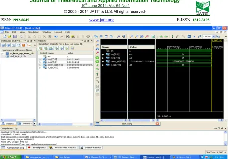
[image:6.595.92.299.235.402.2]Figure 4. Simulation Output For Inverse Byte Substitution For The Result Shown On Figure 3.
Table 2: Simulation Result Of Proposed S-Box Output For Symmetrical Within Key Bytes
128bit message input
128 bit AES S-Box Output
at first round
128 bit Proposed S-Box Output 128 bit S-box
key input 6c6c6c6c6c6c6c6c6c6c6c6c6c6c6c6c 64 bit FSR value for permutation of 8bit S-box vectors 10204080
01020408
10202040 84080010
10010220 40080480
02100108 20048040 00112233
44556677 8899aabb ccddeeff
638293c3 1bfc33f5 c4eeacea 4bc12816
7a6b5849 3e2f1c0d f2e3d0c1 b6a79485
70615243 34251607 f8e9dacb bcad9e8f
5b4a7968 1f0e3d2c d3c2f1e0 9786b5a4
2f3e0d1c 6b7a4958 a7b68594 e3f2c1d0
Table 3: Simulation Result Of Proposed S-Box Output With Symmetrical Between Key Bytes And Message Bytes
128bit message input
128 bit AES S-Box Output
at first round
128 bit Proposed S-Box Output 128 bit S-box
key input 00112233445566778899aabbccddeeff 64 bit FSR value for permutation of 8bit S-box vectors 10204080
01020408
10202040 84080010
10010220 40080480
02100108 20048040 00112233
44556677 8899aabb ccddeeff
638293c3 1bfc33f5 c4eeacea 4bc12816
00976df4 627c4ab5 8512e871 e7f9cf30
009046d6 54417696 8c1cca5a d8cdfa1a
00b35485 6e190ee5 ec5fb869 82f5e309
[image:7.595.81.517.611.731.2]ISSN: 1992-8645 www.jatit.org E-ISSN: 1817-3195
Table 4: Simulation result of proposed S-box output with unsymmetrical between key bytes and message bytes
128bit message input
128 bit AES S-Box Output
at first round
128 bit Proposed S-Box Output 128 bit S-box
key input a1ff240a879d8f21007b9f301cfd4d3a 64 bit FSR value for permutation of 8bit S-box vectors 10204080
01020408
10202040 84080010
10010220 40080480
02100108 20048040 00112233
44556677 8899aabb ccddeeff
638293c3 1bfc33f5 c4eeacea 4bc12816
9ade0165 b6f989fd 88614db9 fe595bab
81f43653 b5c493f6 88685fbb dc5c7b9f
c3e72c00 dfbd98b5 884014b9 c77d43ce
66ed37bd 0bb49b13 88f277bf cb1d3d75
process(en,ip,sel) begin
if (en='1') then
if (sel="00000001") then op<= ip(0); elsif (sel="00000010") then op <= ip(1);
elsif (sel="00000100") then op<= ip(2); 8bit input
elsif (sel="00001000") then op<= ip(3); (sel="00001000") then op <= ip(3); elsif (sel="00010000") then op<= ip(4); 1 bit output
elsif (sel="00100000") then op<= ip(5); (op) elsif (sel="01000000") then op<= ip(6);
elsif (sel="10000000") then op<= ip(7); en else op<= '0'; end if;
else op<= '0'; end if;
end process;
Figure 2. VHDL Coding And Its One Bit Selection Module Among 8 Bit Permutation
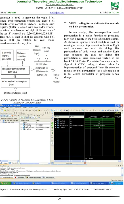
7.2. Simulation output of proposed S-box using Xilinx ISE-ISim Tool.
The figures 3 and 4 show the simulation output of the proposed design. Xilinx ISE software is used to write the VHDL coding and synthesize the design. The in-build simulation tool ISim of Xilinx ISE is used to simulate the design. The same design is used for both byte substitution at encryption and inverse byte substitution at decryption. This simulation is used to generate various output values for different input
parameters and they are tabulated in the tables 2 to 4. The entries in these tables explore the optimal possibilities of adopting proposed byte substitution technique for cryptography applications in Substitution-Permutation supported cryptosystems.
Figures 3, 4, tables 2 and 4 show the simulation output generated using Xilinx-Isim simulation tool. In the tables 2 to 4, in the third column, unusual FSR value “1020204084080010” other than the proposed set S ∈
{10,20,40,80,01,02,04,08} also used and tested. These vectors namely secondary 20 and 84 may be treated as dummy vectors. Such the dummy vectors can be randomly and carefully used at FSR to penetrate nonlinearity at the S-box output. Because, these dummy vectors are not contributing to the required non-repeated 8 bit vectors permutation in proposed S-box as described in the section 7.1.
8. CONCLUSION
transformation and delinking the algebraic expressions from direct byte substitution technique of s-box. Proposed design was simulated and synthesized using VHDL coding for Spartan3E FPGA (XC3S500E-PQG208) and the simulation was done for different values of key and S-box vectors with same 128 bit message block.
Different substitution output results were generated for a same message block and compared with 128 bit AES S-box output for optimal application of proposed algorithm. Security strength of our proposed design was justified with maximum substitution probability through the functions of choice of S-box generation, choice of s-box elements selection and key based substitution with minimum input parameters and their minimum block size.
REFERENCES
[1] J. Daemen and V. Rijmen.: The Design of Rijndael, Springer, New York, NY, USA, 2002.
[2] Advanced Encryption Standard (AES), Federal Information Processing Standards. Publication 197, November 26, 2001. [3] G. Sakthivel.: Differential Cryptanalysis of
Substitution Permutation Networks and Rijndael-Like Ciphers, Master’s project report, Rochester Institute of Technology, 2001.
[4] H. Gilbert and M. Minier.: “A collision attack on 7 rounds of rijndael,” in Proceedings of the 3rd Advanced Encryption Standard Candidate Conference, pp. 230–241, New York, NY, USA, April 2000.
[5] S. Lucks.: “Attacking seven rounds of rijndael under 192-bit and 256-bit keys,” in Proceedings of the 3rd Advanced Encryption Standard Candidate Conference, pp. 215–229, New York, NY, USA, April 2000.
[6] L. Keliher: Linear Cryptanalysis of Substitution-Permutation Networks. PhD thesis,Queen’s University, Kingston, Canada, 2003.
[7] J. Buchmann, R. Lindner, M. Ruckert, and M. Schneider.: Post-quantum cryptography: Lattice signatures. 2009. [8] Tanja Lange.: Post-Quantum Cryptography,
TechnischeUniversiteit Eindhoven, tanja @ hyperelliptic.org, 17 December 2008
[9] National Bureau of Standards (U.S.), Data Encryption Standard (DES), Federal Information Processing Standards Publication 46, 1977.
[10] PrasunGhosal, MalabikaBiswas and Manish Biswas.:Hardware Implementation of TDES Crypto System with On Chip Verification in FPGA, Journal of Telecommunications, Volume 1, Issue 1, February 2010
[11] B. Schneie.: Description of a new variable-length 64-bit block cipher, Fast Software Encryption, 191–204, 1996.
[12] R. Merkle.: Fast software encryption functions. In Advances in Cryptology: Procee- dings of CRYPTO’90. Springer-Verlag, Berlin, pp. 476–501, 1991.
[13] F. J. MacWilliams and N. J. A. Sloane.: The theory of error correcting codes I and II, Amsterdam: North-Holland Publishing Co. North-Holland Mathematical Library, Vol. 16, 1977.
[14] R. L. Rivest, A. Shamir and L. Adelman.: A method for obtaining digital signatures and public-key cryptosystems, Commun. ACM, 21(2):120-126, 1978.
[15] I. F. Blake, G. Seroussi, and N. P. Smart.: Elliptic curves in cryptography, Cambridge University Press, New York, NY, USA, 1999.
[16] C.P. Su, T.F. Lin, C.T. Huang and C.W.Wu.: A high-throughput low-cost AES processor, IEEE Communications Magazine, 41(12), 86–91, 2003.
[17] A.J. Menezes, P.C. Van Oorschot and S.A. Vanstone.:Handbook of Applied Cryptography. Boca Raton, FL: CRC, 1997.
[18] N. Masuda, G. Jakimovski. K. Aihara and L. Kocarev.: Chaotic block ciphers: from theory to practical algorithms. IEEE Trans. on Circuits and Systems – I: Regular Papers, 53(6), 1341–1352, 2006.
[19] J. Daemen.: Cipher and hash function design strategies based on linear and differential cryptanalysis, Doctoral Dissertation, March 1995, K. U. Leuven. [20] X. Zhang and K.K. Parhi.: Implementation
approaches for the advanced encryption standard algorithm.IEEE Circuits Syst. Mag., 2(4), 24–46, 2002.
ISSN: 1992-8645 www.jatit.org E-ISSN: 1817-3195
Theory and Applications, 48(2), 163– 169,2001.
[22] S.F. Hsiao, M.C. Chen, M.Y. Tsai and C.C. Lin.: System on chip implementation of the whole advanced encryption standard processor using reduced XOR-based sum-of-product operations. IEEE Proc. Inf. Secur., 152(1), 21–30, 2005.
[23] M. Matsui.: Linear cryptanalysis method for DES ciphers. In Advances in Cryptology – EUROCRYPT’93, Berlin, Germany, Springer-Verlag, pp. 386–397, 1994. [24] Biham. E and A. Shamir.: Differential
cryptanalysis of DES-like cryptosystems. Journal of Cryptology,4(1), 3–72,1991. [25] Carlisle Adams and Stafford.:The