SPECIFICATION NO. 102376
FOR THE MODEL C510 CONTROL UNIT
DATA PRODUCTS CORPORATION 8535 WARNER DRIVE CULVER CITY, CALIFORNIA
Specification Approval:
~~
J.
tJ~
Paragreph 1.0 2.0 2. I 2.2 3.0 3. 1 3.2 3.3 3.4 3.5 3.6 3.6. 1 3.6.2 3.7 3.8 3.9
3. 10 4.0
4. 1
4.1.1 4.1.2
4. I .3
4.1 .4
4. 1 .5
4.1.6
4. 1 • 7
4.2 4.2. 1
4.2.2 4.2.3 4.2.4 4.2.5 4.2.6 4.2.7 4.2.8 4.2.9 4.2.10 4.2.11 4.2.12 4.2.13 4.2.14 4.2.15 4.2.16 4.2.17 4.2.18 4.2.19
TABLE OF CONTENTS
Title
General 1
Functional Description 1
General Seek Mode Interface Description 2
General Read/Write Mode Interface Description 3
Phys i ca I Descr i pt ion 3
Packaging 3
Size 3
Weight 3
Floor Loading 3
Maintenance Panel 3
Environment 4
Operat i ng Env ironment 4
Storage and Shipping Environment 4
Power 4
Cooling 4
Cable Entry 4
Configuration 4
Functional Requirements 4
Address Storage, Use and Format 4
Fixed Head Field (Optional) 5
Operate-Next-Sector Field 5
Record Field 5
Pos it ion Fie 1 d 5
Disc Field 6
Access Channel Field 6
Parity Field 6
Control Signals and Operation Sequence 6
Select (Computer to Control Unit) 7
Address (Computer to Control Unit) 8
Complete (Control Unit to Computer) 8
Confirmed (Control Unit to Computer) 9
Busy (Control Unit to Computer) 10
Ready (Control Unit to Computer) 10
Alert (Computer to Control Unit) 11
Operate Commands (Computer to Control Unit) 11 End of Header (Control Unit to Computer) 14 Write Data Lines (Computer to Control Unit) 15 Read Data Lines (Control Unit to Computer) 15
Write Clock (Control Unit to Computer) 15
End of Record (Control Unit to Computer) 15
End (Computer to Control Unit) 15
Clear (Computer to Control Unit) 16
Wrrte Lockout Warning (Control Unit to Computer) 16 Control Unit Operable (Control Unit to Computer) 16
A I arm (Buzzer) 16
Paragraph
4.2.21 4.3 4.30 1
4.3.2 4.3.3 4.3,,4 4.3.5 4.3.6 4.3.7 4.3.8 4.3.9 4.3.10 4.3.11 4.4
500
5.1 5.2 5.3 5.3. 1
6.0 6. 1 6.2 6.3 6.3. 1 6.3.2 6.3.3 7.0 7. 1
7. 1 • 1
7. 1 .2 7. 1 .3
7.1.4 7.2 7.2.1 7.2.2 7.2.3 7.2.4 7.3 7.3. 1
7.3.2 7.3.3 7.3.4 8.0 8. 1 8.2 8.3 8.4
TABLE OF CONTENTS (Cont)
Title
Connected (Control Unit to Computer) Errors (Control Unit to Computer) Address Parity Error
Address Compare Error Wrong Command
End Error
Positioning Error Sector Error Data-In Error Data-Out Error Data Check Error
Improper Address Error Wrong Disc Unit Error System Power Control
Interface Characteristics Electrical Characteristics
Interface Signal Summary
Interface Connectors and Wiring
Computer to Control Unit Input Connector Performance
Data Transfer Rate
Components of Access Time Storage Capacity
Record Length Records Per File
Addressable Bit Capacity Acceptance Tests
Error Definitions
Incomplete Operation Error Reading Error
Writing Error Failure
Design Objectives
Incomplete Operation Error Rate Reading Error Rate
Writing Error Rate Failure Rate
Error Rate Acceptance Criteria Incomplete Operation Error Rate Reading Error Rate
Writing Error Rate Failure Rate
Ma i ntenance
Scheduled Maintenance Unscheduled Maintenance Spare Parts
Write Header Procedure
LIST OF ILLUSTRATIONS
Figure Title Page
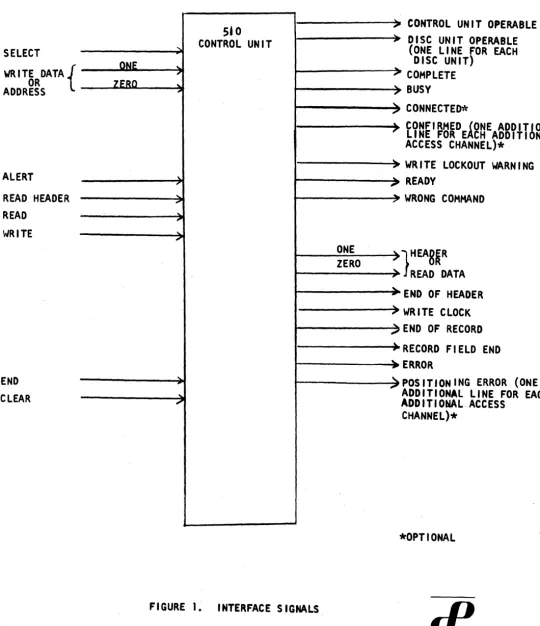
1 Interface Signals 26
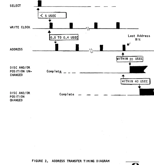
2 Address Transfer Timing Diagram 27
3 Seek Operation Timing Diagram 28
(Single Channel Operat ion)
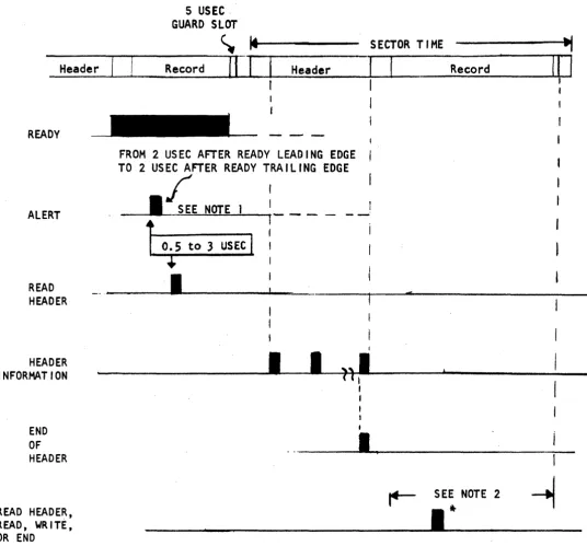
4 Read Header Timing Diagram 29
5 Data Transfer Timing Diagram 30
L 1ST OF TABLES
Table Title Page
1 Typical Sectoring Arrangements 23
1.0 GENERAL
This document is the technical specification for the C510 Control Unit, a component for the mass, random-access DISCflLE system. The C510 Con-trol Unit provides communication between a computer and the second com-ponent of a DISCflLE system, referred to herein as the Disc Unit. A DISCflLE system contains up to four Disc Units, each containing two in-dependent access channels. There are up to two Control Units per system, each capable of communicating with up to four Disc Unit channels. Options are available which allow each Control Unit to communicate with up to eight Disc Units and up to sixteen access channels.
The 510 Control Unit contains micro-miniature, integrated circuitry re-qui red to:
a. Accept and store a computer address and transfer the address to the proper Disc Unit channel.
b. Locate the addressed record and inform the computer when data may be trans ferred.
Co Read a header (the pre-recorded address data preceding each record)
and/or, read or write a record; or, under computer command, perform any consecutive number of these operations.
do Indicate errors due to improper data transfer, component malfunc-tion or improper Computer command sequence.
eo Write headers, either under computer control and by programming from the Control Unit maintenance panel.
200 FUNCTIONAL DESCRIPTION
Each Disc Unit contains up to 32 data discs. Each disc is accessed by an independent positioner which carries eight read/write heads to anyone of 64 discrete positions. Each head accesses a single track at the
se-lected position o The 510 Control Unit uses the computer address to select a Disc Unit channel and then instructs that channel to move the addressed positioner to the addressed position and select the proper read/write heado
A number of headers must then read to ensure that the proper track is being accessed. This process, referred to as track confirmation, can be per formed by the Cont ro 1 Un it, or, as an opt i on~':,' can be performed i n-ternally by the Disc Unit channel. Then, under computer command, the Control Unit controls the transfer of data to and from the selected track.
A Control Unit connected to more than a single Disc Unit channel, has multiple-seek capability; i.e., the Control Unit can address and then disconnect from each Disc Unit channel successively, thus overlapping positioninq times.
When the Disc Unit track confirmation option is not used, the Computer, after disconnecting from a Disc Unit channel, must later readdress that channel and allow the Control Unit to confirm the track. When the Disc Unit track confirmation is exercised, confirmation is performed in the Disc Unit independent of the Control Unit. Thus, after disconnecting from the channel, the Computer may return to the channel in the confirmed state and requIre only a latency delay before beginning data transfer. Thus, with this option, the Computer can overlap confirmation time as well as positioning time.
A Dual-Switch option is available which allows either of two Control Unit to connect to the same access channel. In a system utiltzing two Control Units, either Control Unit can access any of the access channels on the attached Disc Units. Thus, in a system utilizing eight attached Disc Units, each Control Unit would have access to 16 access channels.
2.1 General Seek Mode Interface Description (See Figure 1.)
Each time the computer addresses a channel, the C510 Control Unit re-sponds with a signal(s) which defines the current status of that address. The interface is designed to implement optimum time-saving operations, e.g., multiple-seek while minimizing costly and complex instruction book-keeping. The precise significance and timing characteristics of each
interface signal is specified under paragraph 4.2.
a. Each time an address is transferred, the computer is informed (Complete) if the address is accepted and is being operated upon by the selected Disc Unit channel. With this command, the computer may proceed to address another channel or may branch to another
routine.
b. Should the addressed disc area conflict with that currently addressed by the other channel, the computer is informed by Busy. The Com-puter may then supply a new address, proceed to an alternate Disc channel or routine or wait for the current disc area to be re-leased.
c. When the computer addresses a record for which the track has been confirmed, the Computer is notified (Confirmed).
d. In the confirmed state, the C510 Control Unit will generate a Ready level when the selected read/write head is about to enter the addressed record area.
2.2 General Read/Write Mode Interface Description
The C510 Control Unit supplies the computer with signals required to define the area currently under the head relative to the data desired to be transferred. The precise characteristics of these signals are covered under paragraph 4.2.
a. The computer is notified by Ready when the head is located in the sector immediately preceding the addressed sector. An Alert
fol-lowed by Read Header and/or a Read or Write command from the com-puter indicates the type of operation to be performed.
b. The computer is notified when the header area is finished (End of Header) and the record area is about to be entered.
c. The computer is notified when the last bit of record area occurs (End of Record). Finally, a time period is allotted after End of Record during which the Computer may terminate transmission (End signal) or continue (Read Header and/or Read or Write).
3.0 PHYSICAL DESCRIPTION
3.1 Packaging
3.1.1 The Control Unit is enclosed with sheet steel and contains a minimum of trim.
3.1.2 The Control Unit is painted with Data Products Corporation standard charcoal and light gray and the frame will be painted dark gray. Optional colors available.
3.2 Size
Length - 36-1/2" Height - 70" Wi dt h - 18-1/4"
3.3 Weight
445 pounds
(shipping weight: approximately 545 pounds)
3.4 Floor Loading
111 lbs on each of four casters
3.5 Maintenance Panel
An internal panel displays the status of registers and any errors which may occur and contains test switches for maintenance operations.
3.6 Environment
3.6.1 Operating Environment
850F(300C) maximum
600F(150C) minimum
8~k Maximum - relative humidity
2~k Minimum - relative humidity
3.6.2 Storage and Shipping Environment
lSOOF(6S0C) maximum
-200F(-280C) minimum
9~k maximum - relative humidity
3.7 Power
The Control Unit requires 120 vac, 50 or 60 cycles, single phase power, 1.5 KW maximum. Special voltages (105 to 125 or 208 to 240) can be accommodated.
3.8 Cooling
The Control Unit is cooled by ambient air drawn into the unit by fans.
3.9 Cable Entry
Power and signal cable entry is through the base of the unit.
3.10 Configuration
A single free-standing cabinet contains either one or two Control Units.
4.0 FUNCTIONAL REQUIREMENTS
4.1 Address Storage, Use and Format
Records stored in the Disc Unit are identified and selected by means of an address from the Computer. This address (which comprises a maximum of 24 bits separated into seven fields) is stored in the Control Unit.
Two additional bits may be required if the Dual-Switch option is used and if the number of Disc Units is extended to eight.
The Control Unit uses the address to select a Disc Unit access channel and direct it to seek the track containing the requested record. The stored address is then compared with the headers read from the track to determine when a read/write head is positioned over the proper tracko
4.1.1 Operate-Next-Sector Field
This field consists of one bit in the least significant address position. The functions executed are as follows:
4.1.1.1 Operate-Next-Sector Field ZERO
The complete address (disc, position, and record fields) is used to select a particular record.
4.1.1.2 Operate-Next-Sector Field ONE
A partial address is used to select the first available record from a selected track. The partial address is that portion of the ad-dress required to select a given track. All of the records of a particular track may be transferred in this mode without a latency delay by starting with the first available record and terminating with the sector one less than the initial header read from the track.
4.1.2 Fixed Head Field (Optional)
This field consists of one bit in the next least significant address posI-tion. A ONE in the field instructs the system to use the position and record fields to select a fixed head. This field is eliminated when the fixed head option is not used.
4.1.3. Record Field
This field consists of up to eight bits in the next most significant address positions. ThIs field is used to select one of the possible records associated with the selected posltlon. The record is selected by selecting one of the eight heads and one of the sectors associated with that head. The record addressing scheme is such that records are read from an outer track, then an inner track and continue to alternate. As an alternative, the scheme may be mechanized to select four
heads first from the outer Zone and then the four heads from the inner zone. The number of bits in the record field depends on the format selected.
During a frxed head access, the record field is used to select one of elqht heads In the group addressed by the position field.
4.1.4 Position Field
This field consists of six bits in the next most significant address positions. This field is used to select one of the 64 possible posi-tions of a movable positioner.
When addressing a fixed head, the four least significant bits of the position field are used to select one of 12 groups of fixed heads. For a fixed head the position field cannot exceed the binary equivalent of decimal eleven.
4.1.5 Disc Field
This field consists of five bits in the next most significant address positions. This field selects one of the positioners, and hence one of the discs in the selected file.
4.1.6 Access Channel Field
This field consists of two bits in the most significant address posi-tions. This field is used to address from one to four Disc Unit Access Channels. The access channels may be located in up to four Disc Units. Thus, both access channels may be selected in two Disc Units or four
access channels in four Disc Units.
The Access Channel field may be extended to four bits so that the op-tion for a total of eight Disc Units and the Dual-Switch opop-tion may be handled. In this case, the most significant bit selects channel A or B within the addressed Disc Unit. The three least significant bits select one of eight Disc Units.
4.1.7 Parity Field
The parity field consists of one bit in the most significant position. It is a bit which makes the address have an odd number of ONES.
4.2 Control Signals and Operation Sequence
4.2.1 Select (Computer to Control Unit)
This pulse logically connects the Control Unit to the Computer and prepares it to receive and store an address. The pulse also commands the Control Unit to initiate and control a sequence of operations to locate the requested record in the addressed Disc Unit channel. The Computer usually sends the Select pulse upon completion of data
transfer; however, Select may be sent at other times to permit over-lapped seeking in a mUltiple Disc Unit channel system.
The Select pulse is always followed by an address. After the Control Unit has accepted the address, it responds with one of the following three signals: Complete, Busy, or Error. A new Select is not con-sidered accepted until the Control Unit responds with one of these
signals. If another Select pulse is sent before one of these responses, a Wrong Command and an Error level will be generated within 5 micro-seconds, and the second address will not be accepted. This is because the previous address is still being operated upono
The Complete level indicates that the selected Disc Unit is attempting to locate the requested record. When performing a single-access opera-tion, the Computer will wait for Confirmed and Ready in order to operate upon the addressed track.
The Busy level indicates that the alternate channel is currently acces-sing the addressed disc area. When the channel attempts to address a fixed head, the Busy level indicates that the other channel is currently control 1 ing a fixed heado If no new Select is sent after Busy, then a Complete signal will be generated after the addressed disc area or fixed head disc is released b; the other channel. The Computer always has the alternative of clearing a Busy condition by selecting a new ad-dress.
During multiple-seek operation, the Computer can disconnect and proceed to another channel in response to Complete or Busy. For a Complete, the channel will commence moving the positioner towards the addressed location. For a Busy, the channel will wait until the addressed qroup is released and then enable the positioner.
If the Select pulse is sent during track confirmation, (between tl-_e Complete level and the Confirmed level), and the Internal Confirmation option is not used, then the confirmation process is interrupted. This may be done in a system which has several Disc Unit access channels at-tached to a Control Unit to achieve overlap seeks. The Control Unit performs the confirmation on the last channel to which it is logically connected.
When the Internal Confirmation is used, the Control Unit can be discon-nected from the channel after Complete or Busy and the channel proceeds with the track confirmation process. This permits overlapping of
confirma-tion times as well as posiconfirma-tioning times. The Control Unit alWay~
remains logically connected to the last Disc Unit channel for which it received an address.
The Error level in response to Select indicates that the original re-quest cannot be executed, or that a Select was sent out of sequence.
In any instance, a new Select will clear the error condition and ini-tiate a new seek operation. When the Select is sent out of sequence, Wrong Command is issued with the Error. An Error level and Wrong Com-mand will be generated for each Select out of sequence.
When the Dual-Switch option is used, the response to a Select pulse will include one additional possible signal, Connected. This level
indicates that the selected access channel is currently connected to the other Control Unit.
Address (Computer to Control Unit)
The Computer sends the address serially over the write data 1 ines. Address bits will be sent in the following order: operate-next-sector field, fixed head field (if used), record field, position field,
disc field, access channel field, and ~arity field with the least significant bit of each field first.
Transmission of Write Clocks begins between 0.25 and 8 microseconds after the Control Unit has received the Select pulse. The Write Clock will be issued at this time so that an internal Computer clock need not be used. The Write Clock will be issued when the Control Unit can accept the address. One Write Clock pulse will be issued for each address bit. (Write clocks may be delayed from the Select pulse when the Control Unit must complete an operation; e.g., padding a short written record with ZEROS).
Complete (Control Unit to Computer)
When the selected Disc Unit has accepted a moving-head address and has started to seek the requested record, the Complete level is issued.
If an address is issued for a channel which is already seeking that address, Complete is returned within 20 microseconds after the full address is received. If head positioner power is on when an address
is received for a different position or positioner, Complete will be returned approximately 40 microseconds after address transmis:ion. If power has been cleared prior to Select, Complete or Busy Will be returned in approximately 20 microseconds.
4.2.4 Confirmed (Control Unit to Computer)
ThIs level indicates that the selected posItioner is settled on track, in the case of a moving-head address. For fixed-head accessing, Con-firmed Indicates proper selection of the fixed head.
The seek operatIon for a moving-head address begIns when the Complete level Is Issued. The stored address is used to select a positioner, move that posItIoner to the selected position and select a head for
readIng headers. A suffici~nt number of headers on a given track are read to determine that the positioner is settled on the track. This is the eariiest point In tIme that reliable reading or writing may be performed. The process of determIning that the posItioner is settled
is called track confirmation.
4.2.4.1 Standard Interface
When the system does not contain Internal Confirmation, Confirmed is issued by the Control Unit only when it is logically attached to the access channel which it is confirming. When the computer instructs a channel to seek a position which has already been confirmed, the Confirmed level will be returned, with Complete, within 20 micro-seconds after the last address bit is received. The Confirmed level will be supplIed until a new End or Select is supplied to the Control Unit. The Control Unit will store the confIrmed condition for that channel until a new position is requested for that channel or until that channel is cleared.
When a fIxed head is se1ected, the track confirmation process
consists of reading only one header. Therefore, confIrmation occurs within one sector tIme after Complete.
4.2.4.2 Internal Confirmation
When the system contains Internal Confirmation. the Control Unit need not be logically attached to an access channel for ConfIrmed to be issued. With this option, a separate Confirmed signal for each access channel Is available to the computer. Confirmed is then
issued when the confirmation process Is completed for the particular channel. The access channel will remaIn in the confirmed state
until cleared (due to eIther a Clear pulse or a new position address).
4.2.5 Busy (Control Unit to Computer)
If the Computer requests a record located in a disc area being accessed by the alternate channel, a Busy signal will be generated within 40 microseconds. The Computer then may:
a. Wait until the alternate channel releases the disc (Complete will be returned within 10 microseconds after the disc is
re-leased); or
b. The Computer may disconnect from the busy channel by proceding to an alternate channel. The busy Disc Unit channel will hold the address and operate upon that address when the other chan-nel releases the addressed group. When the Computer returns to the channel that indicated busy, the Control Unit will re-spond with the status (i.e., still Busy or Complete) of that channe 1 •
c. Readdress the same channel with an alternate group address. The new Select clears the Busy condition and:
(i) If the new Select is received while the disc is still busy, a Complete level will be returned within 40 microseconds after the last address bit.
(ii) If the Select is received when the disc is no longer busy but before Complete, a Complete level for the new address will be returned within 40 microseconds. If the new Select
is received within 2 microseconds before the time that a Complete is issued for the original address, this Complete must be ignored by the Computer.
d. (Dual-Switch Opt ion Only) If the alternate Control Unit is not currently connected to that channel, this Control Unit may at-tempt to access the desired group through the alternate channel.
Busy is also generated when the channel attempts to address a fixed head while the other channel is accessing a fixed head in the same Disc Unit.
4.2.6 Ready (Control Unit to Computer)
The seek operation terminates with the Ready level. This level indi-cates that the track has been confirmed and that the address stored in the Control Unit agrees with the head address read from the track. The
will terminate the Ready level. The Alert pulse may also occur up to 2 microseconds after the trailing edge of the Ready level.
When the operate-next-sector bit is a ZERO, the Ready level is sent to the Computer at the end of the header which completely agrees with the disc, position, and record fields of the address stored in the Control Unit. If the Computer does not respond to a Ready with an Alert within the specified time, the Ready level for that record is sent on the next
revolution of the disco The Control Unit, however, logically djscon-nects from the Computer at the end of this record and does not accept an Alert until after the next Ready is sent.
If the operate-next-sector bit is a ONE, then the Ready level is sent as soon. as the positioner is settled on the track. The Ready level is sent after each header is read until an Alert pulse is received.
When a fixed head is addressed, the Ready occurs with Confirmed if next-sector is ONE or within one disc revolution jf operate-next-sector is ZERO.
When the Internal Confirmation option is used, the Confirmed signal is issued one sector earlier than when confirmation is performed in the Control Unit. Hence, for this case, the minimum time between Confirmed and Ready is one sector time.
4.2.7 Alert (Computer to Control Unit)
The Alert pulse logically prepares a Control Unit to receive a Read Header and/or a Read or Write pulse. The Alert pulse may occur any
time from 2 microseconds after the leading edge of Ready to two micro-seconds after the trailing edge of Ready.
4.2.8 Operate Commands (Computer to Control Unit)
The operate commands are:
a. Read Header b. Read
c. Wri te
The operations performed by these commands are discussed in para-graphs 4.2.8.4 through 4.2.8.6. The Read Header pulse may be sent alone or concurrently with a Read or Write pulse. During a continue mode, Read and Write commands may be interlaced in successive sectors. Only one command or one concurrent combination of commands may occur
in anyone sector. The occurrence of two non-concurrent commands in the same sector results in a Wrong Command error~
4.2.8.1 Initial Operate Timing
For an initial operation, an operate command Is sent between 0.5 and 3 microseconds after the Ale:t pulse and normally causes the operation to be executed in the following sector. No new command will be
accepted until after the End of Header pulse for that following sector.
4.2.8.2 Continue Mode Timing
For a read or write continue, a new operate command should be sent any time during data transfer or in a time slot of 5 microseconds after the End of Record pulse.
For a read header continue operation, a new operate command may occur any time between the End of Header pulse and up to 5 micro-seconds after End of Record.
4.2.8.3 Operate/Skip Sector Timing
When a Read or Write command is sent in conjunction with a Read Header command, the Computer can use the approaching header information to decide whether to operate in that sector or to skip to the following sector. This "skip sector" function can also be used to supercede a Read or Write command when no Read Header function is involved. Note that the Computer may operate in the approaching sector simply by permitting the just issued Read or Write command to be processed.
Should the Computer decide not to operate in the sector for which the Read or Write commands were issued, a new operate command(s) occurring within two microseconds after the End of Header pulse will supercede the previous commands. The record register will then be incremented by one and the new command will be performed in the following sector.
The response to a command occurring between the end of the 2 micro-second time slot and the beginning of data transfer is dependent upon the operation previously commanded. When a Read command is being processed, a hew operate command occurring between 2 micro-seconds after End of Header and the beginning of data transfer will result in a skip sector operation. A Read command occurring after the beginning of data transfer will terminate that read operation; the file will then proceed to the next sector as for a normal read continue operation.
is processed, is an illegal command and is responded to with an Error indication.
4.2.8.4.
Read HeaderWhen the Control Unit receives this pulse, the stored address is incremented by one and the associated 21-blt header is transmitted to the Computer. The header information is trans-mitted on the data lines and has the same format as the
original address except that the operate-next-sector bit and the access channel field are not transmitted. A parity bit is transmitted as the final bit. An End of Header pulse will be transmitted concurrent with the parity bit. Successive headers may be read by supplying Read Header within the required time
limitations.
When the read header operation is addressed to a fixed head, a ONE is in the fixed head field position.
4.2.8.5.
ReadThe Read pulse causes the Control Unit to increment the stored ad-dress by one.
Then the header address associated with the record to be operated on is compared with the incremented address (the extent of the compare depending on the operate-next-sector bit). Hence, the header of the first record in which reading will be performed is the address originally received from the Computer augmented by one. The Control Unit commences to transmit the data read from the ad-dressed record. The number of bits in the record depends upon the selected format. An End of Record pulse is issued concurrent with the last data bit read unless an End pulse or a new Read or Write command is received during reading of data.
When a Read pulse is given during data transfer or in the time slot after End of Record. the following record will be read. This opera-tion of reading the following record may be repeated so that all records which correspond to a given position are read sequentially. The Initial binary number in the record field may be any number. The system can execute this mode of operation indefinitely.
When addressing fixed heads the read continue mode may be utilized until all records associated with the
96
fixed heads are read. This mode may continue indefinitely.If a Read pulse Is given during data transfer, the transfer will be Interrupted, and the requested operation will begin In the next sector.
4.2.8.6.
Write (Computer to Control Unit)4.2.9
The Write pulse causes the Control Unit to increment the stored ad-dress by one. When the record portion of the sector associated with the incremented address comes under the head, the Control Unit begins emitting Write Clocks. Each Write Clock must be responded to with a data bit.
An End of Record pulse is transmitted to the Computer concurrent with the Write Clock which requests the last write data bit unless an End pulse or a new Read or Write command is received during writing of data.
When an operate command or an End pulse is given during the writing of a record, the Write Clocks to the Computer will be interrupted, the remainder of the record will be filled with ZERO bits, and any requested continue operation will be executed in the next sector. The operation of writing the following record may be repeated so that all records which correspond to a given position are written sequentially. The same method of sequential accessing is used for write as is used for read. It is important to note that no more than the total number of records for a position can be written se-quentially without destroying information not yet read. This count must be kept by the Computer, although the Record Field End pulse may be used as a reference. The write continue mode may also be used to write consecutive records for all the records on the fixed head disc. The Computer must also keep this count to ensure that data is not erased before it is read (although the Record Field End pulse may be used as a reference).
End of Header (Control Unit to Computer)
This pulse is sent in response to any operate command. The pulse is always sent immediately after the last header bit is read whether the Computer has requested header information or not. Thus, this pulse
4.2.10 Write Data Lines (Computer to Control Unit)
Two lines are used for the transmission of write data; one line for data ONE's and one for data ZERO's.
During the write operation and the transfer of address, the Computer transmits over the Write Data Lines in response to Clock pulses sent by the Control Unit. The Clock pulses are gated back over the Write Data Lines as ONE's or ZERO's within 0.0 to 0.4 microseconds. The delay time is determined by the propagation time of the line and the Computer delay and is measured at the Control Unit interface.
4.2.11 Read Data Lines (Control Unit to Computer)
Two lines' are used for transmission of read data or address header bits; one line for ONE's and one line for ZERO's.
The time between any two consecutive data pulses shall not vary from the average data rate by more than
t30%.
4.2.12 Write Clock (Control Unit to Computer)
The write clock pulses are sent during a write operation when the head reaches the portion of the track to be written. Transmission of these pulses ceases upon receipt of a new operate command or an End pulse. If an End pulse is received no more write clocks will be transmitted; however, if a Write pulse is received the pulses will again be sent when the head reaches the next record to be written. The write clock pulses are generated from information read from the
clock tracks of the control disc.
The write clock pulses are also sent in response to a Select. These pulses are used by the Computer to clock the transmission of the address. One write clock will be issued for each address bit. The write clock pulses may be delayed from Select in order to permit the Control Unit to complete an operation (e.g., padding a sector after a short record is written).
4.2.13 End of Record (Control Unit to Computer)
This pulse will be transmitted at the end of a read, write or read header operation unless data transfer is interrupted by End or a new operate command. During a Read operation the puls;e will be transmitted coincident with the last bit of the record. During a Write operation the pulse will be transmitted coincident with the Write Clock used to gate the last write data bit from the Computer. During a read header operation, this pulse is issued prior to the end of the sector in order to define the beginning of the 5 microsecond ,time slot which is avail-able for a new command.
4.2.14 End (Computer to Control Unit)
The End pulse is used by the Computer to discontinue communication. The End pulse also disconnects the selected Control Unit from the
Computer and the Control Unit is then ready to receive a new Select. Upon receipt of the End pulse, the Control Unit transmits no more
than one clock pulse or data bit.ror a read or write operation,; the End pulse may be sent any time after data transfer has begun, or during the 5-microsecond time slot after End of Record. For a read header operation, the End pulse may be sent any time from the End of Header to 5-mlcrosecond after End of Record. At the sector mark following End, the Control Unit will disconnect from the access channel.
During a fixed-head access, End clears the Fixed-Head Select signal, releasing the fixed-head disc for accessing by the other channel. Clear (Computer to Control Unit)
The Clear pulse is used to interrupt the "position hold" state of a Disc Unit channel. The positioner circuits are designed so that the read/write heads remain over the addressed track until a Clear or Select with a different disc and/or position address is
re-ceived by the Control Unit. The Clear pulse may be sent any time between the beginning of Complete and Alert or simultaneously with End or up to 10 microseconds after End. It should be noted that Clear is not necessary following a fixed-head access. The Clear pulse will be used by the access channel currently connected to the Control Unit and will disconnect that channel from the Control Unit. 4.2.16 Write Lockout Warning (Control Unit to Computer)
Data written onto the disc may be preserved for reading only. Switches are provided in the Disc Unit to manually prevent erasing and writing on any selected disc or discs from both channels. Addressing a locked-out disc results in a level on the write locklocked-out warning coincident with Confirmed or Complete, whichever comes last.
The fixed head disc may also be locked-out. Locking out this disc inhibits erasure and writing from both channels.
If the Controller attempts to write data, writing or erasure is in-hibited and a Wrong Command and Error level are generated.
4.2.17 Control Unit Operable (Control Unit to Computer)
When the Control Unit Is operable and available to receive commands from the Computer, an active level indicates Control Unit operable. The Control Unit is not operable when any of the test mode switches are in a test position or when the internal temperature of the Con-trol Unit exceeds the operational level.
4.2. 18 Alarm (Buzzer)
4.2.19 Disc Unit Operable (Control Unit to Computer)
4.2.20
An operable line will be available for each attached Disc Unit. An active level indicates that the associated Disc Unit is operable and available to receive commands from the Computer.
Record Field End (Control Ui..,it to Computer)
This pulse indicates that the last record of the record field is about to be operated on. The pulse shall occur simultaneously with the End of Header pulse. For a fixed head operation, this pulse occurs In the sector corresponding to the highe3t order address on the fixed head disc.
4.2.21 Connected (Control Unit to Computer)
This level is used as a response to the Select pulse to indicate that the selected access channel is currently connected to the other Control Unit when the Dual-Switch option is used. The address received by the Control Unit will not be transferred to the Disc Unit access channel and the Select operation will be terminated. The Connected level will be active within 10 microseconds after the last address pulse has been received.
4.3 Errors (Control Unit to Computer)
An Error level is transmitted to the Computer in response to any of the conditions to be discussed. The Wrong Command error is also supplied on a separate line. When the Internal Confirmation option is used, four additional lines (one for each access channel) carry the positioning error 1 eve 1 •
The Control Unit external Control Panel contains a FAULT indicator which lights in response to any error condition.
Additional internal error indicators are provided on the maintenance panel. It is possible to eliminate all but electromechanical error con-ditions by issuing a new Select to the file. Electromechanical malfunction
is indicated by an inactive level on the Operable channel; this condition cannot be reset electronically since m~~ual interruption is required.
Any error which occurs during the seek and/or confirmation process will prevent a Ready pulse from being issued; hence, no read or write operation can be performed on the addressed record. If an Error level occurs after
ready but before transmission of data, a read or write operation is still inhibited. When an error occurs during transmission of data, the val idity of the data being read or written is spurious. An error occurring after data transmission is finished indicates that no End, or new operate command was received from the Computer.
4.3.1 Address Parity Error
This error condition exists if the address parity bit not give odd parity to the address transmitted and is sponse to the last address bit. If an address parity Error level is transmitted to the Computer and the PE i nd i cator is 1 it.
as received does generated in re-error exists, an
(par i ty errot: ... ) _ _ _
J1
4.3.2
4.3.3
4.3.4
4.3.5
4.3.6
Address Compare Error
After the address is transferred between the Disc Unit shift regis-ter and positioner storage regisregis-ter, the contents of the two regisregis-ters are compared. Bad comparison results in an address compare error. With Internal Confirmation, another condition is checked. After the Disc Unit confirms the disc and position, a final validation is per-formed on the header by the Control Unit and Disc Unit simultaneously. If the Control Unit cannot compare the disc and position portion of the header being validated by the Disc Unit, an address compare error also exists. Either of these conditions lights the compare (C) lamp and an Error level is transmitted to the Computer.
Wrong Command
This error occurs for anyone of five conditions; (1) a Select pulse occurring between a previous Select and the response of Complete, Busy, or Error, (2) a Select pulse occurring betwen the beginning of data transfer and End, (3) a Write pulse
occur-ri ng for a locked-out disc, (4) two non-concurrent operate com-mands occurring in the same sector, (5) an illegal Write pulse occurring as per paragraph 4.2.8.3. For each of these cases, Error and Wrong Command leve1s are issued and the WC (wrong command) i nd i cator j s 1 it.
End Error
If, after reading or writing a record, an End, Read Header, Read or Write pulse is not received during the 5-microsecond time slot, an End error exists. An Error level is transmitted to the Computer and the END indicator is lit.
Positioning Error
If the track confirmation process is not complete within approximately 400 milliseconds after Complete, a positioning error exists. An Error
level is transmitted to the Computer and the DP (disc position) indi-cator is lit.
When the Internal Confirmation option is selected, the positioning error is determined in the Disc Unit and not the Control Unit. In this case, there is a positioning error line for each access channel attached to the Control Unit. The positioning error would not cause an Error level to be issued, since the positioning error for each ac-cess channel is brought out as a separate signal.
Sector Error
The sector error condition exists if, approximately 200 milliseconds after the positioner is confirmed, the desired record cannot be found, This condition prevents a Ready pulse from being transmitted. Also,
4.3.7. Data-In Error
4.3.8
4.3.9
The data-in error exists if the Computer does not respond to a WrIte Clock pulse with a data ONE or data ZERO within the specified tIme or
if data Is entered without clock requests. An Error level is trans-mitted to the Computer and the Dl (data-in) Indicator is lIt.
Data-Out Error
This 2rror exists if any two successive data pulses from the Disc Unit are separated in time by more than 150% of the normal time separatlon~ This check is performed on read data during a read operation and "echo check" data during a write. operation. An error condition sends an Error level to the Computer and lights the DO (data-out) Indicator.
Data Check Error
During a write operatIon, a bit-by-bit comparison is continually made between the data transmitted by the Control Unit and the data content of the write current. Bad comparison results in an Error level to the Computer and lights the DC (data check) indicator.
4.3.10 Improper Address Error
An improper address error is generated when the Control Unit receives an address for which the Computer does not respond for Write Clock pulses, or an invalid address. An invalid address Is either an ad-dress containing a ONE in the fixed-head field and ONE's in any of the least significant four bits of the disc field or the two most significant bits of the position field, or an address in which the four least significant bits of the position field contain a binary number greater than decimal 11. An improper address error also exists when a Disc Unit does not respond to an address from the Control Unito In response to any improper address, an Error level
is sent to the Computer and the lA (improper address) error indicator is 1 it.
4.3.11 Wrong Disc UnIt Error
When the Control Unit accesses a Disc Unit, a comparison is made between the Disc Unit address and the unit number lInes from the Disc Unito Bad comparison results in a Wrong Disc Unit Error. Either condit,lon I ights the Wrong Disc Unit (WDU) lamp and trans-mits an Error level to the Computer.
4.4 System Power Control
Primary power to each DIsc Unit is supplied through its own circuit breaker. Disc Unit power sequencing Is Initiated over the Control Unit access channels. Up to eight ENGAGED/DISENGAGED switches, located on the Control Unit maintenance panel, control power sequencing to each of the attached Disc Units. Placing a switch in the ENGAGED position
permits the associated Disc Unit to sequence up and be operable. When the Disc Unit is sequenced up, it is prepared to receive commands from access channel. When disengaged by both access channels, the Disc Unit can still be sequenced-up by switches located on its own control panel.
5.0 INTERFACE CHPRACTERISTICS
5.1 Electrical Ch31-acteristics
The standard interface uses current levels and current pulses. The cur-rent is supplied from a positive voltage and is referenced at a nominal
+6 volts for'the transmitter and a +1 volt for the receiver. Simplified circuit diagrams of the transmitter and receiver are shown in the illus-tration below.
TRANSMITTER RECEIVER
TO VOLTAGE . DISCRIMINATOR
HIGH r+7V LOW.J +sV'
1.2KOhms
+lSV
Current Mode Interface Logic
There are two standard current states. The LOW state is the quiescent state for pulses and is represented by less than two mill iamperes. The HIGH or active pulse state is represented by 9 + 2 milliamperes. Transi-tions between the states should occur between
fa
and 100 nanoseconds. A pulse should remain at the high state for more than 20 nanoseconds and should remain above the 50% level for between 80 and 200 nanoseconds.5.2 Interface Signal Summary
Twenty-four signals constitute the standard interface. There is an
Position-5.3 Interface Connectors and Wiring
The interface connector specified below will mate with the connector in the Control Unit.
5.3.1 Computer to Control Unit input connector:
Elco 00-8017-100-000-012, keyed 1 to 1, suppl ied by Data Products Corporation (cable is suppl ied by the customer).
5.3.2 The interface signals and the signal type (pulse or level) are sum-marized below.
SIGNAL
SIGNAL
TYPE
SELECT
PULSE
COMPLETE
LEVEL
BUSY
LEVEL
CLEAR
PULSE
READY
LEVEL
ALERT
PULSE
END OF HEADER
PULSE
READ HEADER
PULSE
END OF RECORD
PULSE
~t"CONNECTED
LEVEL
CONTROL UNIT
LEVEL
OPERABLE
DISC UNIT
LEVELS
OPERABLE
(ONE liNE FOR
EACH DISC UNIT)
CONFIRMED
LEVEL
*(ONE liNE FOR
EACH ACCESS
CHANNEL)
~t"OPT
I ONAl
SIGNAL
END
ERROR
READ
WRITE
WRITE DATA
ONE
WRITE DATA
ZERO
READ DATA
ONE
READ DATA
ZERO
WRITE LOCKOUT
WRONG COMMAND
RECORD FIELD
END
*POSITIONING ERROR
(ONE liNE FOR EACH
DISC UNIT)
6.0
6.1
6.2
PERFORMANCE
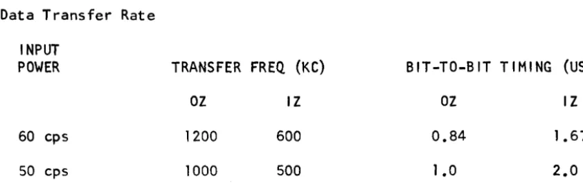
Data Transfer Rate
INPUT
POWER TRANSFER FREQ (KC) BIT-TO-BIT TIMING (USEC)
OZ IZ OZ IZ
60 cps 1200 600 0.84 1 .67
50 cps 1000 500 1 •
a
2.0Components of Access Time
The only component of access fime affected by the Control Unit is track confirmation. When the Internal Confirmation option is used, then track confirmation is performed within the Disc Unit and can be eliminated as an access time factor by utilizing multiple-seek.
The track confirmation procedure for moving-head accesses assures that the head is reliably settled on the addressed track; this is the earliest time at which a Ready pulse can be issued. The Control Unit adds a mini-mum of 39 mill iseconds (60 cps) o~ 50 milliseconds (50 cps) to all moving-head access times for track confirmation. Confirmation time for a fixed-head access is up to one sector time. It should be noted that data is not transferred until the sector following the Ready pulse.
6.3 Storage Capacity
The total storage capacity of each Disc, Unit, including synchronizing the at ignment tolerance bits is 764.608,512t
bits. The synchronizing and toler-ance bits are under control of the Control Unit and are not directly ad-dressable.
When fixed heads are utilized, the maximum total storage capacity is in-creased by 4,480,128.
6.3.1 Record Length
Record Length is wired into the Control Unit and is selectable at the time of order. At time of order, a supplement to this specification will delineate the customer1s format requirements.
6.3.2 Records Per File
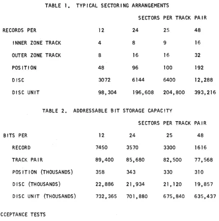
Table 1 lists typical record formats. The specification supplement will delineate the record structure for the system ordered.
6.3.3 Addressable Bit Capacity
[image:26.631.110.531.102.242.2]7.0
When fixed heads are utilized, additional addressable bits are available equivalent to 12 positions.
TABLE 1. TYPICAL SECTORING ARRANGEMENTS
SECTORS PER TRACK PAIR
RECORDS PER 12 24 25 48
INNER ZONE TRACK 4 8 9 16
OUTER ZONE TRACK 8 16 16 32
POSITION 48 96 100 192
DISC 3072 6144 6400 12,288
DISC UNIT 98,304 196,608 204,800 393,216
TABLE 2. ADDRESSABLE BIT STORAGE CAPACITY
SECTORS PER TRACK PAIR
BITS PER 12 24 25 48
RECORD 7450 3570 3300 1616
TRACK PAIR 89,400 85,680 82,500 77,568
POSITION (THOUSANDS) 358 343 330 310
DISC (THOUSANDS) 22,886 21 ,934 21,120 19,857
DISC UNIT (THOUSANDS) 732,365 701,880 675,840 635,437
ACCEPTANCE TESTS
A system consists of up to two Control Units and from one to four Disc
Unit~
The system shall be accepted at the Data Products Corporation plant afterthe test defined in Data Products Corporation Test Specification
has run for 48 hours. The error rate for acceptance is defined below.
7. 1 Error Def in it ions
7. 1 • 1 I ncomp 1 ete Ope rat i on Error
The equipment is given a command not involving data transfer, and does not complete the operation (or an error is generated for a condition which is not a data error) and then the equipment completes the opera-tion within three successive attempts.
*
Optionally, a system may contain up to eight Disc Units. [image:27.617.116.547.124.558.2]7.1.2 Reading Error
A data error is detected or the equipment ceases to operate during data trans fer ina read operat i on other than a wr i te chec\(;';" , and any of three repeated reading operations is error free.
7.1.3 Writing Error
A
data error is detected or the equipment ceases to operate during data transfer in a writing operation or during the operation ofread-ing data not previously read, and a repeated writread-ing operation is error free and yields data which may be read without error in a write chec\(;~ within three repeated attempts.
7.1.4 Failure
A
condition or malfunction which causes errors and which can only be corrected by unscheduled maintenance.7.2 Design Objectives
The design objectives of the system for field operation are as 1 isted below:
7.2.1 Incomplete Operation Error Rate
1 in 106 data operations.
7.2.2 Reading Error Rate
1 in 1010 data bits transferred.
7.2.3 Writing Error Rate
1 in lOll data bits transferred.
7.2.4 Failure Rate
1 error fo?)300 hours of cumulative fi le operation.
7.3 Error Rate Acceptance Criteria
7.3.1 Incomplete Operation Error Rate
Not more than 1 in 105 ope rat ions.
7.3.2 Reading Error Rate
1 in 109 data bits transferred.
revolu-7.3.3 Writing Error Rate
1 in 10 10 data bits transferred.
7.3.4 Failure Rate
Not more than four during the acceptance test. If the replaced com-ponent is a disc or positioner, the run-in time should be 1/16 of the test time accumulated when the failure occurs.
8.0 MAINTENANCE
8.1 Scheduled Maintenance
Routine scheduled preventive maintenance procedures will normally require about 1 man-hour per month. This maintenance should be performed by suit-able trained and competent customer personnel. The schedule for routing preventive maintenance shall be in accordance with the preventive mainten-ance procedures recommended by the vendor in the instruction manual and in customer information bulletins.
8.2 Unscheduled Maintenance
The unscheduled maintenance will not normally exceed an average repair time of on~ hour per month, if parts and maintenance personnel are avail-able.
8. 3 Spa re Part s
Spare parts will be functionally interchangeable with like assemblies, subassemblies, and replaceable parts as found within the system. They must also be physically interchangeable, one with another. A list of spare parts will be suppl ied to the customer.
8.4 Write Header Procedure
Headers may be written by manual operation from the test panel or under computer control. In either case, the Control Unit is first switched into the write header mode. Using the test panel, the operator selects the de-sired disc and position and all headers for the position are automatically written. Us ing the Computer, the Control Unit wi 11, i'n response to a Select and Disc and Position address, automatically write all headers for the position. When all headers are written, the Control Unit supplies Complete. The Computer may then select the next desired position.
SELECT
WRITE DATA {
OR
ADDRESS
ALERT
READ HEADER
READ
WRITE
END
CLEAR
ONE: lE:RO560
"
CONTROL UNIT
....
,
.... ~'"
, ".,
",
... ~ONE
ZERO
.....
..."
>
~..
CONTROL UNIT OPERABLE
DISC UNIT OPERABLE
(ONE LINE FOR EACH
DISC UNIT)
,
COMPLETE
BUSY
"-,
'"
,
>
) '",
...
.,-'"
,
'"
, ....
) ... " , ). "-lflii'"
,
CONNECTED*
CONFIRMED (ONE ADDITIONAL
LINE FOR EACH ADDITIONAL
ACCESS CHANNEL)*
WRITE LOCKOUT WARNING
READY
WRONG COMMAND
1
HEA8lR
J
READ DATA
END OF HEADER
WRITE CLOCK
END OF RECORD
RECORD FIELD END
ERROR
POSITIONING ERROR (ONE
ADDITIONAL LINE FOR EACH
ADDITIO~L.ACCESS
CHANNEL)*
[image:30.624.58.598.137.763.2]SELECT
WRITE CLOCK
ADDRESS
DISC AND/OR
POSITION
UN-CHANG'ED
DISC AND/OR
POSITION
OiANGED
-I
-
-[<
5 USEe..
)
I
I
\'
\I
0.0 TO 0.4 USE
I
I
\\
I
Comp let!t, _ _ _
Complete
-FIGURE 2. ADDRESS TRANSFER TIMING DIAGRAM
-I
Last Address Bit
16?
t
~ITH
IN 20 USECI
+
[image:31.620.73.581.193.739.2]CHANNEL
ALREADY
CONFIRMED
COMPLETEI
CONF
rRME_.D ....
I
________ _
CHANNEL ALREADY
CONFIRMED AND
II
OPERATE-NEXT-SECTOR READY
1
t
CHANNEL ALREADY
CONFIRMED AND
RECORD ADDRESS SPECIFIED
_ !EA!:!. ... _ _
... _ _
LATENCY
j
POSITION CHANGED
t
MOTION AND CONFIRMATION TIME
POSITION CHANGED AND
OPERATE-NEXT-SECTOR
-CONFIRMED
1*
j
READY. _ _ _
1
______
M_OT_I_O_N_A_N_D_C_O_N_F_IR_AA_T
__
IO_N_T_I_M~~
____
~l
POSITION CHANGED AND
RECORD ADDRESS SPEtlEIED
READY
I
*
With Internal Confirmation, Confirmed will be returned one sector earlier. [image:32.612.69.581.89.775.2]5 USEC .
GUARD SLOT
~
--~----H-e-a-de-r---',-""/ --Re-c-o-r-d
--rI_1
-II
HeaderREADY
ALERT
READ
HEADER
HEADER
INFORMATION
END
OF
HEADER
READ HEADER,
READ, WRITE,
OR
ENDFROM
2USEC AFTER READY LEADING EDGE
TO
2USEe AFTER READY TRAILING EDGE
J
•
SEE NOTE
11
-0.5
to3
USEe
I
SECTOR TIME
Record
Note 1. Alert occurrIng before End of Record time terminates Ready.
Note 2. An operate command issued at this time will be executed in the next Sector; an End pulse will logically disconnect the Control Unit.