AUTONOMOUS RE-CONFIGURATION SYSTEM WITH
ROUTE STABILITY IN WIRELESS NETWORKS
1K. MUTHULAKSHMI, 2Dr. K. BASKARAN
1
Assoc. Prof, Electronics and Communication Engineering, Park College of Engineering and Technology,
Coimbatore,Tamil Nadu, India
2
Assoc. Prof, Computer Science Engineering, Government College of Technology, Coimbatore,
Tamil Nadu, India.
E-mail:1 [email protected]
ABSTRACT
In multihop wireless networks experience frequent link failure caused by channel interference, dynamic obstacles, and bandwidth demands. Because of this degradation the wireless networks require expensive manual network management recovery. This paper presents an autonomous network reconfiguration system (ARS) using AOMDV protocol and acknowledgement reception .The ARS enables the multi radio, wireless networks to autonomously recover from local link failure to preserve the network performance. The ARS provides necessity channel assignment changes with the help of the AOMDV protocol to improve performance . AOMDV uses the channel average non fading duration as a routing metric to select the stable link for path discovery and applies a preemptive hands-off strategy to maintain a reliable connection by exploiting channel state information.After the data transmission concern receiver provides the acknowledgement notification to the transmitter node via an alternate path.The evaluation results show the network path becomes stable and no data loss can be occurred. The overall system performance efficiency by more than 90%.
Keywords: Autonomous reconfiguration system, AODV, AOMDV, Wireless link failure and Random Way point Model.
1. INTRODUCTION
Wirelessnetworks are being developed actively and deployed widely for a variety of applications, such as public safety, environment monitoring, and citywide wireless Internet services. , due to heterogeneous and fluctuating wireless link preserving the required performance of such wireless networks is still a challenging problem. For example, some links of a network may experience significant channel interference from other coexisting wireless networks. Some part of the network might not be able to meet increasing bandwidth demands from new mobile users and applications. Links in a certain area (e.g ,a hospital) might not be able to use some frequency channel because of spectrums etiquette or regulation.
Even though many solutions for wireless networks to recover from wireless link failures have been proposed, they still have several limitations as follows. First, resource allocation algorithms can provide (theoretical) guidelines for initial network resource planning. Even though their approach
provides a comprehensive and optimal network configuration plan, they often require “global” configuration changes, which are undesirable in the case of frequent local link failures. Next, a greedy channel assignment algorithm can reduce the requirement of network changes by changing the settings of only the faulty link. However, this greedy change might not be able to realize full improvements, which can only be achieved by considering configurations of neighboring mesh routers[1] in addition to the faulty link. Third, fault tolerant routing protocols, such as local rerouting or multipath routing, can be adopted to use network level path diversity for avoiding the faulty links. However, they rely on detour paths or redundant transmissions, which may require more network resources than link level network reconfiguration.
reconfiguration planning algorithm that identifies local configuration changes for the recovery while minimizing changes of healthy network settings. ARS first searches for feasible local configuration changes available around a faulty area, based on current channel and radio associations. By imposing current network settings as constraints, ARS identifies reconfiguration plans that require the minimum number of changes to the healthy network settings.
Next, ARS also includes a monitoring protocol that enables a wireless network to perform real time failure recovery in conjunction with the planning algorithm. The accurate link-quality information from the monitoring protocol is used to identify network changes that satisfy applications’ new Qos demands or that avoid propagation of Qos failures to neighboring links (or “ripple effects”). Running on every mesh node, the monitoring protocol periodically measures wireless link conditions via a hybrid link quality measurement technique. Based on the measurement information, ARS detects link failures and/or generates Qos aware network reconfiguration plans upon detection of a link failure. ARS have been implemented and evaluated extensively via experimentation on our multiracial wireless network test bed as well as via ns2-based simulation. Our evaluation results show that ARS outperforms existing failure recovery methods such as static or greedy channel assignment and local rerouting. Firstly, ARS’s planning algorithm effectively identifies reconfiguration plans that satisfy the applications’ Qos demands to the maximum accommodating twice more flows than static assignment. Secondly, ARS avoids the ripple effect via Qos-aware reconfiguration planning, unlike the greedy approach .Third ARS local configuration networks improve throughput and channel efficiency by more than 92% respectively over the local routing scheme.
Further, we provide a detailed theoretical analysis of the lifetimes of both protocols and expressions for performance with respect to routing control overhead, throughput, and packet delivery ratio. We derive a new expression for the expected lifetime of a live-die-live again system of multiple fading paths[2]. These expressions allow us to show the superiority of AOMDV over AODV, verified by simulations. Theoretical and simulation results are well matched.
2. EXISTING SYSTEM:
A.Methodology Used:
i. Greedy channel assignment
ii. Qos demands iii. IEEE 802.11 iv. AODV protocol
B. Limitation Of Existing Approaches
We now discuss the existing approaches for self-reconfigurable wireless networks.
I.localized reconfiguration:
Network reconfiguration needs a planning algorithm that keeps necessary network changes (to recover from link failures) as local as possible, as opposed to changing the entire network settings. Existing channel assegment and scheduling algorithms provide holistic guidelines such as throughput bounds and scalability for channel assignment during a network deployment stage. However, the algorithms do not consider the degree of configuration changes from previous network settings, and hence they often require globalnetwork changes to meet all the constraints, akin to edge coloring problems . Even though these algorithms are suitable for static or periodic network planning, they may cause network service disruption, and thus are unsuitable for dynamic network reconfiguration that has to deal with frequent local link failures. The greedy channel assignment algorithm, which considers only local areas in channel assignments, might do better in reducing the scope of network changes than the above mentioned assignment algorithms. However, this approach still suffers from the ripple effect, in which one local change triggers the change of additional network settings at neighboring nodes due to association dependency among neighboring radios. This undesired effect might be avoided by transforming a mesh topology into a tree topology, but this transformation reduces network connectivity as well as path diversity among mesh nodes. Finally, interference aware channel assignment algorithms can minimize interference by assigning orthogonal channels as closely as possible geographically. While this approach can improve overall network capacity by using additional channels, the algorithm could further improve its flexibility by considering both radio diversity (i.e., link as association) and local traffic information. If channel is lightly loaded in a faulty area, the second radio of node can associate itself with the first radio of node , avoiding configuration changes of other links
II.qos-awareness:
provide approximately optimal network configurations. As pointed out earlier, these algorithms may require global network configuration changes from changing local Qos demands, thus causing network disruptions. Instead, we need a reconfiguration algorithm that incurs only local changes while maximizing the chance of meeting the Qos demands. For example, if link experiences a Qos failure on channel 1, then one simple reconfiguration plan would be to associate R1 of node H to R2 of node E in channel 5, which has enough bandwidth.
Iii.cross-layer interaction:
Network reconfiguration has to jointly consider network settings across multiple layers. In the network layer, fault-tolerant routing protocols, such as local rerouting or multipath routing, allow for flow reconfiguration to meet the Qos constraints by exploiting path diversity. However, they consume more network resources than a link reconfiguration because of their reliance on detour paths or redundant transmissions. On the other hand, channel and link assignments across the network and link layers can avoid the overhead of detouring, but they have to take interference into account to avoid additional Qos failures of neighboring nodes.
Iv.review of aodv protocol:
AODV is a single path, on demand routing protocol. When a source node, NS, generates a packet to a particular destination node, nd, it
broadcasts a route request (RREQ) packet. The RREQ contains the following fields <SourceIPaddress,
Source sequence number, Broadcast ID,
Destination IP address, Destination sequence number, hop-count>,
Where the source and destination IP addresses remain constant for the lifetime of the network, the source sequence number is a monotonically increasing indicating pocket “freshness,” destination sequence number is the last known sequence number for nd at ns and hop count is
initialized to zero and incremented at each intermediate node which processes the RREQ. A RREQ is uniquely identified by the combination of a source sequence number and broadcast id. An intermediate node only processes a RREQ if it has not received a previous copy of it. If an intermediate node has a route to nd with a destination sequence number at least that in the RREQ, it returns a route reply (RREP) packet, updated with the information that it has. If not, it records the following information: source IP
address, source sequence number, broadcast id, destination IP address and expiration time for reverse path route entry, and forwards the RREQ to its neighbors.
Like the RREQ, a RREP is only processed on first sighting and is discarded unless it has a greater destination sequence number than the previous RREP or the same destination sequence number but a smaller hop count. The RREP packet contains the following fields:
<Source IP address, Destination IP address, Destination
sequence number, hop-count,
Route expiration time>
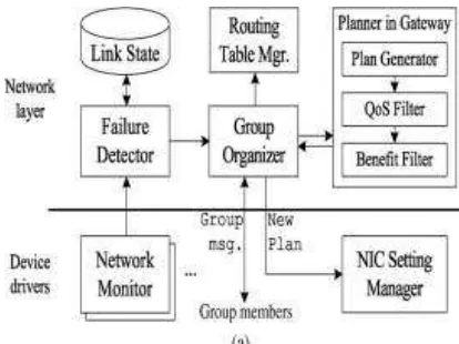
3.PROPOSED WORK: A. Ars Architecture
[image:3.595.303.510.416.571.2]Firstly we, present the design rationale and overall algorithm of ARS. Then, we detail ARS’s reconfiguration algorithms. Finally, we discuss the complexity of ARS
Figure 1: ARS Architecture For The Node
B. Overview
Figure 2: . Ars Reconfiguration Planning Method
I.Localized reconfiguration:
Based on multiple channels andradio associations available, ARS generates reconfigure town plans that allow for changes of network configurations only in the vicinity where link failures occurred while retuning configurations in areas remote from failure locations
Ii.Quiz-aware planning:
ARS effectively identifies Qos-satisfiable reconfiguration plans by: 1) estimating the QoS-satisfiability of generating reconfiguration plans; and 2) derevving their their expected benefits in channel utilization
Iii.Autonomous reconfiguration via link-quality monitoring:
ARS accurately monitors the quality of links of each node in a distributed manner. Based on the measurements and given links’ Qos constraints, ARS detect local link failures and autonomously initiates network reconfiguration
Iv.Cross-layer interaction:
ARS actively interact across thenetwork and link layers for planning. This interaction enables ARS to include a rerouting for reconfiguration planning in addition to link layer reconfiguration. ARS can also maintain connectivity during the recovery period with the help of a routing protocol
C. Planning For Localized Network Reconfiguration
The core function of ARS is to systematicallygenerate localized reconfiguration plans. A reconfiguration plan is defined as a set of links’ configuration changes (e.g., channel switch, link association) necessary for a network to recover from a link(s) failure on a channel, and there are usually multiple reconfiguration plans for each link failure[4]. Existing channel assignment and scheduling algorithms seek “optimal” solutions by considering tight Qos constraints on all links, thus requiring a large configuration space to be searched and hence making the planning often an np-complete problem . In addition, change in a link’s
requirement may lead to different network configurations completed. By contrast, ARS systematically generates reconfiguration plans that localize network changes by dividing the reconfiguration planning into three processes feasibility, Qos satisfiability, and optimality and applying different levels of constraints[10-12] As depicted in Figure. 3, ARS first applies connectivity constraints to generate a set of feasible reconfiguration plans that enumerate feasible channel, link, and route changes around the faulty areas, given connectivity and link-failure constraints. Then, within the set, ARS applies strict constraints (i.e., Qos and network utilization) to identify a reconfiguration plan that satisfies the Qos demands and that improves network utilization most.
D. Model Design Of Proposed Work:
Figure 3:ARS With AOMDV Protocol Implementation With Acknowledgement In Separate Path:
[image:4.595.318.514.346.479.2]
AOMDV has better performance and in some cases AODV has better performance.
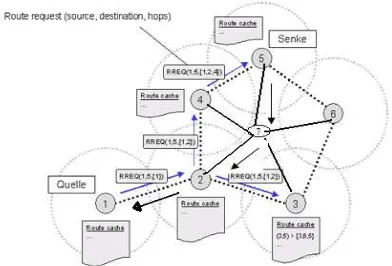
E. Steps To Implementation Of Aomdv: Algorithm:
STEP1:S is the source node selected and R1, R2 and R3 are the receivers.
STEP2: Multiple paths are selected using Dijikstras algorithm.
STEP3: Source node broadcasts the route request in multipath to the destination receivers R1, R2, R3 through the intermediate nodes
STEP4: RREQ reaches all the intermediate nodes. If the node recognizes a reliable path requested destination, it replies to the source node with a RREP message.
STEP5: If that particular node is not the destination, then it checks whether there is any valid path available for the destination. If it exists, it forwards the RREQ message to that node.
STEP6: After forwarding RREQ to the destination, the node appends its own address to a list of traversed hops and broadcasts the updated RREQ.
STEP7: Thus after getting the RREP message from that node, the specified path is available for the transmission. If the source node receives the RERR message, that path will not be used for the data transmission.
STEP8: In Multipath data transmission, QoS parameters for each path is calculated and the path which has got the highest QoS will be used for transmission.
STEP9: Redundant paths are identified and suitable path is randomly selected.
F.Aomdv Protocols:
The key distinguishing feature of AOMDV over AODV is that it provides multiple paths to nd[5].
These paths are loop free and mutually link disjoint. AOMDV uses the notion of advertized hop count to maintain multiple paths with the same destination sequence number. In both AODV and AOMDV, receipt of a RREQ initiates a node route table entry in preparation for receipt of a returning RREP[15]. In AODV, the routing table entry contains the fields:
<Destination IP address,
Destination sequence number, next-hop IP address,
Hop-count,
Entry expiration time>,
Where entry expiration time gives the time after which, if a corresponding RREP has not been received, the entry is discarded. In AOMDV, the
routing table entry is slightly modified to allow for maintenance of multiple entries and multiple loop free paths. First, advertized hop count replaces hop count and advertized hop count is the maximum over all paths from the current node to nd, so
only one value is advertised from that node for a given destination sequence number. Next hop IP address is replaced by a list of all nexthop nodes and corresponding hop-counts of the saved paths to nd from that node, as follows:
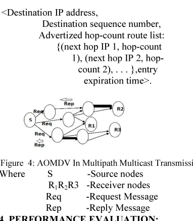
<Destination IP address,
Destination sequence number, Advertized hop-count route list:
{(next hop IP 1, hop-count 1), (next hop IP 2, hop-count 2), . . . },entry
[image:5.595.306.497.288.506.2]expiration time>.
Figure 4: AOMDV In Multipath Multicast Transmission Where S -Source nodes
R1R2R3 -Receiver nodes
Req -Request Message Rep -Reply Message
4. PERFORMANCE EVALUATION: A. Performance Metrics:
Ad hoc networks are designed to be scalable. As the network grows, various routing protocols perform differently. Some important measures of the scalability of the protocols are,
i.System life time ii.Network life time iii.Packet Delivery Ratio iv.End to End Delay
I. System life time:
System life time is defined as how long the system will perform with the efficient data transmission and reception and also its function depends on the delivery ratio and delay nodes.
II.Network life time:
The network lifetime depends on node and link quality.If the network cause the link[8-9] and node failure the total network lifetime will be reduced.
III. Packet delivery ratio
of total number of packets that have reached the destination node to the total number of packets originated at the source node.
IV. End-to-end delay
The packet end-to-end delay is the average time in order to traverse the packet inside the network. This includes the time for generating the packet from the sender up to the reception of the packet by receiver or destination and it is expressed in seconds. This includes over all delay of networks including buffer queues, transmission time and induced delay due to routing activities[13-14]. Different application needs different packet delay level.
5. SIMULATION RESULTS AND ANALYSIS:
The simulations were performed using Network Simulator 2 (Ns-2), particularly popular in the ad hoc networking community. The mobility model used is a Random Way point model. The traffic sources are CBR (continuous bit –rate), number of data connections is 10, data packet size is 512 bytes and data sending rate is 4 packets/second. The source destination pairs are spread randomly over the network in a rectangular field of 1000m x 1000m. During the simulation, each node starts its journey from a random spot to a randomly chosen destination. When the destination is reached, the node takes a rest period in seconds and another random destination is chosen after that pause time. This process repeats throughout the simulation, causing continuous changes in the topology of the underlying network. The simulation time is 500 seconds and maximum speed of nodes is 20 m/s. The primary energy of all nodes is 40 J. The interface queue is 50- packet drop tail priority queue. The following three simulations were conducted to evaluate the performance of the AODV and AOMDV protocol under varying conditions:
simulation1:varing number of nodes. simulation2:varying transmission rate. simulation3: varying pause time
Simulation 1
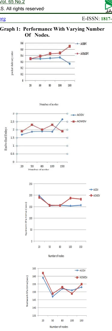
Graph1 shows the four performance metrics as a function of node numbers. In this simulation number of nodes considered 20, 50, 80, 100 and 150, pause time considered 80 seconds and transmission rate considered 10 packets/seconds.
[image:6.595.305.492.84.635.2]
Graph 1: Performance With Varying Number Of Nodes.
This table 1 describes Pause time=80sec,Transmission ratio=10 packets per secs and thus the comparison of AODV with AOMDV by varying number of nodes, the packet delivery ratio is increased to 50%,better end to end delay of 20%,network lifetime is 100% and system lifetime of 85.7%
Simulation 2
Graph 2 shows the four performance metrics as a function of node numbers. In this simulation transmission considered 5, 10 and 15 packets/seconds, number of nodes considered 70, pause time considered 80 seconds
Graph 2: Performance With Varying Transmission Rate
Number
of nodes
Packet delivery ratio End to end delay(sec)
protocol AODV AOMDV AODV AOMDV
20 0.35 0.35 1.7 1.9
50 0.35 0.39 1.88 2.3
80 0.36 0.43 1.9 2
100 0.37 0.44 1.88 2.3
150 0.27 0.55 2.65 1.9
Number
of nodes
Network life time(sec) System life time(sec)
protocol AODV AOMDV AODV AOMDV
20 159 162 199 191
50 147 149 155 157
80 152 153 157 156
100 151 149 154 188
150 153 155 157 183
Transmis
sion rate
[packets
per secs]
Network life
time(sec)
System life
time(sec)
AOD
V
AOMD
V
AOD
V
AOMD
V
5 174 179 179 185
10 150 147 159 153
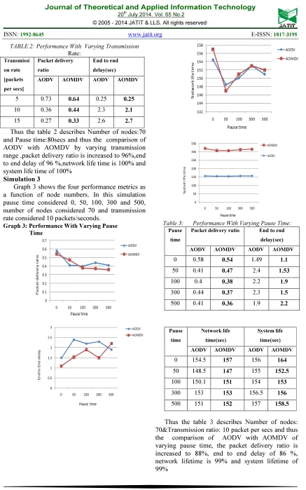
[image:7.595.71.517.76.765.2]TABLE 2: Performance With Varying Transmission
Rate:
Transmissi
on rate
[packets
per secs]
Packet delivery
ratio
End to end
delay(sec)
AODV AOMDV AODV AOMDV
5 0.73 0.64 0.25 0.25
10 0.36 0.44 2.3 2.1
15 0.27 0.33 2.6 2.7
Thus the table 2 describes Number of nodes:70 and Pause time:80secs and thus the comparison of AODV with AOMDV by varying transmission range ,packet delivery ratio is increased to 96%,end to end delay of 96 %,network life time is 100% and system life time of 100%
Simulation 3
Graph 3 shows the four performance metrics as a function of node numbers. In this simulation pause time considered 0, 50, 100, 300 and 500, number of nodes considered 70 and transmission rate considered 10 packets/seconds.
Graph 3: Performance With Varying Pause Time
Table 3: Performance With Varying Pause Time: Pause
time
Packet delivery ratio End to end
delay(sec)
AODV AOMDV AODV AOMDV
0 0.58 0.54 1.49 1.1
50 0.41 0.47 2.4 1.53
100 0.4 0.38 2.2 1.9
300 0.44 0.37 2.3 1.5
500 0.41 0.36 1.9 2.2
Pause
time
Network life
time(sec)
System life
time(sec)
AODV AOMDV AODV AOMDV
0 154.5 157 156 164
50 148.5 147 155 152.5
100 150.1 151 154 153
300 153 153 156.5 156
500 151 152 157 158.5
6. CONCLUSION:
This research work evaluated the performances of ARS with the protocols AODV and AOMDV using NS-2 simulator. An autonomous network reconfiguration system (ARS) that enables a multimedia wireless network to autonomously recover from wireless link failures. ARS generates an effective reconfiguration plan that requires only local network configuration changes by exploiting channel, radio, and path diversity. Furthermore, ARS effectively identifies reconfiguration plans that satisfy applications’ QoS constraints, admitting up to two times more flows than static assignment, through QoS-aware planning. Next, ARS’s online reconfigurability allows for real time failure detection and network reconfiguration through the acknowledgement process, thus improving channel efficiency by 92%. Our experimental evaluation on ns2-based simulations have demonstrated the effectiveness of ARS in recovering from local link failures and in satisfying applications’ diverse QoS demands. The comparison was based on of packet delivery ratio, network life time and system lifetime and end-to-end delay. Simulation results are shown by the figures. In a first simulation number of nodes is varied, but pause time and transmission rate are fixed. In the second simulation transmission rate is variable, but the number of nodes and pause time are fixed. In the third simulation pause time is variable, but the number of nodes and transmission rate are fixed.
7. FUTURE WORKS:
In wireless networks, many types of protocols are available. Here we are proposed only AOMDV protocol with ARS algorithm. Channel aware AOMDV and Energy efficient AOMDV are the latest evolution of AOMDV protocol types. These protocols are having better performance than the AOMDV. By using these type of protocols we will address in a forthcoming paper.
REFERENCES:
[1] I. Akyildiz, X. Wang, and W. Wang, “Wireless mesh networks: A survey,” Comput. Netw., vol. 47, no. 4, pp. 445–487, Mar. 2005.
[2] “MIT Roofnet,” [Online]. Available: http://www.pdos.lcs.mit.edu/ roofnet
[3] Motorola, Inc., “Motorola, Inc., mesh broadband,” Schaumburg, IL [Online]. Available: http://www.motorola.com/mesh [4] P. Kyasanur and N. Vaidya, “Capacity of
multichannel wireless networks: Impact of number of channels and interfaces,” in Proc.
ACMMobiCom, Cologne, Germany, Aug. 2005,
pp. 43–57.
[5] K. Ramanchandran, E. Belding-Royer, and M. Buddhikot, “Inter-ference-aware channel assignment in multi-radio wireless mesh networks,” in Proc. IEEE INFOCOM, Barcelona, Spain, Apr. 2006,
pp. 1–12.
[6] . Draves, J. Padhye, and B. Zill, “Routing in multi-radio, multi-hop wireless mesh networks,” in Proc. ACM MobiCom, Philadelphia, PA, Sep. 2004, pp. 114–128.
[7] P. Bahl, R. Chandra, and J. Dunagan, “SSCH: Slotted seeded channel hopping for capacity improvement in IEEE 802.11 ad-hoc wireless networks,” in Proc. ACM MobiCom, Philadelphia, PA, Sep. 2004, pp. 216–230. [8] Aguayo, J. Bicket, S. Biswas, G. Judd, and R.
Morris, “Link-level measurements from an 802.11b mesh network,” in Proc. ACM SIG-COMM, Portland, OR, Aug. 2004, pp. 121–132. [9] A. Akella, G. Judd, S. Seshan, and P. Steenkiste, “Self-management in chaotic wireless deployments,” in Proc. ACM MobiCom, Cologne, Germany, Sep. 2005, pp. 185–199.
[10]J. Zhao, H. Zheng, and G.-H. Yang, “Distributed coordination in dy-namic spectrum allocation networks,” in Proc. IEEE DySPAN, Balti-more, MD, Nov. 2005, pp. 259–268. [11]M. J. Marcus, “Real time spectrum markets
and interruptible spectrum: New concepts of spectrum use enabled by cognitive radio,” in
Proc.IEEE DySPAN, Baltimore, MD, Nov.
2005, pp. 512–517.
[12][12] M. Alicherry, R. Bhatia, and L. Li, “Joint channel assignment and routing for throughput optimization in multi-radio wireless mesh networks,” in Proc. ACM MobiCom, Cologne, Germany, Aug. 2005, 58–72.
[13] Xiaoqin chen, H.M.Jones, D.Jayalath
“Channel Aware Routing inMANETs with route handoff” IEEE transactions on mobile computing, Vol.10,No.1, January 2011.
[14] C.-K. Toh "Maximum battery life routing
to support ubiquitous mobilecomputing in wireless ad hoc net-works", in IEEE Communication Magazine,June 2001.
[15] P. Bergamo A. Giovanardi, et al,