ABSTRACT
CASE, GARY NORMAN. Design, Function and Biological Applications of
Stereoscopic Display Technology. (Under the direction of Dr. John M. Mackenzie, Jr.) The purpose of the research is to examine if advances in computer technology would facilitate the adoption of stereoscopic display systems. We examined and evaluated a variety of computer-based stereoscopic display technologies. We developed a stereoscopic image acquisition and projection system for use with a stereomicroscope. The projection system can also be used in conjunction with a set of stand-alone stereo cameras for more lifelike
DESIGN, FUNCTION AND BIOLOGICAL APPLICATIONS OF STEREOSCOPIC DISPLAY TECHNOLOGY
by
GARY NORMAN CASE
A thesis submitted to the Graduate Faculty of North Carolina State University
in partial fulfillment of the requirements for the Degree of
Master of Science
MICROBIOLOGY
Raleigh 2003
APPROVED BY:
________________________________ ________________________________ Dr. Dennis T. Brown Dr. Geraldine Luginbuhl
BIOGRAPHY
Gary Case was born in Durham, North Carolina in April of 1975. He received a B.S. degree in Biology from Tennessee Technological University in May of 1997. In August of 1997, he began graduate school in the Microbiology department of North Carolina State University.
TABLE OF CONTENTS
Page
LIST OF TABLES v
LIST OF FIGURES vi
PREMISE 1 BACKGROUND AND REVIEW
Principles of stereo vision 2
Acquisition of stereo images in biological systems 3
Stereomicroscopy 4
Confocal microscopy 5
Scanning electron microscopy 6
Transmission electron microscopy 7
History of stereoscopic display 8
Anaglyphic stereo 10
Evolution of stereoscopes 11
Stereoscopic projection 13
Computer based display 14
Shuttered displays 14
Polarizing displays 19
Autostereoscopic displays 21
Single projector system 22
Image alignment 23
EXPERIMENTS AND RESULTS
Microscope system 25
Projectors and stands 30
Dual video cameras 35
Alignment protocol 37
Remote applications using the network 41
CONCLUSIONS 51
REFERENCES 54
APPENDICES
A. Microscope alignment protocol 58
B. Projection system alignment protocol 64
C. Camera alignment protocol 68
D. A Quick Guide to CAMVision-2 Setup and Operation 70 E. COM port configuration for remote control application 76
F. Remote control solutions for JSM 5900LV 77
LIST OF TABLES
Page
1. Bandwidth requirements 50
LIST OF FIGURES
Page BACKGROUND AND REVIEW
1. Stereomicroscope stereopair of a butterfly wing 4 2. Confocal stereopair of rhabdomeres and pigment cells in the
developing fruit fly eye (from Goodhouse) 6
3. SEM stereopair showing dissected flower structure of a carnivorous plant (J. M. Mackenzie, unpublished)
7 4. Sindbis virus stereopair from reconstruction by single-particle
method (from Paredes, et al.) 8
5. Wheatstone’s first stereoscope (from Wheatstone 1) 9 6. Two of Charles Wheatstone’s original hand-drawn stereo images
(From Wheatstone 1)
10
7. Holmes-type stereoscope (from Greenslade) 11
8. Modern fixed-size stereoviewers 12
9. Wild stereoviewer 12
10. Modern View-Master viewing device with reels 13
11. Custom-built active shutter goggles 16
12. NuVision 3-D SPEX 17
13. NuVision 60GX goggles 18
14. NuVision 17SX LCD shutter panel on 17” Sony monitor 19 15. Paper glasses used in conjunction with NuVision 17SX screen 20 16. 3D PIX editing software from NuVision (MacNaughton) 24
EXPERIMENTS AND RESULTS
17. Leica MZ12 stereomicroscope fitted with Kodak MDS120 capture system
26 18. Camera tube modifications (note the shortened lever and notched
slider in the right hand image)
27 19. African violet stereopair from MDS120 system 28 20. Stereomicroscope with dual stereo video cameras 29
21. Portable televisions 30
22. Local stereo projection system 31
23. Second generation stand with Kodak DP850 Ultra projectors 33
24. Third generation stand with Kodak DP1050 Ultra projectors 34
25. Canon document cameras 35
26. Sony DCR-PC1 cameras 36
27. Optical axis diagram of projection display systems 39 28. Real-time stereo projection over an ATM network 42 29. CAMVision-2 encoders located at the imaging end of the system 43 30. CAMVision-2 dual-decoder box that travels to the display site 44
31. Real-time stereo projection over Internet2 45
32. Stereomicroscope, preview monitor and controlling computer system in use during a demonstration
47
33. Remote control software interface 48
CONCLUSION
34. Real-time remote control of SEM using modules 52
PREMISE
BACKGROUND AND REVIEW
Principles of stereo vision
Humans exist in a three-dimensional world. The ability to perceive depth and distance is an important part of our daily lives. We interpret a number of visual cues to extract depth information from our surroundings in a process known as stereoscopic vision. Some of these cues can be perceived using only one eye, and are called monocular cues. Others require two eyes to be seen, and are therefore called binocular cues (Howard, Rogers).
The monocular cues are:
1. Perspective – The change in the size of an object as its distance from the observer changes.
2. Overlap – If an opaque object is placed in front of a second object, part of all of the second object will be blocked from view
3. Lighting – Differences in shading, shadows cast by objects and reflections of light off of objects give the viewer clues to the distance, depth, and shape of objects
4. Focusing – Depending on the differences in depths of a series of objects, the eye may need to refocus when looking from object to object
5. Motion parallax – When observing a series of objects while either the observer or the objects are in motion, the relative motion of the objects is related to the distances of the objects from the viewer.
The binocular cues are:
1. Vergence – The change in position (convergence or divergence) of the eyes required to fixate on objects at different depths
2. Binocular disparity – differences in the image captured by each eye when observing an object due to the spacing of the eyes
(after Howard, Rogers)(Livingstone)
To better illustrate our interpretation of these visual cues, imagine this scenario. It is early morning and you are sitting at your kitchen table, eating a bowl of cereal. Because it’s still dark outside you have the light on above the table. You’ve put your spoon into the bowl, scooped up a spoonful of cereal and have begun to lift the spoon out of the bowl towards
your mouth. When your spoon is just leaving the cereal bowl, both the surface of the bowl and spoon are in focus at the same time (focus, vergence). The spoon is blocking part of the surface of the bowl, and the milk and cereal are blocking your view of the surface of the spoon (overlap). If you were to hold the spoon at that location, and alternately close your left eye and right eye, you would see slight differences in the two images of the bowl and spoon (binocular disparity). Moving your head slightly from side to side would cause both the spoon and the bowl to move, but with no real discernable difference in the amount of movement of the bowl and the spoon (motion parallax). If you follow the spoon with your eyes as you move it to the halfway point between the bowl and your mouth, your eyes will refocus and converge to adjust for the change in distance as the spoon moves (focus,
vergence). Because the spoon is now closer to your eyes, it appears larger than it did when it was at the cereal bowl (perspective). If you stop the spoon at this halfway point while
keeping your eyes focused on the spoon, you would see that the cereal bowl in the background is no longer in focus, and in fact appears as two separate images (focus,
vergence). If you alternately closed your eyes again, there would be slight differences in the images of the spoon, but much larger differences in the position of the cereal bowl; it would appear to jump around as you closed and opened your eyes (binocular disparity, vergence). If you then shift your focus from the spoon to the cereal bowl, your eyes would diverge and refocus on the bowl, which would cause the spoon to become blurry and split into two images (focus, vergence). Moving your head from side to side again would make the spoon and bowl appear to move at different rates, as the spoon is nearer to you (motion parallax). Your arm and the spoon cast a shadow on the bowl and the table, as they block the light from above the table (lighting). Now that you’ve observed all the major depth cues, finish eating your cereal and proceed on to the next section. In it we will discuss sources of
three-dimensional data in the scientific community.
Acquisition of stereoscopic images in biological systems
There are many different imaging techniques used in science that generate stereoscopic data. For this data to be useful, it needs to be captured in a form that can be manipulated for presentation. The presentation method will depend on the group for which the data is being prepared. In this section I will describe several instruments that generate
stereoscopic images, concentrating on those most useful in biology, and provide some example images. These images are presented as stereoscopic display pairs arranged for viewing with the crossed-eye method. To perceive the stereoscopic effect, the viewer must cross his or her eyes until the two images contained within the stereopair fuse into one. Here is a partial list of instruments that can produce stereoscopic images:
1. Stereomicroscope 2. Confocal microscope
3. Scanning electron microscope 4. Transmission electron microscope
Stereomicroscopy
A stereomicroscope can be thought of as two compound microscopes arranged side by side. The slight offset between the two optical systems mimics the offset in the human vision system, allowing the microscope to generate three-dimensional images (fig. 1). This type of microscope does not generate high magnification. Stereomicroscopes are usually fitted with a variable zoom system to adjust the level of magnification rather than using a set of interchangeable objective lenses. Stereomicroscopes are used to observe larger whole specimens like insects or plants, and when performing dissection or surgery of smaller objects.
Figure 1. Stereomicroscope stereopair of a butterfly wing
There are two basic designs for stereomicroscopes; the Greenough and common main objective (CMO) types. The microscope used in this study was of the CMO type. It is
distinguished from the Greenough-type microscope by having only one objective lens that is shared by two optical systems. The Greenough microscope has two complete, separate objective lenses (Zeiss). Stereomicroscopes based on the CMO principle are usually designed to be modular, with many attachments available for use. For example, most
stereomicroscopes can be fitted with a phototube and camera to document specimen observations. To photograph a specimen, light is diverted inside the microscope so that it passes out a phototube instead of one of the eyepieces. A focusing adapter between the phototube and camera focuses the image on the CCD sensor or film inside the camera. Photographing a stereopair on our standard stereomicroscope is more complicated than capturing a two-dimensional image. After photographing the left image of the stereopair, the observer would have to disassemble and reassemble the microscope, moving the phototube, focusing adapter and camera to the right side before he or she could photograph the right image. It is striking that most stereomicroscopes do not have the ability to mount two cameras as this would greatly simplify the process of capturing stereoscopic images.
Confocal microscopy
A different type of microscopy that generates three-dimensional data is confocal laser scanning microscopy (CLSM). The term confocal, meaning “at the same focus”, is used to describe this type of microscope because the area of the specimen on which the light is focused is the same area of the specimen on which the detector is focused (Bio-Rad). The detector only captures in-focus light. A pinhole called the confocal aperture is placed at the point of focus before the detector. This blocks any out of focus light, greatly increasing contrast and sharpness as light from out of focus regions of the specimen which would normally cause blurring is blocked. It also makes possible the ability to non-invasively optically section a specimen. Because the illumination source is focused to a single point, either the specimen or the point of illumination must be moved (scanned) to generate a complete image.
CLSM is often used by biologists to perform fluorescence microscopy. In
fluorescence microscopy, a light source interacts with a naturally occurring or experimentally introduced fluorescent substance in the specimen, causing it to emit light. It is this emitted light that is captured by the detector in the CLSM. The illuminating light is blocked from the
detector through the use of a dichroic mirror, and out of focus light is rejected by the pinhole system, so only in-focus light from the fluorescing specimen is recorded.
By optical sectioning, a three-dimensional model of a specimen can be created in a non-destructive manner. After completing an XY scan at one level, the system is refocused at a higher or lower Z level in the specimen and another XY scan is taken. When a number of these “slices” have been created, they are processed by a computer which reconstructs them into a three-dimensional model. This model can be manipulated in the computer to view the specimen from all angles (Sheppard and Shotton). Further processing by the computer can create two views at different angles. These two views become a stereoscopic display pair (fig. 2).
Figure 2. Confocal stereopair of rhabdomeres and pigment cells in the developing fruit fly eye (from Goodhouse)
Scanning electron microscopy
Scanning electron microscopy (SEM) uses a focused beam of electrons to create an image of the surface of a specimen. Like confocal microscopy, it scans the beam across the specimen and obtains data from one point at a time.
Stereopairs of samples in the SEM can be created by taking one image of a specimen, tilting the specimen stage and then taking a second picture (JEOL). An example stereopair of an SEM sample can be seen in Figure 3. The stage is usually tilted from 3 to 6 degrees
depending on the degree of stereo separation desired. The different tilts approximate the spacing of human eyes and are therefore dependent on magnification.
Figure 3. SEM stereopair showing dissected flower structure of a carnivorous plant (J. M. Mackenzie, unpublished)
Transmission electron microscopy
A stereoscopic TEM image can be generated in several different ways. The simplest method is to tilt the specimen and take two pictures as described previously for the SEM (Bozzola, Russell). Because samples viewed in a TEM are extremely thin, often there is not much depth revealed by creating a stereoscopic image using this technique.
Serial sectioning can be used to create a three-dimensional model of a specimen. The specimen is sectioned using an ultramicrotome and photographs of each section are taken. The images of the specimen are then arranged in order and a model of the specimen can be reconstructed. This method provides detailed information about the structure of the
specimen, but it is very time consuming and difficult to perform.
Tomography is another method for creating a three-dimensional model of a specimen. In tomography, a three-dimensional model of an object is reconstructed from a tilt series. To obtain these images, a specimen is tilted along a single axis. Images of the specimen are captured at regular intervals along the tilt. These projected images are processed in Fourier space using a computer. The computer calculates the backprojection body of each projection image, and when these values are added together, a model of the densities in the original
object is created (Baumeister et al.). Biological specimens are often prepared at cryogenic temperatures to avoid damage during image capture.
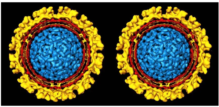
A fourth method commonly used for three-dimensional reconstruction is called particle reconstruction. Instead of using many photographs of one object, single-particle reconstruction is performed with images containing many randomly oriented copies of the same object. Figure 4 is a reconstruction of Sindbis virus that was prepared using this method (Paredes, et al.). This method avoids the lengthy exposure to the beam that any tilt series requires (Frank, Radermacher).
Figure 4. Sindbis virus stereopair from reconstruction by single-particle method (from Paredes, et al.)
History of stereoscopic display
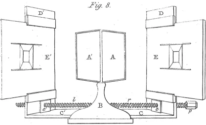
Although stereoscopic imaging is not in widespread use today, it has a long history. In fact, stereoscopic imaging predates photography. Systems for the creation and viewing of stereoimages have existed since the 1830s. In 1832, Sir Charles Wheatstone developed the first stereoscope (fig. 5) (Bowers). It was Wheatstone who named the instrument, from the Latin stereo, meaning “solid” and scop- which means “to see” (Howard, Rogers).
Figure 5. Wheatstone’s first stereoscope (from Wheatstone 1)
It was a mirror-based instrument, designed to present dissimilar images to the eyes while ensuring each eye only saw the picture intended for it. At the center of the device were two mirrors, mounted in a triangular fashion with their backs at a 90° angle. Facing these central mirrors were movable vertical boards mounted on a screw. When the screw was turned, the boards would move closer to or further from the mirrors. On these boards Wheatstone would place specially prepared drawings. Observers would sit in front of the stereoscope as close as possible to the mirrors while looking straight ahead. When the boards were moved to such a position that the images they held were centered in the mirrors, a three-dimensional object created by the fusion of the images seen in the left and right mirrors could be seen
(Wheatstone 1). Wheatstone’s reason for building the instrument was to investigate the effects of the small differences seen in the images perceived by the left and right eye when looking at an object. Through his experiments, Wheatstone was the first to discover that these differences conveyed not just a sense of the depth relationships of groups of objects, but actual depth in the structure of an individual object (Bowers).
Figure 6. Two of Charles Wheatstone’s original hand-drawn stereo images (From Wheatstone 1)
Several years after Wheatstone’s paper describing his experiments with hand-drawn stereopairs (fig. 6) was published, photography was invented. Wheatstone began
experimenting with stereophotographs. He determined the best method for capturing stereoimages was to use two cameras simultaneously. He further determined the proper alignment for the cameras to convey the correct amount of depth (Wheatstone 2). Another prominent scientist of the day, Sir David Brewster, developed a lens-based stereoscope shortly after Wheatstone (Wade).
Anaglyphic stereo
The stereoscope previously described relied on total separation of the two viewed images. In 1853, Rollmann developed a new method of stereo display. He drew figures on a white chart using red and blue colored lines. Viewers were given glasses with red and blue lenses. When looking at the drawing, the red lines could not be seen by the eye that looked through the red lens, and the blue lines could not be seen by the eye that looked through the blue lens. The brain therefore perceived two different images which it assembled into a three-dimensional object. This is called anaglyphic stereo, and it uses color to encode / decode the left and right images from within a single image (von Helmholtz).
In 1858, Joseph D'Almeida exhibited the first projection anaglyphic photographs (von Helmholtz). In 1891, the anaglyph method of stereoscopic presentation was patented by Louis Ducos du Hauron, a pioneer in early color photography and color systems.
(Britannica). Because they are simple to reproduce using modern printing or photographic techniques, anaglyphs can be printed in books or reproduced in projection slides, giving scientists an inexpensive way to share stereoscopic images. However, one of the major
drawbacks of the anaglyphic process is that it is best suited for monochromatic (black and white) images and not color images.
Evolution of stereoscopes
The simplest method for stereoscopic viewing is crossed-eye viewing. In this system, the pair of views of an image is placed side by side, with the image intended for the right eye on the left, and the image for the left eye on the right (Klein). When the viewer crosses his or her eyes, the images merge to produce a stereoscopic image. Because this method only works for a limited number of individuals, a series of stereoscopes was invented to facilitate
viewing of stereopairs.
A stereoscope created by Oliver Wendell Holmes was very popular in the late 19th century. This device uses lenses to allow the viewer to perceive a stereoscopic effect from a pair of images mounted side by side on a card (fig. 7). A long piece of wood placed between the lenses enhances the separation of the left and right images.
Figure 7. Holmes-type stereoscope (from Greenslade)
A similar type of side-by-side image viewer can be seen in Figure 8a and b. These simple modern viewers require a small, fixed spaced pair of images.
Figure 8. Modern fixed-size stereoviewers
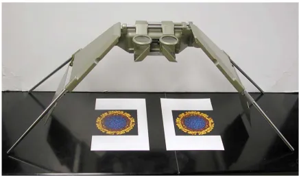
A much more versatile system is available to view stereo pairs. Designed originally for aerial photography, the Wild Stereoviewer (fig. 9) is a device that uses lenses and two sets of front-surface mirrors to create the stereo effect from a stereopair. To view the images in stereo, two separate photographs are placed under the stereoviewer and aligned manually. This system’s high quality optics and extensive adjustability produces an extremely high quality stereo view.
Figure 9. Wild stereoviewer
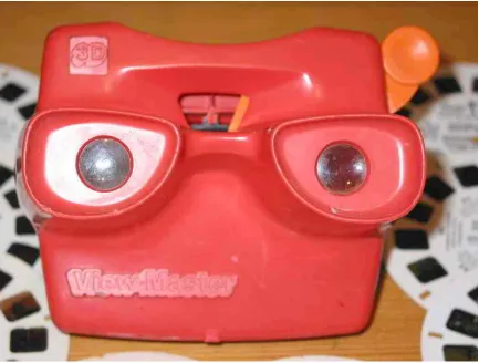
The most popular stereoscopic viewing system still in use today is the View-Master system (fig. 10). This system first went on sale in 1939 and has always been marketed as an entertainment device. The system consists of a viewing device and a reel containing seven stereoscopic images. The images are stored on the reel as stereopairs. The View-Master uses two optical paths to create the stereo effect (Baird). The View-Master is the most
commercially successful stereoscopic display system.
Figure 10. Modern View-Master viewing device with reels
Stereoscopic projection
The methods described so far are limited to single person viewing. If a larger audience is to view the stereo effect, different methods are necessary. A standard 2x2 slide projector can be used to create slides that appear to be three-dimensional using the red / blue anaglyph system previously described.
Stereoscopic viewing can also be done using two slide projectors and polarized light. Light can be polarized in one direction by a polarizing filter. If a second polarizer is placed at
90° to the first the polarized light is blocked by this filter. If the left projector has a polarizer whose vector is up and down and the right has a filter whose vector is left and right, a pair of glasses with the vectors parallel to the projectors would allow the image from only one projector to be seen by each eye.
The most common type of projection screen amplifies the brightness of the projected image by scattering light. Scattering depolarizes light, so the use of a standard projection screen with a polarized light stereoscopic display system would ruin the stereoscopic effect. A special silver lenticular screen can be purchased that does not depolarize the light but does amplify somewhat the projected image.
When using a two-projector system, the alignment of the projectors becomes critical. Simply aligning two slide projectors is a difficult task. There must be large tolerances in the loading mechanism of the slide projectors in order to accommodate a large variety of slides and slide holders. These tolerances become misalignments when subsequent slides of a stereopair are viewed. Complex holders and custom projectors were never successful in making this system routine. It appears relatively easy to create a stereo effect, but very difficult to create a good, stable stereo effect for a large number of slides due to these alignment problems.
Computer-based display
The modern digital computer should facilitate stereoscopic display because of the fast, high resolution display and because of its ability to manipulate image data for precise alignment. All stereoscopic display systems whether historical or modern perform the same tasks. Each device must deliver the proper view to the correct eye. The computer can be used to deliver separate images in two major ways. One is by shuttering, the other is by
polarization.
Shuttered Displays
One way to deliver stereoscopic images would be to alternately display the right and left images of a stereopair on the same viewer while a shutter device allows the left eye to see only the left image and lets the right eye only see the right image. Since the image is
displayed on a single device, the images would only have to be aligned once. This shuttering
device would need to be synchronized with the display of the left and right images. If the images are shuttered quickly enough, the brain would perceive the image as a stereoscopic picture.
During early research into television, it was discovered that when a series of images is displayed at 30 frames per second, the brain perceives the stream of images as continuous and flicker-free. To achieve 30 frames per second to each eye in a stereoscopic display system, the system would have to switch between images at 60 times per second. If the rate is slower than this, the viewer will perceive noticeable flicker. Some computer displays are capable of rapidly switching between two images at these rates.
The first computer-based stereoscopic systems were prohibitively expensive, as they used workstations from Silicon Graphics that cost tens of thousands of dollars. These systems also used proprietary shutter goggles manufactured by StereoGraphics to decode the
stereoscopic images. A similar system could be made by using far less expensive IBM-compatible computers. An IBM-IBM-compatible stereoscopic display system was constructed in order to create an affordable stereoscopic display system for scientists.
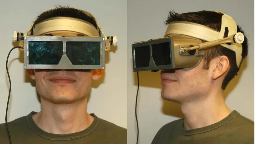
This system is made up of a monitor, computer, display software, and a device that selectively displays the correct image to each eye. The first shuttering device built in our lab was a pair of shutter goggles similar to the type of device used with the Silicon Graphics stereoscopic display system. Shutter goggles are devices worn in front of the eyes that can rapidly change from transparent to opaque. They are so named because they function like a camera shutter which opens and closes to admit or exclude light. Since this shuttering action is produced by a dynamic, electronic process they are called active shutter goggles (Johnson and Bos).
Figure 11. Custom-built active shutter goggles
The shuttering action of the goggles requires power and it must be synchronized to the change in images on the computer screen for the stereoscopic effect to work. The right lens must become opaque when the left image is displayed on the screen, and vice versa. This change must happen extremely rapidly, as the system must switch between images at greater than television rates. The lens portion of the goggles is from a set of shutter goggles designed by Tektronix for IMAX, a large format movie theater. These lenses are specifically designed to switch very quickly with a large viewable area.
The cable leading to these glasses, which can be seen in Figure 11, provides the glasses with power and carries a control signal from a custom built box that is connected to the computer. This cable is called a tether. A tethered system restricts the viewing distance and usually limits the number of users to one. The major difficulty however is that if the viewer inadvertently forgets that he is tethered to the system, the goggles will be pulled to the floor when he reaches the end of his “rope” (this was the fate of the original goggles).
In the days since this first experimental computer-based stereoscopic display system was developed, a few affordable commercial display systems have become available. In my experiments, I used two models of shutter goggles produced by NuVision, now
MacNaughton (Beaverton, OR). Both of these goggles use the same type of optical device as
the original custom built goggles. These systems are usually tied to a particular brand and model of display card and software.
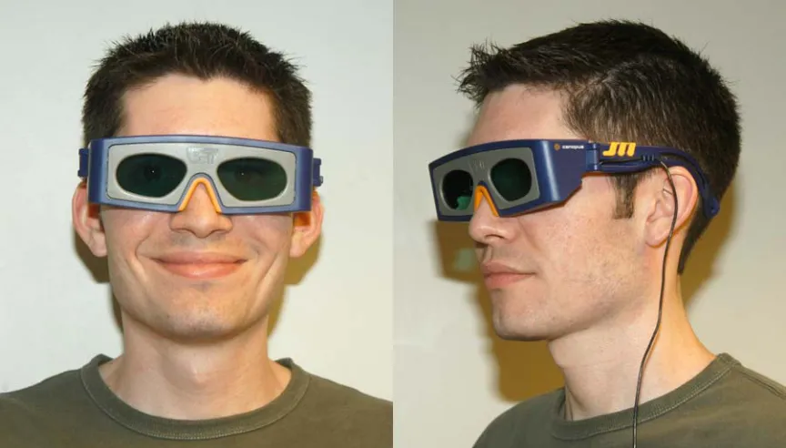
The first shutter goggles examined are a modern version of the tethered experimental goggles called 3-D SPEX (fig. 12). They are primarily designed for playing stereoscopic video games and are affordable with a list price of $99.
Figure 12. NuVision 3-D SPEX
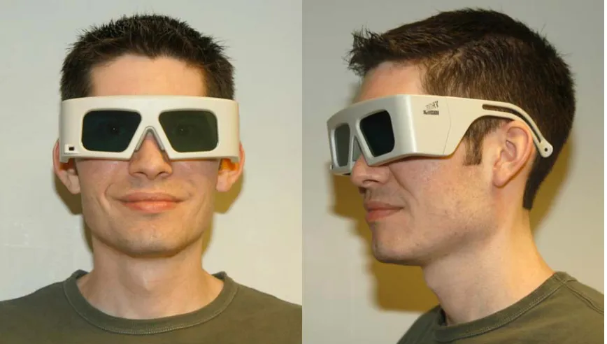
Figure 13. NuVision 60GX goggles
One of the best designs of modern shutter goggles is the 60GX goggles from NuVision (fig. 13). These goggles do not require a tether. They are powered by onboard batteries, are only active when unfolded, receive the synchronization signal over an infrared receiver and cease shuttering when no signal is present. A set of goggles with the infrared emitter that transmits the synchronization signal from the computer costs about $350. (Extra pairs of glasses are available for $200.)
Polarizing displays
Another system developed for displaying stereoscopic images on a computer uses a polarizing panel which fits over the front of a monitor screen, creating a polarized display monitor. The panel we used in our experiments is the NuVision 17SX 17” polarizing screen (fig. 14). It is used in conjunction with inexpensive paper glasses shown in Figure 15 (available from American Paper Optics at http://www.3dglassesonline.com) to perceive the stereoscopic effect.
Figure 14. NuVision 17SX LCD shutter panel on 17” Sony monitor
This panel uses a more elaborate system than those previously described. In order to explain how this system works, it is necessary to first discuss polarized light. Light behaves as either a wave or a particle. When studying the polarization of light, the wave model of behavior dominates. According to this model, light exists in waves that vibrate perpendicular to the direction of travel. If a wave of light were traveling toward you from this paper, the wave could vibrate up and down, side to side, and at all angles in between. The waves can
even trace a circular or elliptical pattern. Non-polarized light, such as the light from an ordinary desk lamp, actually consists of many polarization forms all at once. When this light passes through a device called a polarizing filter, light that is vibrating in one specific
direction is allowed to pass through with other vibration forms being blocked. Polarized light can be further modified by devices called retarders. Retarders modify the polarization state of the light emerging from the polarizing filter, either changing its form or the direction of polarization. Depending on the type of polarizing filter and retarder used, the light emitted can be linearly, elliptically or circularly polarized (circular polarization is a special case of elliptically polarized light). The combination of a linear polarizer and a properly oriented quarter-wave retarder is called a circular polarizer. Circularly polarized light is classified by the direction of its rotation, and is referred to as either left-handed or right-handed. (Shurcliff and Ballard)
Figure 15. Paper glasses used in conjunction with NuVision 17SX screen
In the polarizing frame attached to the monitor are a linear polarizer, a quarter-wave retarder and a pi-cell (Johnson). A pi-cell is a type of rapidly switching, variable light
retardation device tuned to introduce a half wavelength (180°) phase shift in light that passes through it (Bos and Koehler/Beran). It is called a pi-cell because when expressing the
wavelength of light in radians, pi is equal to 180°. When an electrical charge is applied to the
cell, the liquid crystal molecules within the cell align in such a way that light transmitted through the cell passes through unaffected. When the current is lowered to a holding voltage and the cell is allowed to relax, it introduces a half wavelength shift to transmitted light. A half wavelength phase shift rotates the polarization state of transmitted light by 90°.
Light from the monitor first passes through the linear polarizer. Next, the linearly polarized light passes through a quarter-wave retarder whose fast axis is 45° from the light’s polarization angle. Inside the retarder, one of the two beams of light undergoes a quarter wavelength (90°) phase shift with respect to the other beam. When the two beams are recombined upon emergence from the retarder, the light is converted from a linear to a circularly polarized form. When the circularly polarized light passes through the pi-cell, it is transmitted without change if the cell is active or the polarization state is shifted 180° if the cell is relaxed. For example, if the polarizer and retarder are arranged to produce
right-circularly polarized light, when the pi-cell is active the light passes through unchanged and is transmitted to the observer as right-circularly polarized light. If the cell is in a relaxed state, light is converted to left-circularly polarized light (Johnson). The system works due to the extremely fast rate at which the pi-cell can switch between states. The glasses deliver the proper image to the proper eye when the appropriate circularly polarizing filters are present. If switched quickly enough, the brain puts the two images together and perceives them as a stereoscopic image.
The polarizing screen has a switch that allows the viewer to change which image is seen by the right eye. The screen costs about $1700 and the paper glasses only cost $1 per pair.
Autostereoscopic displays
Some perceive viewing stereo with goggles as a problem. There have been many attempts to create a glasses-free display system, also called an autostereoscopic display. We purchased and tested the 2015XLS flat panel display from Dimension Technologies Inc. (Rochester, NY). It uses a standard transmissive 1024x768 pixel LCD panel coupled with a patented lighting system to encode stereoscopic images using what DTI calls “Parallax illumination”. Standard LCD computer monitors consist of an image-forming LCD panel and a backlight designed to illuminate the entire panel simultaneously. The DTI monitor adds a
second, non-image producing LCD panel between the image-forming panel and the backlight (Eichenlaub). When the system is in stereoscopic mode, the non-imaging LCD panel
becomes opaque in sections, creating 512 bright vertical columns of light behind the imaging LCD panel. When a user sits at a specific distance from the display, the user’s left eye sees these columns of light only through the odd columns of the image-producing LCD, and their right eye only sees the lights through the even columns of the LCD. By taking stereo pair images with 1024x768 pixel resolution and discarding alternate odd columns of pixels for the right image and even columns of pixels for the left, both images can be displayed on
alternating columns of the panel at the same time. The parallax illumination system attempts to restrict each eye to seeing only the image it is intended to see, so the user perceives a stereo image merely by looking at the display (DTI).
The stereo effect depends heavily on the positioning of the observer, because the separation depends on the user sitting in a specific, pre-determined location. The positioning requirements are so restrictive that it is extremely difficult to find the proper place for viewing and virtually impossible for the observer to find and maintain their head in that one place. Although the most expensive of the systems tested, it provided the least satisfactory stereo effect.
Single projector system
The monitor-based display systems described above would be impractical to use with larger groups of people. If a computer projector could alternate the display of the left and right images at television rates or higher, it should be possible to use shutter goggles to perceive a stereoscopic image on a projection screen. To test this theory an LCD-based computer projector was connected to a computer running the stereo display software for the shutter goggles and the projected image was viewed using these goggles. There was no acceptable stereoscopic effect due to a complete lack of synchronization. There appeared to be a synchronization mismatch between the input synchronization signal which was
generated by the goggle software and the output synchronization signal of the projector. When the goggles were synchronized to the output side, the synchronization would work for a limited period of time before the left and right images would swap. It was clear that the projector needed to drop frames at random in order to keep pace with the live VGA signal.
This would reverse the relationship between the shuttering of the goggles and the VGA display. Later, when we tested Kodak DLP-based computer projectors, we were successful in creating a single projector system both with the shuttered goggles and with the polarizing screen. This was because the input stream and output stream were in perfect synchronization. This type of projector is based on a DLP chip that allows for much faster frame rates, so it was not necessary to drop any frames to keep pace with VGA signal.
Image alignment
Modern and historic stereoscopic display systems both require properly aligned images in order to perceive the three-dimensional effect. The images for the left and right eyes must be closely matched in tonal qualities and differ only by viewing angle. In the rigid systems shown in Figures 7, 8 and 9, the images need only be aligned once and then turned into a fixed composite. In our modern systems, computers can be used to prepare the images for viewing, to align them, and to display them. We match the tonal properties of the images using programs like Adobe Photoshop and store the original and edited versions using the TIFF file format (uncompressed).
The images can be aligned for stereo viewing by a number of stereo editing programs. These programs are closely linked to the display hardware because the display card must be stereo-capable. To be stereo-capable, the system must be able to perform page flipping at refresh rates of 80 frames per second or higher. In addition, the system’s software must send some form of control signal to the goggles or polarizing screen to synchronize with the display of the left and right images. The stereo software must also be able to align the
images during real-time display. Fine control is required in the alignment process. Having the ability to perform the alignment with a high degree of precision (i.e. pixel by pixel) while the images are being displayed in stereo is imperative for properly aligned images. Once the images are aligned, the images are saved as a composite stereo pair. This preserves the alignment so that any subsequent viewing will maintain perfect alignment. We currently use 3D PIX stereoscopic editing and display software from NuVision to perform alignment, save our images, and display them on the computer. Figure 16 shows an SEM stereo pair of Pfiesteria being aligned using this software. The data for the image display is held in a memory block called a page. The left image is loaded into one page, and the right image is
loaded into another page. The display software simply flips between page one and page two while sending out a synchronization signal for the stereo hardware to indicate which image is currently being displayed.
Figure 16. 3D PIX editing software from NuVision (MacNaughton)
The stereo effect is achieved by delivering the left image to the left eye and the right image to the right eye. If some of the information from the opposite eye is seen, the brain sees this as a ghost image. The amount of unique signal that is delivered to the eye is called extinction. A high extinction would have a strong signal with no crosstalk between the left and right eyes. Systems with high extinction produce a strong stereoscopic effect. Systems with lower extinction exhibit a poorer quality of stereoscopic effect because they suffer from varying degrees of ghosting.
Alignment is also critical to the quality of the stereo effect. If the images are not properly aligned, the effect may appear exaggerated or underemphasized, or not at all. Near perfect alignment is relatively easy to obtain on the screen because the alignment is done while viewing in stereo. Once achieved, subsequent viewing will always be perfectly aligned.
All the still image stereoscopic display systems tested had their own unique strengths and weaknesses. CRT display systems with active shutter goggles provided the best image quality and stereoscopic effect. The goggles’ high level of extinction makes them the best choice for critical viewing, but the higher cost per user and the physical size limitations of the screen make this system best suited for a limited number of simultaneous users.
The polarizing panel and passive glasses produce a lower extinction than that seen with the active shutter goggles. This reduces the quality of the three-dimensional effect. The stereoscopic image is still quite good, and suffers only when compared to the shutter goggles. While still limited to a small number of users due to the size of the screen, this system can be used move economically than the shutter goggles with a larger audience. It also has the advantage of using paper glasses that do not break when dropped.
EXPERIMENTS AND RESULTS
Microscope system
The microscope used for this project was a research-grade Leica Microsystems (Heerbrugg, Switzerland) MZ12 stereomicroscope (fig. 17). The microscope was fitted with a 1.0x objective lens, a variable zoom system that gives a maximum of 12.5:1 zoom, and 10x eyepieces. It was of the common main objective design. It also was equipped with a
motorized focus system that allowed for manual or computer control of microscope focus.
Figure 17. Leica MZ12 stereomicroscope fitted with Kodak MDS120 capture system
The microscope required two camera tubes to allow the simultaneous acquisition of left and right images of a specimen. Normally, only one camera tube is attached to the microscope at one time. In order to attach both tubes at the same time, one of the tubes required significant modification. A Leica phototube normally has two operating modes: “VIS”, where both light paths pass straight through to the eyepieces, or “100% PHOT”, where one light path is directed through a neutral density filter (NDF) and out an eyepiece, and the other is directed up the phototube. The modes are changed via a lever on the outside of the phototube. Inside each tube are the two openings that admit light from the objective lens below. A linked set of iris diaphragms, one inside each opening, can be used to control the amount of light that passes through the two openings. A mobile prism and a neutral density filter are moved into the light paths when switching from VIS mode to 100% PHOT mode. The NDF in the lower camera tube had to be removed so that when placed in the 100% PHOT position, light could still pass to the top tube unfiltered. When both tubes are attached, the operating mode and iris diaphragm levers on the upper tube are too long. They had to be modified so that they would have full range of travel when attached with the lower tube (fig. 18).
Figure 18. Camera tube modifications (note the shortened lever and notched slider in the right hand image)
The first image capture system used on this microscope was a still image system from Kodak called the MDS120, which can be seen fitted to the microscope in Figure 17. The MDS120 system consisted of lens coupler and a Kodak DC120 one megapixel digital still camera. The coupling lens allowed the user to focus the light coming from the camera tube
onto the imaging sensor of the camera through the camera’s optics. The coupler was adjustable so that the system could be made parfocal with the normal focusing position. When taking photos using the MDS120 system, it was necessary to defeat the camera’s autofocus system by blocking the IR sensor that performs autofocus. The zoom of the camera was set to a minimum. An example image captured by this system can be seen in Figure 19.
Figure 19. African violet stereopair from MDS120 system
While performing these experiments with the Leica stereomicroscope, we discovered a vertical offset in the images captured by the system. No adjustment could be made to the microscope or cameras to eliminate the displacement.
We purchased a Sony DCR-PC10 camcorder, a miniDV-based camcorder that records audio and video information digitally onto tapes much smaller than standard analog VHS tapes. Serendipitously, it had the same filter size as the Kodak MDS120 adapter. This allowed the camcorder to be attached to the MDS120 coupler and mounted on the
microscope. The physical compatibility with the MDS120 adapters did not guarantee optical compatibility with the lens system, but we found that by setting the camcorder to infinite focus and adjusting the zoom settings, we were able to obtain clear images from the microscope with no vignetting. We subsequently purchased a second DCR-PC10 and attached it to a second MDS120 coupler (fig. 20). This arrangement resulted in the production of two simultaneous NTSC video streams.
Figure 20. Stereomicroscope with dual stereo video cameras
In order to determine if the system was producing a live stereo television image, a viewer was constructed using the Wild stereoviewer (see fig. 9) and two small televisions. The televisions (fig. 21) substituted for the photographs normally viewed with the
stereoviewer. This system, although somewhat crude produced striking live stereo images.
Figure 21. Portable televisions
Projectors and stands
Knowing that the video cameras were producing a matched stereoscopic pair of signals, we built a dual projector projection system (see Figure 22 for a diagram) analogous to the dual slide projector system previously described. The computer projectors needed to be capable of high quality NTSC video in addition to the computer video. We performed some early tests using Kodak DP850 Ultra projectors which clearly demonstrated the need for carefully matched output as it appeared there was a singular lack of quality control in the projectors’ output quality. We therefore obtained from Kodak two matched DP850 Ultra projectors. Later, these projectors were replaced by matched Kodak DP1050 projectors because they were brighter than the DP850 model.
Figure 22. Local stereo projection system
Once the projector had been chosen, we designed a stand that would give us the freedom to make adjustments in all possible directions and axes. The projectors needed to be located as close to each other as possible to reduce convergence errors. The design needed to be stable, relatively easy to transport, and allow the projectors to be locked in place. An over / under arrangement for the projectors was chosen for two reasons: it makes the system easier to transport, and a stacked configuration makes it possible to locate the projectors closer together than would a side-by-side configuration.
Our first design consisted of top and bottom Lucite plates with four sets of vertical supports made from two slotted stainless steel bars. Each projector was attached to a set of slotted Lucite support bars. The bottom plate had three leveling suction-cup tipped feet arranged in a triangular pattern. To attach the projectors to the stand, the feet were unscrewed from the projectors, threaded through the slots in the support bars, and screwed back into the projectors. This served to firmly affix the projectors to the stand, but this method of
attachment limited the ability to adjust the roll axis of the projector.
The tilt and height of the projectors could be adjusted by raising and lowering the support bars. To allow for fine adjustments, stop blocks were placed under the support bars.
The blocks were could be loosened, lowered a small distance and secured to the vertical supports. The support bar could then be loosened and adjusted. After the desired location was reached, the stop blocks were slid back up the vertical supports until they were directly underneath the support bars, where they were reattached to provide extra support for the projectors.
The next design had solid Lucite platforms replacing the support bars. The flat
platforms allowed the projectors feet to be raised and lowered, producing more control of the tilt and roll of the projector. Since the feet were no longer secured, hooked elastic cables were added to secure the projectors to their individual plates. The finished assembly is pictured in Figure 23. To further refine the stand, the suction cup feet were replaced with self leveling feet. The idea behind the original suction cup feet was that suction cups would provide additional stability by attaching the stand to whatever smooth surface it was placed on. However, we quickly discovered this feature was a major liability because excessive force was needed to release the suction.
Figure 23. Second generation stand with Kodak DP850 Ultra projectors
The final design is pictured in Figure 24. The Lucite material on this stand was replaced with Lexan due to mechanical failure of the Lucite. This stand is also pictured with the DP1050 projectors.
Figure 24. Third generation stand with Kodak DP1050 Ultra projectors
We used linear polarizers with the projectors. To facilitate alignment, the lens caps were modified to hold a 72mm rotating polarizer (Edmund Scientific part number 52560). We could use the passive glasses previously described for the circular polarized panel with
this projection system as well, because the glasses are the combination of a linear polarizer and a quarter wave retarder. When the linear polarizer side of the glasses faces the projection screen, they behave as linear polarizers.
Dual video cameras
With a functional stereo projection system, it was relatively simple to place two video cameras close together to generate stereoscopic video streams. We used a variety of different cameras when experimenting with dual camera video capture systems. Our first system, which can be seen in Figure 25, used a pair of document cameras from Canon. As the reader can see, the cameras are spaced to approximate the average interpupillary distance in adults.
Figure 25. Canon document cameras
We later built another system using Sony DCR-PC1 camcorders, as they were simpler to align (fig. 26). To compensate for the vertical offset in the microscope, we mounted the camcorders on individual lab jacks, so that one camcorder could be raised higher than the other. These small lab jacks were fixed to a larger lab jack so that the overall camera height could easily be adjusted. The set of lab jacks and camcorders sits on a cart that also holds two monitors which display the video signal from both camcorders.
Figure 26. Sony DCR-PC1 cameras
As the DCR-PC1s are camcorders, we decided to see if it would be possible to create a recording of the video stream and play it back. Synchronization has long been a problem in
video applications where two channels of recorded signals must be displayed simultaneously. In motion stereo video, frame one from the left camera must be displayed at exactly the same time as frame one from the right camera. Any loss of synchronization between the video signals would result in a disruption of the stereo effect for any moving objects. This has the effect of creating two ghostly moving objects. The objects appear to be partially transparent as one eye sees the moving object while the other sees the static background behind the object.
To record stereo video, both cameras must start recording simultaneously. Stopping the recording was not as important. We knew that there was a large overhead in the time that it takes for recording to start. We discovered that if the tapes were loaded into the
camcorders, the record button was pressed and immediately the pause button was pressed, all of this overhead was removed. The tapes were loaded and waiting for another record signal. If the remote control supplied with the camcorders was used to send the record signal simultaneously to both camcorders, they would start recording in perfect synchronization. After a period of time, the cameras were stopped and the tapes unloaded. The tapes were loaded into two Sony GV-D900 portable miniDV VCRs and hooked to the projection stereo display system. To again ensure the tapes started in synchrony, we pressed play on the VCRs then quickly pressed pause. Once images from both units appeared on screen, we used the supplied remote control to start both players at exactly the same time.
For the duration of our test, the video signal stayed in synchronization and a perfect stereo image could be seen. The digital VCRs accurately track the minute, second and frame (minute:second:frame) count for each recorded video stream (30 frames in one second). It was surprising but after twenty minutes of recording the two VCRs were on the same minute:second:frame. This perfect synchronization could be attributed to the extremely accurate clock, the digital nature of the signal and precision start for the two cameras.
Alignment protocol
The alignment protocol for the microscope, projectors and cameras can be found in appendices A, B and C respectively. When reading these sections, the reader may be surprised at their length and complexity. The fact that such a complex set of alignment instructions is necessary is due in part to the initial misalignment of the optical axes (fig.
27a). The offset of the two phototubes must be compensated for in the alignment of the projection system. Since the projectors are now offset, the cameras of the dual-camera video capture system must match the offset of the microscope cameras in order to be correctly aligned when viewed with the projection system.
Aligning a stereoscopic display system to the point where the stereoscopic effect can be perceived is relatively straightforward. Even with minor misalignments, the brain will perceive the images as stereoscopic. As Figure 27c attempts to show, there can be small misalignments in many parts of a system, but if the cumulative alignment is within certain bounds, the stereo effect will still be perceived. Viewing the image for extended periods of time becomes increasingly fatiguing as the brain tries to compensate for the misalignments at various places in the system. Extended or critical viewing of stereoscopic images requires a precision alignment of both the image capture and display systems (fig 27b). Unless one understands all the variables that go into the alignment process, it is very difficult to align the system to the degree required. A person must gain this understanding by following the
detailed instructions, but also must practice to gain proficiency.
Figure 27. Optical axis diagram of projection display systems
When a system has been critically aligned, perception of the three-dimensional effect is immediate and the quality of the effect is striking. To the viewer, it seems as if the object being observed is present in three dimensions and is located just beyond the display screen. In our experience, a perfectly aligned system can be observed for extended periods of time with no viewer fatigue.
The time required to set a system to critical alignment is considerable, due to the many variables that must be addressed. In the projection system, adjustments need to be made to each projector’s X position, Y position, Z position, pitch, roll, yaw, convergence, focus and zoom. On the camera side, the variables are zoom, rotation, and the offset in the phototubes. The large number of variables (22) makes alignment difficult and requires a great deal of precision. It would seem that reducing the number of alignments would simplify the procedure. The first stand designs did this. We discovered, however that we could not achieve a very precise alignment without the extra latitude in the position controls so these were added to the subsequent designs.
We found it impossible to quantify the “good” alignment. Because our brains could force misaligned images into stereo, we tried to find a test of the quality of alignment. We found that if we looked away from the screen for a period of time and then quickly looked back, a properly aligned system would immediately “snap” into maximum stereo effect. A system which was only slightly misaligned would not. Although extremely qualitative in nature, this test was an excellent predictor of system alignment.
Because the video cameras used on the microscope are consumer-type equipment, their zoom control was not designed with precise steps. The cameras require an approximate zoom value of 50% of maximum in order to eliminate vignetting from the microscope. In order to zoom the two cameras to approximately the same value, we set the zoom by
observing the image of a ruler. The cameras’ zoom setting is coarsely adjusted until the ruler can be seen on the cameras’ built in monitors. The zoom setting on the cameras is increased or decreased in small increments until the width of both cameras’ field of view matches as closely as possible.
When the acquisition and display systems were aligned correctly, the system was capable of producing striking stereoscopic images. The effect was akin to looking out a large picture window at the end of the viewing room and seeing the projected object hovering just
outside the window. A clear sense of depth was seen in both the images from the microscope and the images from the dual video camera capture system. Because a dual projector setup was used, there was no perceptible flicker from the stereoscopic image and no issues with synchronization. This was because each eye is receiving signals at 30 frames per second.
Remote applications using the network
For many years, investigators in a variety of areas have talked of creating remotely controlled systems which would have sufficient imaging capabilities to make it appear that the operator was present at the remote site. These systems are called telepresence systems. Because of the rather limited bandwidth available, most of these attempts were crude at best.
We learned that North Carolina State University was experimenting with very high speed data transmission and that they had several instruments designed to encode and decode NTSC video signals, compress / decompress those signals and transmit them over high bandwidth networks. It therefore takes two units, one transmitting and one receiving, to transmit an NTSC signal over the network. We felt that our system (fig. 22) could easily be adapted to send signals over a network for long distances (fig. 28). The remote live
stereoscopic presentation system could be used in applications such as distance learning, telepresence medicine, scientific conferences and training sessions. We entered into collaboration with Dr. Mladen Vouk, a professor from the North Carolina State University Computer Science department. As stereo transmission would require two channels, he made available to us two pairs of these devices and the networking expertise to connect them.
The first step in the experiment was establishing a video link over the network between two locations. We used four IBM Video Access Nodes (VANs) provided by Dr. Vouk to connect two sites over an Asynchronous Transfer Mode (ATM) network. These VANs are computers running IBM OS/2 that have onboard MPEG-2 video cards capable of encoding and decoding at video rates. The ATM data network over which they communicate is a type of network that is connection oriented. A connection oriented network is like a telephone call. When a phone call is made, a connection is created between callers. This connection remains in place until the call is complete. When making an ATM connection between computers, the network is sent the bandwidth requirements for the application
requesting the connection. The connection is made and this bandwidth is exclusively reserved for the application for the duration of the connection.
Our test configuration used four VANs; two encoding video from the microscope in our lab and two decoding the video at a remote location. The system worked well and we were able to successfully transmit stereo video from the EM Center to remote locations elsewhere on campus and project the results in stereo using our stereo projection system. The only drawbacks of the system were that the ATM equipment was becoming obsolete and IBM was discontinuing their networking division including the VANs.
Figure 28. Real-time stereo projection over an ATM network
We wished to experiment with our system over longer distances. We decided to test our application over the Internet2 (http://www.internet2.edu) network. Internet2 is a group of universities, private companies and governmental organizations from around the world working to further the development of computer network technology using high bandwidth experimental networks. One of the areas of interest for the Internet2 group is advanced network applications requiring large amounts of bandwidth. Our microscope system
produced more justifiable bandwidth than any other application available. Since NCSU was a member of Internet2, our lab was able to experiment over much higher speed (1 Gb/s)
network connections that could be routed over Abilene, Internet2’s experimental high-speed network backbone running at 2.5Gb/s. We also began using IP-based video transmission equipment from Litton Network Access Systems (the Litton CAMVision-2 7615). The 7615 is a standard Windows NT PC with custom MPEG-2 encoder/decoder hardware built in (fig. 29). Unlike a VAN, it can transmit the encoded video data over Ethernet. Ethernet is not a connection-oriented protocol like ATM and has no bandwidth guarantees. The CAMVisions are capable of simultaneous encoding and decoding of NTSC video and audio at television rates. This encoded data can then be transmitted over the network at rates of 1.5 Mb/s to 15.4 Mb/s. A CAMVision box could be assembled in a dual-decoder configuration which made traveling to demonstration sites easier (fig. 30).
Figure 29. CAMVision-2 encoders located at the imaging end of the system
Figure 30. CAMVision-2 dual-decoder box that travels to the display site
Our first major off-campus demonstration of stereo video using the CAMVision system took place at the Internet2 member meeting of April 1999 in Washington DC. At this meeting we were the first to demonstrate live stereo video transmission and projection of the stereo video at a remote site (fig. 31). We transmitted from our lab in Raleigh, NC, to
Washington DC.
During these demonstrations, we discovered that even though we had large amounts of available bandwidth, the video signal transmission would be disrupted periodically as it encountered network congestion. Setting the bitrate progressively lower to 5 Mb/s per channel allowed us to achieve a stable transmission, but the higher compression rates meant the quality of the video was reduced. This demonstrated to us that although we were
transmitting in the rather large “pipe” of Internet2 our application would fail if we exceeded 10 Mb/s. There is a very large discrepancy between the available bandwidth of the network and the amount of data that our application could reliably obtain. This demonstration also showed that there was no need to use an external sync source to synchronize the video signals. As long as the network connection remained stable, the video signals maintained synchronization without any additional synchronization equipment. Because we are viewing
the two signals simultaneously, we could be several frames off in the synchronization and not see it. A single channel system would not be that forgiving.
Figure 31. Real-time stereo projection over Internet2
The stereoscopic system was so striking that we were invited to demonstrate it at a press conference for a group of foreign journalists at the IBM Networking division in Research Triangle Park. The dual-decoder CAMVision (fig. 30) was located at IBM’s
campus. Dr. Mackenzie remained at the EM Center on NCSU campus. During the meeting, a live stereoscopic image from the stereomicroscope was transmitted over dedicated fiber from our lab to IBM. After the microscope images were shown, the journalists interviewed Dr. Mackenzie using our dual stereo camera system and asked him to discuss the imaging system in a live stereoscopic video press conference. The projectors had been set up to create a projected image that was life size. The effect created was surprisingly lifelike, giving the feeling that Dr. Mackenzie was in the adjacent conference room with only a window separating him from the audience.
The next logical step in the evolution of our system was to include remote control. For our next demonstration at the October 2000 Internet2 members meeting in Atlanta GA,
we decided to set up a remotely controllable system so that a person could control the microscope from the remote location while viewing the live, full-resolution stereoscopic image (fig. 32).
Our stereomicroscope was equipped with computer controlled focus at the factory, but as Leica did not manufacture computer controllable zoom and stage controls we needed to build our own. As it only required one motor, we decided to create the zoom control first. An RS-232 controllable stepping motor from Quicksilver Controls, Inc. (San Dimas, CA) was purchased and attached to the microscope. Attaching the zoom motor to the microscope required the manufacturing of a special bracket at the NCSU Precision Instrument Machine Shop. Once the motor was secured to the microscope, one of the zoom knobs was removed and the rod it was attached to was lengthened. A gear was then attached to this rod, and linked to the stepping motor via a non-stretching belt. Using the software provided by Quicksilver, safety settings for maximum torque were loaded into the motor. The torque values were chosen so that the motor would halt if excessive torque was needed to turn the shaft. This prevents the motor from ripping the microscope apart if the user attempts to drive the zoom past maximum or minimum levels, or if anything should become caught in the zoom system. A motor initialization sequence was written that used these torque settings to find the zero zoom value. The motor simply turned the zoom control until it reached zero, and when high levels of torque were detected, the motor halted and reset its internal counter to zero. Once the zoom control was completed, the microscope needed a movable stage to become completely computer controllable. Although the stage was not added, the only requirements would be the addition of two more motors for XY control and an additional motor for any other positional axis required (Z height, tilt, rotation).
Figure 32. Stereomicroscope, preview monitor and controlling computer system in use during a demonstration
Because our system had four video channels, two for each set of stereo imaging devices, it was necessary to purchase a computer controllable matrix switcher from Kramer (Jerusalem, Israel) to allow video source switching.
Once all the computer controllable hardware was in place, it was necessary to create custom software to control the system. Software was written by the author that allows a user to adjust microscope focus or zoom in real time, as well as switch video sources from the microscope to the stereo video capture cameras (fig. 33). In order to remotely control the system, a way had to be found to reliably transmit the control signals between the two sites. All control signals were transmitted using the standard RS-232 serial ports. An RS-232 port redirector program called TCP-Com from TAL Technologies (Philadelphia, PA) was used to redirect the RS-232 port communication over an Ethernet network. The premise behind TCP-Com is simple: commands sent by a local computer to one of its COM ports are redirected over the network to a remote computer, which then sends the same signal out one of its COM ports. Because the serial redirection software allows for bi-directional communications, any data sent to the COM port on the remote computer from the instrument is sent back over the
network to the local PC. Because the system used a large number of RS-232 ports, we purchased two nine-port RocketPort RS-232 boards from Comtrol (Maple Grove, MN) and installed them in two computers. For details of the operation of this system, see Appendix E.
Figure 33. Remote control software interface
This system performed flawlessly on our local network in the EM Center. We found we could focus and zoom the microscope from the remote control computer and view the transmitted stereoscopic images without difficulty. However, when this system was tested over a production network, a problem arose. It was demonstrated that there was too much