20th International Conference on Structural Mechanics in Reactor Technology (SMiRT 20)
Espoo, Finland, August 9-14, 2009
SMiRT 20-Division 6, Paper 2117
Evaluation of Local Stresses at the Vessel Shell to Nozzle Intersect
ion
Andrzej Strzelczyk and San Ho
Ontario Power Generation, 889 Brock Rd., Pickering, Ontario, Canada
[email protected]
Keywords:
FEM, FEA, Local, Stress, Pressure, Vessel, Nozzle, Bijlaard.
1
ABSTRACT
Local stresses, at the intersection of the pressure vessel shell with a nozzle, can be evaluated by Bijlaard or finite
element methods. The first method, which is based on the classical shell theory, is still very common and described in
numerous references like [1] and [2]. The second approach can be implemented by using a shell or a solid finite element
model. This paper compares both approaches and discusses the limitations of the Bijlaard and shell finite element
methods.
The paper demonstrates that for the purpose of ASME Code evaluation, a more practical approach is an automatic
evaluation of the stresses from a solid element model in which one second-order element through-thickness is used. The
advantages of this type of modelling have been discussed in [3]. The geometry of the model can be generated by a
computer program whose input data are vessel and nozzle diameters and thicknesses. An example of a source code of a
program, generating an input deck for Abaqus finite element code [4], is provided.
The proposed approach allows (i) fast evaluation of the stresses, (ii) visualization of stresses and deformation as
well as (iii) investigation of various factors affecting the solution. The output produced by Abaqus can easily be
post-processed for the need of ASME Code [5] evaluation.
2
INTRODUCTION
Although finite element analysis (FEA) has been used for decades, the local stresses at the location of the attachment to
the pressure vessel are still very often evaluated by coarse approximate methods [1,2] which are based on classical shell
theory. The advantage of these methods is simplicity, whereas the disadvantage is limited accuracy. Evaluation of the
local stresses by FEA is more accurate but time consuming (creation and verification of the FEM, then post-processing
results). The objective of this paper is to demonstrate that the local stresses can be evaluated promptly, when the FEM is
prepared and post-processed automatically by a computer program. Another advantage of the proposed approach is that
the user can control numerous factors affecting the solution, such as boundary/loading conditions and material property
(including limit analysis).
3
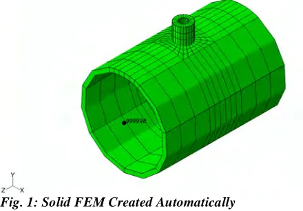
SOLID FEM - CREATED BY A FORTRAN PROGRAM
The proposed method is explained in an example. The FEM, whose Abaqus input deck was created automatically by a
computer program, is shown in Figure 1.
3.1
Geometry
The origin of the FEM is at the intersection of the cylinder
and nozzle axes Z and Y, respectively. The dimensions of
the model, entered by the user are: outer radii of shell (ORS)
and nozzle (ORN) and their wall thicknesses (TS, TN). The
model is made out of quadratic 20 node elements (Type
C3D20R [4] is used as a default; alternatively type C3D20
may be used in cases when a numerical singularity is
encountered; so far it did not happen while using the
method.)
3.2
Boundary Conditions and Constraints
Tip of the nozzle nodes are kinematically coupled to the reference node #999999 (located on the Y axis), except that the
nodes are free to move in the radial direction. Similarly, the nodes of the vessel end faces are kinematically coupled
(except radial direction) to their reference nodes #999997, #999998, located in the centres of the end faces. The two
nodes are restrained as ending points of a “simple supported beam” (At #999997 Ux=Uy=Uz= z=0 and at #999998
Ux=Uy= z=0).
3.3
Loading Conditions
The input deck, considers seven “unit” load cases which are defined in Abaqus steps. In the first step, the pressure of
1000 psi is applied to the inner surface of the structure and the end-cap loads are applied at reference nodes #999999
and #999998. In the remaining steps the loads are: Fx = 1000 lb (2nd step), Fy = 1000 lb… and Mz = 1000 lb-in (7th
step); all these concentrated forces are applied at node #999999. The default location of this node is where axis Y
punctures the outer vessel surface. (The location can be modified to the location where the nozzle loads are given.)
3.4
Stress Area of Interest
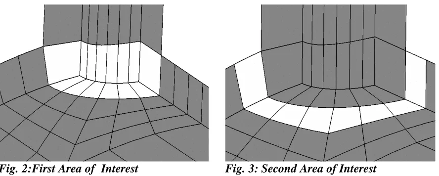
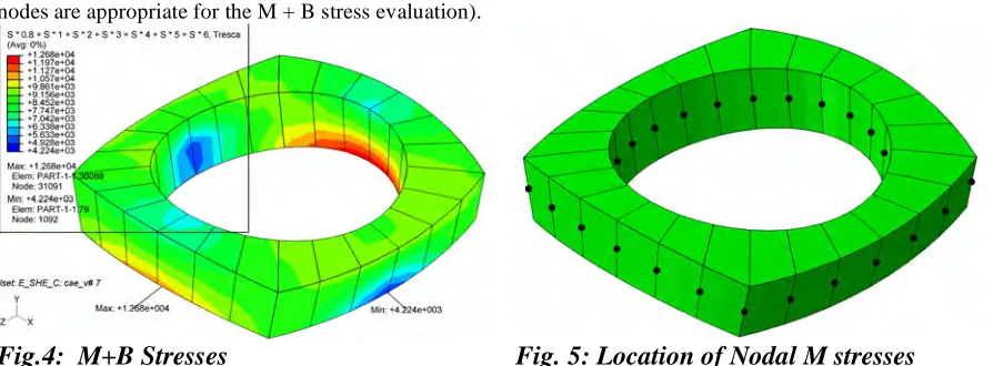
In the ASME code stress analysis the main areas of interest are: (1) the inner edge of the nozzle/vessel intersection (the
pressure stresses are dominant in this area) and (2) the cross section of the vessel shell by the outer surface of the nozzle
(the stresses caused by the nozzle loads are dominant in this area). The elements relevant to the two areas of interest are
highlighted in Figs. 2 and 3.
Fig. 2:First Area of Interest
Fig. 3: Second Area of Interest
Since the mechanical nozzle load causes maximum stresses at the second area of interest and because only this region is
discussed in [1, 2], this paper concentrates also on this region, even though the method applies to both regions. In
ASME stress evaluation [5], the key stress components are membrane (M) and membrane plus bending stress (M + B).
The M components are the averaged through thickness stress components and M + B are linearized stress components
with respect to the thickness variable. The major acceptance criteria of [5] are that the Tresca invariants evaluated for
membrane and membrane plus bending are below the material limits. For simplicity, the two Tresca stresses are further
denoted as M and M + B, unless otherwise described.
3.5
Automatic Generation of the FEM
The Abaqus input deck for the model shown in Fig. 1 was generated by FORTRAN program cyl_sol, whose source
code is given at the end of the paper, by the command “
cyl_sol 4 22 2 2 6 3
” The first four program parameters describe
geometry and they are:
ORN = 4”, ORS = 22”, TN = 2”, TS = 2”
. The last two parameters define the mesh and they
stand for the number of elements per 90 degree of nozzle circumference and the number of elements per nozzle length.
The name of the input deck
sol_4_22_2_2_6_3.inp
is directly associated with the parameters used. If the user does not
know the program parameters they are displayed once the name of the program is entered. The last two parameters
define the mesh density of the model. By comparing results obtained for different mesh density it can be concluded that
the mesh parameters, 6 and 3 used in this example, are appropriate for all practical cases
.
3.6
Example of Evaluation of Local Stresses
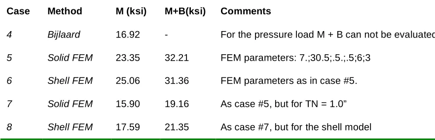
Abaqus nodal stresses. The nodes to be used for the evaluation of the M stresses are highlighted in Fig. 5 (the other
nodes are appropriate for the M + B stress evaluation).
Fig.4: M+B Stresses
Fig. 5: Location of Nodal M stresses
An example of the output produced by a post-processing program (the source code of the post-processing program
com_cyl_sol
, is not complicated; therefore due to the paper size limit it is not provided) is presented below:
**com_cyl_sol;2009-04-08;07:54:44;G:\data\andrzej\TIP\abaqus_t\NOZZLE~1\NOZ_2_~1\sol_FEM\smirt
** cmd_arg: sol_4_22_2_2_6_3
Notes on stress evaluation
Extrnl load applied at nozzle-axis/outer-shell-surf intrsctn
The load units are: psi (pressure), lbf (forces), in-lbf (mom)
Y - nozzle axis, Z - vessel axis
Origin is at the intersection of vessel/nozzle axes
For the load: p, Fx, Fy, Fz, Mx, My, Mz
0.8000E+03 0.1000E+04 0.2000E+04 0.3000E+04 0.4000E+04 0.5000E+04 0.6000E+04
Tresca_max at the outer surfaces x-section is:
0.9888E+04 30087 30587 <= M , EL#. NODE#
0.1268E+05 30089 31091 <= M + B, EL#. NODE#
For the load: p, Fx, Fy, Fz, Mx, My, Mz
0.1000E+04 0.0000E+00 0.0000E+00 0.0000E+00 0.0000E+00 0.0000E+00 0.0000E+00
Tresca_max at the outer surfaces x-section is:
0.1225E+05 87 587 <= M , EL#. NODE#
0.1588E+05 89 1091 <= M + B, EL#. NODE#
Note that highlighted M + B stress of 12680 psi is the same as
in Figure 4, which was produced directly by Abaqus.
4
SHELL FEM
The local stresses can also be evaluated using a shell finite
element model. As for the solid models an automatic pre- and
post-processing is possible for the shell model. For shell FEM
both type of stresses, that is M and M+B can be obtained
directly from Abaqus plot (for solid models only M+B stresses can be obtained). However this visualizing advantage
does not compensate various modelling difficulties like: (i) modelling pressure at the vessel/nozzle inner edge, (ii)
overlapping of the material at the vessel/nozzle intersection, (iii) inability to model through-thickness-pressure-stress
variation (iv) accounting for the stress components which are ignored in shell modelling, and (v) problematic pressure
and end-cap load values (pressure is applied to the mid-surface, instead to the inner surface; it is not possible to find an
equivalent pressure and end-cap loads which meet all theory requirements). The shell-element version of the solid
model is shown in Figure 6; for better visualization only a quarter of the model is shown.
Our shell FEM can be considered as being created from its solid counterpart by removal of its inner and outer
surfaces nodes. As the internal pressure is applied to the mid-shell surface, its value is equal to the actual pressure
prorated by the (inner-radius)/(mid-radius) factor. Note that the most-inner-edge-segments of the vessel and nozzle
(“half” of the highlighted region in Figure 6), are needed only for the purpose of pressure application but these
segments, if not modified, create artificial stiffness at the nozzle/vessel juncture. For this reason, the thickness of these
segments was reduced to 1/10 of the actual thickness. The shell model was made out of S8R [4] elements, except the
four rows of the elements (they are highlighted in Figure 6) in the nozzle/vessel juncture which were made out of S4R
[4] elements.
5
FACTORS AFFECTING SOLUTION
The magnitudes of the local stresses are affected by various factors, among which the most important are: (i) nozzle
wall thickness (with or without reinforcement), (ii) mesh size and (iii) boundary conditions. These three factors can be
easily investigated if the model is generated automatically. The effect of the first two factors, for the structure model
loaded internal pressure of 1000 psi, is illustrated in the table below. It is apparent that the third factor (boundary
conditions) is relevant only for the nozzle loads and it is more significant the larger the ORN/ORS ratio is, therefore this
factor is not discussed in the paper.
Table 1:
Effect of the Mesh and the Nozzle Thickness on M and M+B (only p = 1000 psi load)
Case Model
Parameters
M
(ksi)
M+B
(ksi)
Comments
1
4 22 2 2 6 3
12.25
15.88
Benchmark case (solid FEM)
2
4 22 1 2 6 3
17.00
22.06
As case #1 but with 1” nozzle thickness
3
4 22 2 2 8 4
12.11
15.90
As case #1 but with finer mesh
1sh
4 22 2 2 6 3
13.70
15.07
As case #1 but for the shell model
2sh
4 22 1 2 6 3
19.42
20.36
As case #2 but for the shell model
3sh
4 22 2 2 8 4
13.70
15.28
As case #3 but for the shell model
The results indicate that the nozzle thickness significantly affects M and M+B stresses (compare cases 1 vs. 2 and 1sh
vs. 2sh); the mesh size has smaller effect (compare cases 1 vs. 3 and 1sh vs. 3sh) than the type of the model (solid or
shell). (The accuracy of using one element through thickness approach in the evaluation of the M+B stresses has been
discussed in [3].)
6
RESULTS OBTAINED IN THREE DIFFERENT APPROACHES
To illustrate the differences between the results obtained by different methods, the stresses were evaluated for the data
of example 7 from [2] using (1) formulas and coefficients from [2], and (2) solid FEM and (3) shell FEM discussed
before. The geometry of the example is defined by ORS = 30.5”, ORN=7.0”, TS=0.5”, TN=0.5”.
Table 2:
Pressure Stresses Obtained by Different Methods (p = 150 psi)
Case
Method
M (ksi)
M+B(ksi)
Comments
4
Bijlaard
16.92
-
For the pressure load M + B can not be evaluated
The results illustrate that for this particular case the local stresses are underestimated by the classical method used in
[1,2] (based on Bijlard’s original works assuming that nozzle/attachments are rigid.) Furthermore, the results indicate a
significant effect of the nozzle thickness upon the stresses, but this effect is ignored in the classical approach
7
CONCLUSIONS
The following conclusions can be made from the consideration presented here.
•
The Bijlaard method, a very useful method prior to the invention of the finite element method, should be
replaced by the finite element method.
•
The values of the stresses at the nozzle/vessel junction are significantly affected by the two factors: (1)
nozzle-wall-thickness/vessel-wall-thickness ratio and (2) boundary conditions; both factors are considered in the finite
element method, but not in [1, 2].
•
Generation of the finite element model and evaluation of the stresses can be easily automated by computer
programs.
•
For evaluation of the local stresses, solid element modelling appears to be more appropriate than shell element
modelling.
•
Solid element modelling enables reasonable assessment of stresses in both areas of interests (very inner edge
and vessel cross-section), while the shell element modelling appears to be appropriate only to the second area
of interest.
•
Solid element models created by a computer program have consistent element and node numbering; therefore
these models can be easily adjusted to actual geometry, boundary conditions, nozzle reinforcement and loading
conditions.
ACKNOWLEDGEMENTS
The authors would like to express gratitude to Ontario Power Generation for sponsoring this work.
NOMENCLATURE
FEA - Finite Element Analysis
FEM - Finite Element Model
ORN - Outer Radius of the Nozzle
ORS - Outer Radius of the Shell (Vessel)
TN - wall Thickness of the Nozzle
TS - wall Thickness of the Shell (Vessel)
REFERENCES
[1]
Wichman, K.R., Hopper, A.G. and Mershon, J.L., 1965,
“Local Stresses in Spherical Shells due to External
Loading”, Welding Research Council Bulletin 107, October 20 Update of the March 1979 Revision (original,
August 1965), pp. 68-70.
[2]
Forman B. F., 1981, “Local Stresses in Pressure Vessels”, Third Edition, Pressure Vessel Handbook Pub.
[3]
Strzelczyk, A., Ho S., 2007, “Evaluation of “Linearized” stresses without Linearization” Proceedings of
PVP2007-ICPVT-11 (2007 PVP Conference in San Antonio).
[4]
Abaqus FE Code, V.6-8, Dassault Systems Simulia Inc.,2008
[5]
ASME Code, Section III, Division 1, Sub-section NB., 2008
LISTING OF THE CYL_SOL FORTRAN PROGRAM
The program whose listing is below can be compiled with GNU G77 FORTRAN compiler. Note the order of
listing: first column one through all pages, then column two.
c--- program cyl_sol c---
c The load is applied at the intersection of the nozzle axis with c the outer surface of the shell at its values are:
c p = 1000 psi; (Fx,Fy,Fz) = 1000. lbf; (Mx,My,Mz) = 1000. in-lbf c The origin is at nozzle/cylinder axes intersection
c y is nozzle axis, z is cylinder axes c
c output:(12) cyl_sol.log c (14) - Abaqus main deck
+,'*kinematic coupling,ref node=999999,orientation=o_tip' +,'**'
+,'** Cplng with 2,6 appeaRIS to get better dfrmtn results but for' +,'** solid elements only 2,3 can be used.'
+,'**' +,'n_tip,2,3'
+,'*kinematic coupling,ref node=999997,orientation=o_z' +,'n_zmin_all,2,3'
+,'*kinematic coupling,ref node=999998,orientation=o_z' +,'n_zmax_all,2,3'
c (15) - *.outside_nodes (include file) c - *.inside_nodes (include file) c external getarg parameter (NARG=8,INC_P_E=1000) logical firstt character*20 arg_i,line*180,fname*80,faba*80,fout*80 +,R_noz*10,R_she*10,o*1 dimension arg_i(NARG) c
i_ = 0 firstt = .true.
call echo_arg_line(iendl,line,n,arg_i) open(12,file='cyl_sol.log',status='replace') read(arg_i(1),*,end=998,err=998) ORN read(arg_i(2),*,end=998,err=998) ORS read(arg_i(3),*,end=998,err=998) tn read(arg_i(4),*,end=998,err=998) ts read(arg_i(5),*,end=998,err=998) n_ediv read(arg_i(6),*,end=998,err=998) n_ecir
if (ORN.gt.ORS) stop '#cyl_sol: R-mid-nozzle > R-mid-shell?' pi = atan(1.)*4.
fn = 1. fs = 1.
write(R_noz,'(e10.4)') 1000. * pi * (ORN-tn)**2 write(R_she,'(e10.4)') 1000. * pi * (ORS-ts)**2 if (mod(n_ediv,2).ne.0) goto 998
n_div = 2 * n_ediv N_I = n_div+1 if (n.eq.NARG) then
read(arg_i(7),*,end=998,err=998) zmax read(arg_i(8),*,end=998,err=998) ymax elseif (n.eq.NARG-2) then
ymax = ORS + 2*ORN zmax = ORS + 2*ORN else
goto 998 endif c
c ns is the shift number and NQI1 is total number of nodes in a quater c
n_cir = 2 * n_ecir ns = n_cir*N_I
n_ex = N_I * (4 * n_ecir + 1)+1 NQI1 = n_ex+n_cir**2-1+ns + n_cir
write(*,'(i6,a)') nqi1,' <= last number on the outer surface' if (nqi1*2>INC_P_E) stop '#cyl_sol: increase size of INC_P_E' c
c delta indicates how much needs to be subtrated in the c circumference to get the highest coordinate of 2 * ORN c
delta = ORS * pi/2. - 2 * ORN faba=arg_i(1)(1:lenli1(arg_i(1)))//'_'//
+arg_i(2)(1:lenli1(arg_i(2)))//'_'//arg_i(3)(1:lenli1(arg_i(3)))// +'_'//arg_i(4)(1:lenli1(arg_i(4)))//'_'//
+arg_i(5)(1:lenli1(arg_i(5)))//'_'//arg_i(6)(1:lenli1(arg_i(6))) ifaba = lenli1(faba)
fname='cyl_sol.'//faba(1:ifaba) fout='sol_'//faba(1:ifaba)//'.inp' open(14,file=fout,status='replace') call dattim(14,'cyl_sol')
fout='sol_'//faba(1:ifaba)//'_q.outside_nodes' write(14,'(a)') '** or_n or_s t_n t_s e_n_div e_s_div' +,'** '//line(1:iendl)
+,'*heading','*preprint,model=yes,echo=yes'
+,'*include,input='//'sol_'//faba(1:ifaba)//'_q.outside_nodes' +,'*include,input='//'sol_'//faba(1:ifaba)//'_q.inside_nodes' o = ' '
1000 open(15,file=fout,status='replace') call dattim(15,'cyl_sol')
write(15,'(a)') '*node,nset=n_ins'//o do 100 i=1,n_ediv + 1
gamma = (pi/2.)/n_div * (i-1) z = ORN * sin(gamma) x = ORN * cos(gamma) alpha = pi/2. - asin(x/ORS) w = alpha * ORS - delta c
c w is the true distance measured in circumferential direction
+,'999997,1,3','999997,6,6','999998,1,2','999998,6,6' +,'*nfill','n_juncture1,n_edge,2,'//str6
write(14,'(a)') '*element,type=c3d20r' N_I1 = n_cir + 1
n1 = n_ex + N_I1 + ns
write(14,'(16(i6,'',''))') 1,1,1+N_I*2,N_I*2+3,3 +, 1+3*I_,1+N_I*2+3*I_,N_I*2+3+3*I_,3+3*I_ +,N_I+1,N_I*2+2,N_I+3,2
+,N_I+1+3*I_,N_I*2+2+3*I_,N_I+3+3*I_ write(14,'(i6,4('','',i6))') ,2+3*I_
+, 1+3*n_h,1+N_I*2+3*n_h,N_I*2+3+3*n_h,3+3*n_h write(14,'(16(i6,'',''))') 1+ns,1+ns,1+N_I*2+ns,N_I*2+3+ns +,3+ns +,1+ns+I_,1+N_I*2+ns+I_,N_I*2+3+ns+I_,3+ns+I_ +,N_I+1+ns,N_I*2+2+ns,N_I+3+ns,2+ns +,N_I+1+ns+I_,N_I*2+2+ns+I_,N_I+3+ns+I_ write(14,'(i6,4('','',i6))') 2+ns+I_ +,1+ns+n_h,1+N_I*2+ns+n_h,N_I*2+3+ns+n_h,3+ns+n_h write(14,'(16(i6,'',''))')
+n1 ,n1 ,n1+2 ,n1+2+2*N_I1 ,n1+2*N_I1 + ,n1+I_,n1+2+I_,n1+2+2*N_I1+I_,n1+2*N_I1+I_ + ,n1+1 ,n1+2+N_I1,n1+2*N_I1+1,n1+N_I1 + ,n1+1 +I_,n1+2+N_I1+I_,n1+2*N_I1+1+I_ write(14,'(i6,4('','',i6))') n1+N_I1+I_
+,n1+n_h,n1+2+n_h,n1+2+2*N_I1 +n_h,n1+2*N_I1+n_h write(14,'(16(i6,'',''))')
+2+ns,ns+1, ns+1+i_ ,ns+3+i_ ,ns+3 + ,ns+1+3*i_, ns+1+4*i_,ns+3+4*i_ ,ns+3+3*i_ + ,ns+1+n_h , ns+2+i_ ,ns+3+n_h ,ns+2 + ,ns+1+7*n_h,ns+2+4*i_,ns+3+7*n_h write(14,'(i6,4('','',i6))') ,ns+2+3*i_
+ ,ns+1+3*n_h, ns+1+5*n_h,ns+3+5*n_h,ns+3+3*n_h write(14,'(a)') '*element,type=c3d20r,elset=e_she1' write(14,'(16(i6,'',''))')
+nco+1+ns ,nco+ns ,n1 ,nco+2*N_I+2+ns ,nco+2+ns + ,nco+ns +I_,n1+I_,nco+2*N_I+2+ns +I_,nco+2+ns+I_ + ,n_ex+ns ,nco+2*N_I+1+ns,nco+2+N_I+ns, nco+1+ns + ,n_ex+ns +I_,nco+2*N_I+1+ns+I_,nco+2+N_I+ns+I_ write(14,'(i6,4('','',i6))') nco+1+ns+I_
+,nco+ns +n_h,n1 +n_h,nco+2*N_I+2+ns +n_h,nco+2+ns+n_h write(14,'(a)')
+'** N_IN_ecirn_ediv ns n_ex nlas nco n1' write(14,'(a,9i6)') '**',N_I,n_ecir,n_ediv,ns,n_ex,nlas,nco,n1 last = nlas + 4 * n_ecir * N_I
do 90 i=1,n_ecir-1 iat = i*2*N_I iab = (i-1)*2*N_I1
write(14,'(16(i6,'',''))') nco+1+iat+ns,n1+iab,n1+iab+N_I1*2 +,nco+iat+2+2*N_I+ns,nco+iat+2+ns +,n1+iab+I_,n1+iab+N_I1*2+I_,nco+iat+2+2*N_I+ns+I_ +,nco+iat+2+ns+I_ +,n_ex+iab+2*N_I1+ns,nco+iat+1+2*N_I+ns +,nco+iat+2+N_I+ns,nco+1+iat+ns +,n_ex+iab+2*N_I1+ns+I_,nco+iat+1+2*N_I+ns+I_ +,nco+iat+2+N_I+ns+I_ write(14,'(i6,4('','',i6))') nco+1+iat+ns+I_,n1+iab+n_h, +n1+iab+N_I1*2+n_h,nco+iat+2+2*N_I+ns+n_h,nco+iat+2+ns+n_h 90 continue
do 100 i=1,n_ecir ia1 = (i-1)*2*N_I ia2 = (i-1)*2 write(14,'(16(i6,'',''))')
+nco+N_I+ia1+ns,nco+ia1+ns,nco+N_I*2+ia1+ns, n1+2+ia2,n1+ia2 +,I_+nco+ia1+ns,I_+nco+N_I*2+ia1+ns,I_+ n1+2+ia2,I_+n1+ia2 + ,nco+N_I+ia1+ns,n_ex+2+ia2+ns,n1+1+ia2,n_ex+ia2+ns +,I_+nco+N_I+ia1+ns,I_+n_ex+2+ia2+ns,I_+n1+1+ia2
write(14,'(i6,4('','',i6))') I_+n_ex+ia2+ns +,n_h+nco+ia1+ns,n_h+nco+N_I*2+ia1+ns,n_h+ n1+2+ia2,n_h+n1+ia2
100 continue
c
write(15,'(a)') '** '
+ ,'** intersection node number and its coordinates','**' call w2xy(delta,w,ORS,x3d,y3d)
call wcoo(firstt,fs,fn,3,i_, i+ns,x3d,y3d,z) dz = (2 * ORN / n_ediv * (i-1) - z)/N_CIR dw = w/N_CIR
do 110 j=1,N_CIR wj = w-dw*j
call w2xy(delta,wj,ORS,x3d,y3d)
call wcoo(firstt,fs,fn,1,i_,i+N_I*j+ns,x3d,y3d,z+dz*j) 110 continue
100 continue
ors = sqrt(x3d**2 + y3d**2) top_angle = asin(x3d/ors) if (y3d.gt.0) then
bottom_angle = pi - top_angle else
bottom_angle = top_angle endif
do 200 i=n_ediv + 2, 2 * n_ediv + 1 gamma = (pi/2.)/n_div * (i-1) z = ORN * sin(gamma) x = ORN * cos(gamma) alpha = pi/2. - asin(x/ORS) w = alpha * ORS - delta c
c w is the true distance measured in circumferential direction c
call w2xy(delta,w,ORS,x3d,y3d) write(15,'(a)') '** '
+ ,'** 2nd pattern intersection node# and its coordinates','**' call wcoo(firstt,fs,fn,3,i_, i+ns,x3d,y3d,z)
dz = (2 * ORN - z)/N_CIR
dw = (w - (2 * ORN)/n_ediv * (i - n_ediv -1))/N_CIR do 210 j=1,N_CIR
wj = w-dw*j
call w2xy(delta,wj,ORS,x3d,y3d)
call wcoo(firstt,fs,fn,1,i_,i+N_I*j+ns,x3d,y3d,z+dz*j) 210 continue
200 continue
call write_end(n_ex,NQI1,firstt,i_,fn,fs,pi,N_I,n_ecir +,ORS,ORN,R_noz,R_she,bottom_angle,ymax,zmax) if(firstt) then
firstt = .false. i_ = INC_P_E o = '1'
fout='sol_'//faba(1:ifaba)//'_q.inside_nodes ' fn = 1. - tn/ORN
fs = 1. - ts/ORS goto 1000 endif write(*,'(a)') ''
+,'sol_'//faba(1:ifaba)//'.inp <= Abaqus input deck','', +'sol_'//faba(1:ifaba)//'_q.inside_nodes <= include file','', +'sol_'//faba(1:ifaba)//'_q.outside_nodes <= include file','' stop
998 write(*,'(a)') 'FORMAT: cyl_sol or_noz or_shell ' * +//'t_noz t_shell e_noz_div e_shell_div [ymax zmax]' +//'t_noz t_shell e_noz_div e_shell_div'
stop end c******************************************************************** subroutine write_end(n_ex,NQI1,firstt,i_,fn,fs,pi,N_I,n_ecir +,ORS,ORN,R_noz,R_she,bottom_angle,ymax,zmax) c******************************************************************** logical firstt character*6 ninc,ninc2,ninc3,str6,str6_3,R_noz*10,R_she*10,o*1 c
if (firstt) then o=' ' else o='1' endif n_h = i_/2 NI =N_I
n_ediv = (N_I - 1)/2 n_cir = 2 * n_ecir NI1 = n_cir + 1
+ 1+ ns,2,N_I * 2 * n_ecir,N_I * 2 * n_ecir write(14,'(i6,3('','',i6))') 1+ ns,2,nco + 1,nco+1
write(14,'(i6,6('','',i6))') ns+N_I * 2 * n_ecir+1,n_ediv/2,2,2 +,n_ecir,N_I*2,N_I*2 write(14,'(i6,6('','',i6))') ns+nco+2,n_ediv/2-1,2,2,n_ecir +,2*N_I,2*N_I write(14,'(i6,6('','',i6))') n1,n_ecir,2,2,n_ecir-1 +,(n_cir+1)*2,(n_cir+1)*2 write(14,'(a)') '*elset,elset=e_she1_c,generate' write(14,'(i6,2('','',i6))') 1+ns,1+ns+2*(n_ediv-1),2
write(14,'(a)') '*solid section,elset=e_no_all,material=m_solid' +,'*solid section,elset=e_sh_all,material=m_solid'
+,'*material,name=m_solid' +,'*elastic'
+,'3.e7,0.3' +,'**'
+,'** creation of the other three quadrants' +,'**'
+,'*nset,nset=n_q1,elset=e_noz1' +,'*nset,nset=n_q1,elset=e_she1'
+,'*ncopy,reflect=mirror,old set=n_q1,new set=n_q2,change number'//
+ '=10000' +,'0.,0.,0.,1.,0.,0.' +,'0.,1.,0.'
+,'*ncopy,shift,old set=n_q1,new set=n_q3,change number=20000' +,'0.,0.,0.'
+,'0.,0.,0.,0.,1.,0.,180.'
+,'*ncopy,reflect=mirror,old set=n_q1,new set=n_q4,change number'//
+ '=30000' +,'0.,0.,0.,0.,0.,1.' +,'0.,1.,0.'
+,'*elcopy,old set=e_noz1,new set=e_noz2,element shift=10000,'// +'reflect,shift nodes=10000'
+,'*elcopy,old set=e_noz1,new set=e_noz3,element shift=20000,'// +'shift nodes=20000'
+,'*elcopy,old set=e_noz1,new set=e_noz4,element shift=30000,'// +'reflect,shift nodes=30000'
+,'*elcopy,old set=e_she1,new set=e_she2,element shift=10000,'// +'reflect,shift nodes=10000'
+,'*elcopy,old set=e_she1,new set=e_she3,element shift=20000,'// +'shift nodes=20000'
+,'*elcopy,old set=e_she1,new set=e_she4,element shift=30000,'// +'reflect,shift nodes=30000' +,'*elset,elset=e_sh_all' +,'e_she1,e_she2,e_she3,e_she4' +,'*elset,elset=e_no_all' +,'e_noz1,e_noz2,e_noz3,e_noz4' +,'*mpc' +,'tie,n_yz4,n_yz1' +,'tie,n_yz3,n_yz2' +,'tie,n_xy2,n_xy1' +,'tie,n_xy4,n_xy3' do 180 i=1,3
write(14,'(a,2('','',i6))') 'tie',last-NI+1+n_h*(i-1)+20000 + ,last-NI+1+n_h*(i-1)
180 continue
write(14,'(a)') '*elset,elset=e_she_c,generate' do 105 j=1,4
JNQ = (j-1)*10000
write(14,'(i6,2('','',i6))') 1+ns+JNQ,1+ns+2*(n_ediv-1)+JNQ,2 105 continue
write(14,'(a)') '*elset,elset=e_ed_4,generate' do 200 i=1,2
ka = (i - 1)*20000
write(14,'(i6,2('','',i6))') ns+2+ka,ns+2+ka+(n_ediv-1)*2,2 200 continue
write(14,'(a)') '*elset,elset=e_ed_5,generate' do 210 i=1,2
ka = i*20000 - 10000
write(14,'(i6,2('','',i6))') ns+2+ka,ns+2+ka+(n_ediv-1)*2,2 210 continue
ns = n_cir*N_I
write(15,'(a)') '*nset,generate,nset=n_line'//o write(15,'(i6,a,i6)') N_I * 2 * n_ecir+1+ns+i_ +,',',N_I * 2 * n_ecir+1+n_ediv+ns+i_
write(15,'(a,i6,a,i6)') '*ncopy,NEW SET=N_O'//o//',shift,old set=' +//'n_line'//o//',change number=',N_I,',multiple=',n_cir-1 angle = bottom_angle*180/pi/n_cir
write(15,'(a/a,f10.7)') '0.,0.,0.','0.,0.,0.,0.,0.,-1.,',angle write(15,'(a)') '*nset,generate,nset=n_cline'//o nlas = N_I * (n_cir + 1)
nco = nlas - n_ediv last = nlas + 4 * n_ecir * N_I
write(15,'(i6,a,i6)') nco+1+ns+i_,',',nlas+ns+i_ write(15,'(a,i6,a)') '*ncopy,shift,change number=',ns +,',old set=n_cline'//o//',new set=n_zmax'//o deltaz = zmax - 2 * ORN
write(15,'(a,e14.8)') '0.,0.,',deltaz write(15,'(a)') '0.,0.,0.,0.,0.,-1.,0' +,'*nfill,NSET=N_O'//o
write(15,'(2(a,i6))') 'n_cline'//o//',n_zmax'//o//',',n_cir,',' +,N_I
write(15,'(a)') '**','** non-typical segment nodes','**' +,'*nset,nset=n_corner'//o
write(15,'(i6,a)') nco+ns+i_,','
write(15,'(a,i6,a)') '*ncopy,NEW SET=N_O'//o// +',shift,change number=',nco,',old set=n_corner'//o write(15,'(a,e14.8)') '0.,0.,',deltaz/n_cir
write(15,'(a)') '0.,0.,0.,0.,0.,-1.,0,'
write(15,'(a,i6)') '*ncopy,NEW SET=N_O'//o//',shift,old set='// +'n_corner'//o//',change number=',nco + n_cir**2 - 1 write(15,'(a,e14.8)') '0.,0.,',deltaz
write(15,'(a)') '0.,0.,0.,0.,0.,-1.,0,' +,'*ngen,nset=N_L1'//o NQI2 = nqi1 * 2 write(ninc,'(i6)') NQI1 write(ninc2,'(i6)') NQI1*2 write(ninc3,'(i6)') NQI1*3
write(15,'(i6,2('','',i6))') n_ex+ns+i_,n_ex+n_cir**2-1+ns+i_ +,n_cir+1
write(15,'(a,i6)') '*ncopy,NEW SET=N_O'//o//',shift,old set='// +'N_L1'//o//
+',change number=1,multiple=',n_cir-1
write(15,'(a/a,f10.7)') '0.,0.,0.','0.,0.,0.,0.,0.,-1.,',angle c
c bottom line nodes c write(15,'(a)') '*node' call wrispe(15,last-NI+1+i_,0.,-ORS*fs,0.) call wrispe(15,last-n_ediv+i_,0.,-ORS*fs,2*ORN) call wrispe(15,last+n_cir+1+i_,0.,-ORS*fs +,2*ORN+(2*ORS-2*ORN)/n_cir) call wrispe(15,NQI1+i_-NI1+n_cir+1,0.,-ORS*fs,ORS+2*ORN) write(15,'(a)') '*ngen' write(15,'(i6,2('','',i6))') last-NI+1+i_,last-n_ediv+i_,1 write(15,'(i6,2('','',i6))') last+n_cir+1+i_,NQI1+i_-NI1+n_cir+1 +,n_cir+1 c
c nozzle nodes c
write(15,'(a)') '*node,nset=n_1'//o
write(15,'(i6,2('','',e14.8))') 1+3*i_,ORN*fn,ymax write(15,'(a,i6)') '*ncopy,shift,old set=n_1'//o//
+',change number=1,new set=n_top'//o//',multiple=',N_I-1 write(15,'(a/a,e14.8)') +,'0.,0.,0.','0.,0.,0.,0.,-1.,0.,',90./(N_I-1) write(15,'(a)') '*nset,nset=n_top'//o +,'n_1'//o//',' +,'*nset,nset=n_juncture'//o//',generate' write(15,'(i6,a,i6)') ns+1+3*i_,',',ns+N_I+3*i_ write(15,'(a/a,i6,a,i6)') '*nfill,NSET=N_O'//o +,'n_top'//o//',n_juncture'//o//',',n_cir,',',N_I if (firstt) return
write(15,'(a)') '*nset,nset=n_edge,generate' write(15,'(i6,a,i6)') ns+1+4*i_,',',ns+N_I+4*i_ do 8 k=1,4
ka = (k - 1)*10000
write(14,'(a/a,i1,a)') '**','*nset,nset=n_yz',k,',generate' do 10 i=1,3
+,'*cload'
+,'**','** End-cap-load 1000. * pi * r_inside**2','**' +,'** 1000. * pi * rin**2/4.'
+,'** 1000. * pi * ris**2/2.' +,'999999,2,'//R_noz +,'999998,3,'//R_she +,'**' +,'*el print,elset=e_she_c,position=nodes' +,'s,tresc' +,'*el print,elset=e_she_c,position=centroid' +,'s,tresc' +,'*el print,elset=e_edge,position=nodes' +,'s,tresc' +,'*el print,elset=e_edge,position=centroid' +,'s,tresc' +,'*node print,total=yes,global=yes' +,'u1,u2,u3,rf,' +,'*end step' +,'*step','Fx = 1000.'
+,'*static','1.,,,','*dload,op=new','*cload,op=new' +,'999999,1,1000.','*end step'
+,'*step','Fy = 1000.' +,'*static','1.,,,','*cload,op=new' +,'999999,2,1000.','*end step' +,'*step','Fz = 1000.' +,'*static','1.,,,','*cload,op=new' +,'999999,3,1000.','*end step' +,'*step','Mx = 1000.' +,'*static','1.,,,','*cload,op=new' +,'999999,4,1000.','*end step' +,'*step','My = 1000.' +,'*static','1.,,,','*cload,op=new' +,'999999,5,1000.','*end step' +,'*step','Mz = 1000.' +,'*static','1.,,,','*cload,op=new' +,'999999,6,1000.','*end step' return end c*************************************** subroutine w2xy(delta,w,ORS,x3d,y3d) c***************************************
c based on delta,w,ORS find x and y (space coordinates, z is unchanged)
c
w_true = w + delta alpha = w_true / ORS x3d = ORS * cos(alpha) y3d = ORS * sin(alpha) return
end
c****************************************************** subroutine wcoo(firstt,fs,fn,itype,i_,node,x,y,z) c****************************************************** c itype = 1 <= (node on the shell part only) c = 2 <= (node on the nozzle part only) c = 3 <= (node at the junction)
logical firstt if (firstt) then
call wrispe(15,node,x,y,z) else
if (itype.eq.1.or.itype.eq.3) then xs = x * fs
ys = y * fs zs = z
call wrispe(15,node+i_,xs,ys,zs) elseif (itype.eq.2) then xf = x * fn
yf = y zf = z * fn
call wrispe(15,node+3*i_,xf,yf,zf) endif
if (itype.eq.3) then ris = sqrt(xs**2 + ys**2) xf = x * fn
yf = y zf = z * fn
k_ = (i-1)*n_h + ka if (i.eq.1) then
write(14,'(i6,'','',i6,'','',i6)') NI+k_,last+k_,NI elseif (i.eq.2) then
write(14,'(i6,'','',i6,'','',i6)') ns+N_I+k_,last+k_,NI*2 else
write(14,'(i6,'','',i6,'','',i6)') ns+N_I+k_,last+k_,NI endif
if (i.eq.2) then
write(14,'(i6,'','',i6,'','',i6)') last-NI+3+k_,last-n_ediv+k_,2 else
write(14,'(i6,'','',i6,'','',i6)') last-NI+2+k_,last-n_ediv+k_,1 endif
if (i.eq.2) then
write(14,'(i6,'','',i6,'','',i6)') last+n_cir+1+NI1+k_,NQI1+k_ + ,NI1*2
else
write(14,'(i6,'','',i6,'','',i6)') last+n_cir+1+k_,NQI1+k_,NI1 endif
10 continue
write(14,'(i6,'','',i6,'','',i6)') NI+3*n_h+ka,ns+N_I+3*n_h+ka +,2*NI
+,NI+3*i_+ka,ns+N_I+3*i_+ka,NI +,ns+N_I+5*n_h+ka,ns+N_I+4*i_+ka,n_h
write(14,'(a/a,i1,a)') '**','*nset,nset=n_xy',k,',generate' do 20 i=1,3
k_ = (i-1)*n_h j_= NI
if (i.eq.2) j_= NI + NI
write(14,'(i6,'','',i6,'','',i6)') 1+3*k_+ka,ns+1+3*k_+ka,j_ write(14,'(i6,'','',i6,'','',i6)') ns+1+k_+ka,last-NI+1+k_+ka,j_ 20 continue
write(14,'(i6,'','',i6,'','',i6)') ns+1+5*n_h+ka,ns+1+4*i_+ka +,n_h
8 continue
write(14,'(a)') '*nset,nset=n_tip,generate' do 28 k=1,4
do 30 i=1,3
k_ = 3* (i-1)*n_h + (k - 1) * 10000 if (k.eq.1) then
if (i.eq.2) then
write(14,'(i6,'','',i6,'','',i6)') 1+k_,NI+k_,2 else
write(14,'(i6,'','',i6,'','',i6)') 1+k_,NI+k_,1 endif
elseif (k.eq.2) then if (i.eq.2) then
write(14,'(i6,'','',i6,'','',i6)') 3+k_,NI+k_,2 else
write(14,'(i6,'','',i6,'','',i6)') 2+k_,NI+k_,1 endif
elseif (k.eq.3) then if (i.eq.2) then
write(14,'(i6,'','',i6,'','',i6)') 1+k_,NI+k_-2,2 else
write(14,'(i6,'','',i6,'','',i6)') 1+k_,NI+k_-1,1 endif
elseif (k.eq.4) then if (i.eq.2) then
write(14,'(i6,'','',i6,'','',i6)') 3+k_,NI+k_-2,2 else
write(14,'(i6,'','',i6,'','',i6)') 2+k_,NI+k_-1,1 endif
endif 30 continue 28 continue write(14,'(a)') '*node'
c write(14,'(a,e14.8,a)') '999999,0.,',ORS+2*ORN,',0.' write(14,'(a,e14.8,a)') '999999,0.,',ORS,',0.' write(14,'(a,e15.8)') '999998,0.,0.,',zmax write(14,'(a,e15.8)') '999997,0.,0.,',-zmax write(14,'(a)') '*nset,nset=n_zmax_all,generated' nqi3 = NQI1*3
nqi4 = NQI1*4
do 32 k=1,2 j_=0 if (k.eq.2) j_= 1 do 40 i=1,3
* Node on the inner edge *
yf = sqrt(ris**2 - xf**2) call wrispe(15,node+4*i_,xf,yf,zf) xf = (xf + xs)/2.
zf = (zf + zs)/2. yf = sqrt(ris**2 - xf**2) iadd = 5 * i_ / 2
call wrispe(15,node+iadd,xf,yf,zf) endif endif return end c******************** subroutine wrispe(iou,n,x,y,z) c******************** c
c write coodrinates in shortest format c
C
parameter (EPS=1.e-5) character*10 xs,ys,zs c
if (abs(x).gt.EPS) then call wrir10(x,xs) else
call wrir10(0.,xs) endif
if (abs(z).gt.EPS) then call wrir10(z,zs) else call wrir10(0.,zs) endif call wrir10(y,ys) write(iou,'(i6,3('','',a))') n,xs,ys,zs return end c******************** subroutine wrir10(r,stri10) c********************
c return in 10 character string real number c
character strin7*7,stri10*10 c
absr=abs(r)
if (absr.ge.1.e8.or.absr.lt.1.e-5) then if (absr.eq.0.) then
write(stri10,'(a)') '0.0' else
write(stri10,'(e10.4)') r endif
else
do 100 isigni=1,8 if (absr.lt.1.) goto 101 absr=absr*.1 100 continue
101 write(strin7,'(a,i1,a)') '(F10.',9-isigni,')' write(stri10,strin7) r endif return end c*********************************************** function lenli1(string)
c! Get string length without trailing blanks c*********************************************** character string*(*),c_test*1 c
lenli1=len(string) if (lenli1.ne.0) then do 100 i=lenli1,1,-1 c_test = string(i:i) if (c_test.eq.' ') goto 100 if (c_test.eq.char(9)) goto 100 if (c_test.eq.char(0)) goto 100 goto 998
L_ = j_
if (i.eq.2) L_= j_ + j_ k_ = (i-1)*n_h + 30000 * (k-1) if (i.eq.2) then
write(14,'(i6,2('','',i6))') last-n_ediv+2+k_,last+k_-L_,2 write(14,'(i6,2('','',i6))') NQI1-n_cir+k_,NQI1+k_-L_,2 else
write(14,'(i6,2('','',i6))') last-n_ediv+1+k_,last+k_-L_,1 write(14,'(i6,2('','',i6))') NQI1-n_cir+k_,NQI1+k_-L_,1 endif
40 continue 32 continue
write(14,'(a)') '*nset,nset=n_zmin_all,generated' do 132 k=1,2
j_=0 if (k.eq.2) j_= 1 do 140 i=1,3 L_ = j_
if (i.eq.2) L_= j_ + j_ k_ = (i-1)*n_h + 10000 * k if (i.eq.2) then
write(14,'(i6,2('','',i6))') last-n_ediv+2+k_,last+k_-L_,2 write(14,'(i6,2('','',i6))') NQI1-n_cir+k_,NQI1+k_-L_,2 else
write(14,'(i6,2('','',i6))') last-n_ediv+1+k_,last+k_-L_,1 write(14,'(i6,2('','',i6))') NQI1-n_cir+k_,NQI1+k_-L_,1 endif
140 continue 132 continue
write(14,'(a)') '*nset,nset=nn_outside,generated' write(14,'(i6,'','',i6)') 1,ns+N_I
write(14,'(a)') '*nset,nset=nn_inside,generated' write(14,'(i6,'','',i6)') 1+3*i_,ns+N_I+3*i_ write(14,'(a)') '*nset,nset=n_outside,generated' write(14,'(i6,'','',i6)') ns+1,NQI1
write(14,'(a)') '*nset,nset=n_inside,generated' write(14,'(i6,'','',i6)') ns+1+I_,NQI1+I_ write(str6,'(i6)') n_h
write(14,'(a)') '*nfill','n_outside,n_inside,2,'//str6 write(str6_3,'(i6)') n_h*3
write(14,'(a)') 'nn_outside,nn_inside,2,'//str6_3 +,'*orientation,name=o_tip,system=cylindrical' +,'0.,0.,0.,0.,1.,0.','1,0.'
+,'*orientation,name=o_z,system=cylindrical' +,'0.,0.,0.,0.,0.,1.','1,0.'
return end
c******************************** subroutine dattim(io,fname) c******************************** c
c write down date and time c
character dates*8,times*10,fname*(*),defdir*80 integer getcwd
c
ierrno = getcwd(defdir) iend=lenli1(fname)
call date_and_time(dates,times) write(io,'(20a)') '**',fname(1:iend),';' +,dates(1:4),'-',dates(5:6),'-',dates(7:8),';' * +,times(1:2),':',times(3:4),':',times(5:10) +,times(1:2),':',times(3:4),':',times(5:6) +,';',defdir(1:lenli1(defdir))
return end
c************************************************** subroutine echo_arg_line(iend,line,n,arg_i) c************************************************** external getarg,iargc
* character arg_i*80,line*(*) character arg_i*(*),line*(*) dimension arg_i(*) c
n = iargc()
write(*,*) n,'<= value of iargc()' if (n.eq.0) goto 999 do 100 i=1,n
call getarg(i,arg_i(i)) 100 continue
write(line,'(120a)') 'cmd_arg: ' + ,(arg_i(j)(1:lenli1(arg_i(j))),' ',j=1,n) iend = lenli1(line)
do 300 j=1,n if (j.lt.10) then
write(*,'(3a,i1)') '>',arg_i(j)(1:lenli1(arg_i(j))),'< arg',j else
write(*,'(3a,i2)') '>',arg_i(j)(1:lenli1(arg_i(j))),'< arg',j endif
300 continue 999 return end