Sensing Based Spectrum Sharing Using
Optimal Power Allocation Scheme in
Cognitive Radio Network
Soniya S.Christani1, Jigneshkumar N. Patel2
PG Student, Department of ECE, Sardar Vallabhbhai Patel Institute of Technology, Vasad, India1 Assistant Professor, Department of ECE, Sardar Vallabhbhai Patel Institute of Technology, Vasad, India2
ABSTRACT: In this paper, we consider a new spectrum sharing model called sensing based spectrum sharing for cognitive radio network. In our proposed system model, which consists of two steps: In the first step, the secondary user (SU) listens to the spectrum allocated to the primary user (PU) to detect the state of the PU; in the second step, the SU adapts its transit power based on the sensing results. If the PU is inactive, the SU allocates the transmit power based on its own benefit. However, if the PU is active, the interference power constraint is obligatory to protect the PU. Finally, numerical results are presented to validate the proposed studies. It is shown that the SU can achieve a significant capacity gain under the proposed model.
KEYWORDS: Detection Probability, False Alarm Probability, Cooperative Spectrum Sensing, Detection Threshold, Optimal Power Control.
I. INTRODUCTION
Cognitive Radio(CR) is one kind of intelligent wireless device, which is able to adjust its transmission parameters, such as transmit power and transmission frequency band, based on the environment [3]. In a CRN, ordinary wireless devices are referred to as primary users (PUs), and CRs are referred to as secondary users (SUs). Conventionally, a CRN can be formed by allowing either the SUs to opportunistically operate in the frequency bands originally allocated to the PUs when the PUs are inactive or the SUs to coexist with the PUs, as long as the quality of service of the PUs is not degraded to an unacceptable level by the interference from the SUs. The previous transmission technique is known as opportunistic spectrum access, and the later transmission model is known as spectrum sharing. As a promising spectrum sharing scheme, sensing-based spectrum sharing not only improves the throughput of the secondary network but also guarantees the QoS of the primary network. Sensing-based spectrum sharing[5] combines the benefits of both spectrum overlay and spectrum underlay to improve the throughput of the SU, without generating harmful interference to the PU.
In this paper, we propose a new transmission model referred to as sensing-based spectrum sharing. In this model, the SU first senses the frequency band allocated to the PU to detect the state of the PU and then adapts its transmit power according to the detection result. If the PU is inactive, the SU allocates the transmit power based on its own benefit to achieve a higher transmission rate. If the PU is active, the SU transmits with a lower power to avoid causing harmful interference to the PU. This is different from either opportunistic spectrum access or spectrum sharing. In the opportunistic spectrum access [4], the SU transmits only when it detects spectrum holes [3], which are the time duration that the PU is not transmitting over the band. In the spectrum-sharing model[6], the SU can transmit at any time without having to detect whether the PU is active or not. However, it has to restrict its transmit power to not cause harmful interference to the PU during the whole transmission process.
II. SYSTEM MODEL
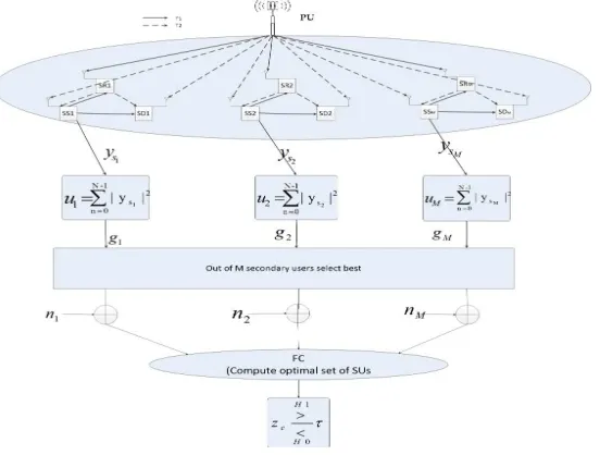
A proposed system model consists of (i) a PU and (ii) a cognitive radio network(CRN), which is shown in figure 1. In our proposed model, a CRN consist of M no. of nodes, i.e. a secondary source(SS); secondary relay(SR); secondary destination(SD) pairs.
Figure. 1. Proposed System Model
Also cognitive radio network operate based on frame by frame. To improve performance in terms of secondary throughput and detection capabilities cooperative communication used. In cooperative communication, Amplify and Forward(AF) or Decode and Forward relaying used. In AF relaying, relay amplify the received signal from the source and retransmit it to the destination. As in AF relaying, each frame consist of two equal time slots T1 and T2. The frame structure of AF relaying is shown below figure.
Figure. 2. Frame structure of AF Relaying
All the channels over the links for M no. of CRN, (PU–SR), (PU–SS), (PU–SD), (SS–SR), (SS–SD), (SR–SD) are modeled to be Rayleigh flat fading channels with coefficients hpr, hps, hpd, hsr, hsd, hrd respectively. Assume that the CRN operates in the first mode, since the second mode is just a modified version of the first one. In the first time slot
T1, the SS will transmit data to both the SR and SD and in the same time the SR and SD will listen to the PU transmissions, as shown in Fig. 2.
The signal received by secondary user source is given by, the measurement model of the two hypotheses corresponding to absence or presence of the primary user at nth time instant sensed by the ith secondary user is given by :
Where, ( ) is received signal by the ith secondary user denotes the primary user signal at time instant k with energy Es, distorted by the channel gains {hsi , where hsi =[hi1; hi2; ; ;hiN ]. denotes the transmitted power from Primary
user (PU) to secondary source(SS). Moreover vsi denotes noise signal vector such that vi ~ CN(0;σi2) are additive white
Gaussian noise (AWGN) with variances σi2=[ σi12, σi22,…, σiN2]. defines the primary user present or absent i.e., if
= 1 then PU is present or = 0 then PU is absent.
The received signals at the SR from the SS and the PU in T1 can be written as:
( ) = ℎ ( ) + , ………..(2)
( ) = ℎ ( ) + , ………..(3)
The combined received signal at the SR in T1 after applying EGC can be deduced as:
( ) = ℎ ( ) + ℎ ( ) + , ………..(4)
In the same manner, the combined received signal at the SD in the first time slot T1 can be written as:
( ) = ℎ ( ) + ℎ ( ) + , ………..(5)
In the second time slot T2, the combined received signal at the SR in T1 will be amplified and retransmitted to the SS and SD and at the same time the SS and SD will listen to the PU transmissions, as shown in Figure.8 The received signal at the SS in T2 can be written as,
( ) =ℎ ( ) + ℎ ( ) + , ………..(6)
As shown in Figure 8, each secondary user measures the energy ui for (l = 1, 2,…, lR) & (i = 1, 2,…, nR) at detection
interval of M samples given as follows:
=∑ | ( )| , ………..(7)
The measured energy (ui ≜ [u1, u2, …, ui]) recieved from lR antennas are combined by equal gain combiner(EGC)
using an equal gain α and output of EGC is transmitted to secondary user. Thus the observation received by each secondary user is given by :
= α ui ,………..(8)
For a sufficiently large M, the central limit theorem implies that the decision statistic ui approximately follows a
Gaussian distribution under the two hypotheses H1 : ( = 1) and H0 : ( = 0). ( ) 1 and ( ) 2 are assumed to be
CSCG random sequences, and ( ) 1, ( ) 2, ur(n)T1, and ud(n)T2 are pairwise independent. Then the mean and
the variance of ui under H1 can be expressed as μi= N μ1 and ∑1 = N μ2 respectively, where, μ1= GpsPp +βGsr
[GprPp+Pu]+Pu. The mean and the variance of ui under H0 can be expressed as μ0= N μ0 and ∑0 = Nμ2 , respectively.
where , μ0 = βGsrPu + Pu.
III. OPTIMAL POWER ALLOCATION
In this section, we formulate the optimization problem that maximizes the secondary users rate for CR networks without affecting the QoS of the PU. By optimizing the source selection, relay assignment and sharing of the available power budget PT so that the probability of detection PD is maintained above a minimum[18] threshold PDth. Initially K
assume that SS transmit power Ps1 is higher when PU is detected to active otherwise SS transmit power Ps2 lower when
PU is sense to be absent. There are different possibilities of sensing results based on that power is allocated [18] as shown in table1.
PU’s State Sensing
Results
Related
Probability
Allocated
Power
Related
CSNR
Present(H1) H1 PD Ps2 γ4
Present(H1) H0 PM=1-PD Ps1 γ2
Absent(H0) H1 PF Ps2 γ3
Absent(H0) H0 1-PF Ps1 γ1
Table1. Power Allocation based on Sensing Results
The secondary throughput[18] for selected nodes, can be written as,
R=0.5([(1-α)(1-PF)log2(1+ γ1)]+[α(1-PD)log2(1+ γ2)]+[(1-α)PFlog2(1+ γ3)]+[αPDlog2(1+ γ4)])……….(9)
Where,
= +
= + + + +
= +
= + + + +
Ps1 and Ps2 can be define as,
= − ( +
1 + … … … . (10)
= − ( + )
1 + … … … (11)
IV.SIMULATION RESULTS
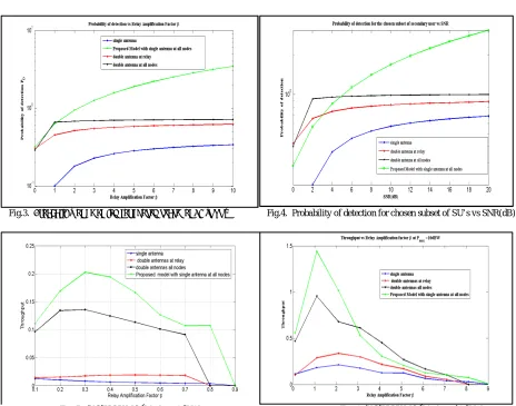
In the simulation, simulation parameters are set as follows: N = 100, Pd’ = 0.95, PF’ = 0.01, Pu = 0 dBW, and Pp = 0
dBW, α = 0.3 (means the (PU) is present for 30% of the time). The gains of the links between Gsr, Grd, and Gpr are
chosen to be −4 dB, and the gains of the links between Gps, Gsd, are chosen to be −10 dB. Fig.3. shows that the results
of probability of detection for chosen subset of SU versus relay amplification factor. From this figure, PD increases of
our proposed model when beta increase, which is compared with existing work[18]. Fig.4. Shows that the results of PD
versus different values of SNR(dB). From this figure, different values of SNR, PD increases of our proposed model as
Fig.3. Probability of detection for chosen subset of SU’s vs β Fig.4. Probability of detection for chosen subset of SU’s vs SNR(dB)
Fig. 5. Throughput vs β at Pmax=0dBW Fig. 6. Throughput vs β at Pmax=10dBW
V. CONCLUSION AND FUTURE WORK
In this paper, we studied the problem of designing the optimal sensing capabilities and power allocation strategy that maximizes secondary users throughput of cognitive radio network. The power allocation is the function of the received signal energy by the secondary user. Finally, the simulation results have shown that the Secondary users can achieve a significant capacity gain under the proposed model, compared with the conventional spectrum sharing model. In future our work is extend using different fading channels.
.
REFERENCES
1. E. Biglieri, A. J. Goldsmith, L. J. Greenstein, N. B. Mandayam, and H. V. Poor, “Principles of Cognitive Radio”. New York: Cambridge University press, 2012.
2. M. M. Buddhikot, “Understanding dynamic spectrum access: Models, taxonomy and challenges," Proc. IEEE DySPAN, pp. 649-663, April 2007.
3. FCC, “Spectrum Policy Task Force," ET Docket no. 02-135, Tech. Rep.,Nov 2002.
4. J. M. III and G. Q. Maguire, “Cognitive Radio: Making Software RadiosMore Personal," IEEE Personal Communications, vol. 6, no. 4, pp. 13-18, Aug. 1999.
6. T. Issariyakul, L. S. Pillutla, and V. Krishnamurthy, “Tuning Radio Resource in an Overlay Cognitive Radio Network for TCP: Greed Isn't Good," IEEE Commun Mag., vol. 47, no. 7, pp. 57-63, July 2009.
7. S. Haykin, D. J. Thomson, and J. H. Reed, “Spectrum Sensing for Cognitive Radio," Proc. IEEE, vol. 97, no. 5, pp. 849-877, May 2009. 8. B.C.Levy, “Principles of Signal Detection and Parameter Estimation”, New York: Springer, 2008.
9. T. Yucek and H. Arslan,“A Survey of Spectrum Sensing Algorithms for Cognitive Radio Applications," IEEE Comm. Surveys and Tutorial, vol. 11, no. 1, pp. 116-130, Mar 2009.
10. H. Urkowitz, “Energy detection of unknown deterministic signals," Proc. IEEE, vol. 55, no. 4, pp. 523-531, Apr 1967.
11. D. Cabric, S. Mishra, and R. Brodersen, “Implementation issues in Spectrum Sensing for Cognitive Radios," Proc. Asilomar Conf. on Signals, Systems and Computers, vol. 1, pp. 772-776, Nov 2004.
12. M. Ghozzi, F. Marx, M. Dohler, and J. Palicot, “Cyclostationarity-based test for detection of vacant frequency bands," Proc. IEEE Int. Conf. Cognitive Radio Oriented Wireless Networks and Commun. (Crown-com), June 2006.
13. H.Tang, “Some physical layer issues of wide-band cognitive radio systems," Proc. IEEE Int. Symposium on New Frontiers in Dynamic Spectrum Access Networks, pp. 151-159, Nov 2005.
14. I. F. Akyildiz, B. F. Lo, and R. Balakrishnan, “Cooperative Spectrum Sensing in Cognitive radio networks: A survey," Physical Communication, vol. 4, pp. 40-62, March 2011.
15. J. N. Laneman and G. W. Wornel, “Energy-Efficient Antenna Sharing And Relaying For Wireless Networks," Proc. IEEE WCNC, pp. 7-12, Nov 2000.
16. Raja and P. Viswanath, “Compress-And-Forward Scheme For A Relay Network: Approximate Optimality And Connection To Algebraic Flows," in Proc. of IEEE International Symposium on Information Theory (ISIT), pp. 1698-1702, Aug 2011.
17. Hyungjong Kim, Sungmook Lim, Daesik Hong, “Optimal Power Allocation and Outage Analysis for Cognitive Full Duplex Relay Systems”, Ieee Transactions On Wireless Communications, Volume:11 , Iss. 10, October 2012.
18. A. M. Benaya ,Mona Shokair , El-Sayed El-Rabaie , M. F. Elkordy “Optimal Power Allocation for Sensing-Based Spectrum Sharing in MIMO Cognitive Relay Networks”, Wireless Personal Communication, DOI 10.1007/s11277-015-2373-7.
19. Giorgio Taricco, “Optimization of Linear Cooperative Spectrum Sensing for Cognitive Radio Networks”, IEEE Journal Of Selected Topics In Signal Processing, Vol. 5, No. 1, February 2011.
BIOGRAPHY
Soniya S. Christani has received her Bachelor degree in Electronics and Communication Engineering from Gujarat Technological University, Ahmedabad, India. Currently she is pursuing M.E (Communication system engineering) from Gujarat Technological University. Her area of interest include wireless communication, networking.