Smart Farming Using Driverless Tractor
(Swarm Based)
Pintu Kumar1, Praveen S2, Aaditya Sinha3, Rahul Kumar Patil4, Savita C.H5
UG Students, Department of ECE, SAIT, Bengaluru, Karnataka, India1,2,3,4
Assistant Professor, Department of ECE, SAIT, Bengaluru, Karnataka, India5
ABSTRACT: Smart farming using driverless tractor (Swarm based) is a prototype designed to improve the efficiency of farming works and to do the farming works automatically. Today scarcity of man power became the main threat for agriculture sector. It reduces the dependency on man power by doing the works automatically and also enables the ladies and some disabled persons to do farming. Here GPS is used to locate the coordinates of farming field where the task has to be performed. Swarm technology (co-ordination between different devices) is used to perform specific task between Master(Tractor) and Slave(Trolley & Tools).
KEYWORDS: GPS&GSM, C2500 RF transcievers, IR sensor, ATmega 2560 & 328.
I. INTRODUCTION
Agriculture Sector of Indian Economy is one of the most significant part of India. Agriculture is the only means of living for almost two-thirds of the employed class in India. Indian Agriculture sector is more backward sector than other & ignored by my inventors. Result of this that there is no such machine or tool available which can reduce man power, increase productivity & improve quality of product. There is no intelligent & autonomous tool available for this sector which can take its own decision & help in reducing man power. The entire tool required man power even though if same task is being repeated this results the wastage of valuable time & man power both.
Keeping these things in mind we came up with this paper in which we tried our best to save valuable time & man power by designing autonomous & more intelligent tool for agriculture sector. Here we are designing a self-operated & intelligent Tractor and Trolley which takes input from farmer’s smart phone, process it, perform the task as per required & able to take its own decision in some circumstances.
A driverless tractor is a form of autonomous technology. It is considered driverless because it operates without the presence of a human inside the tractor itself. Like other unmanned ground vehicles, they are programmed to independently observe their position, decide speed and avoid obstacles such as people, animals or objects in the field, while performing their task The various driverless tractors are split into full autonomous technology.
The tractors use GPS and other wireless technologies to farm land without the need of a driver. They operate simply with the aid of a supervisor monitoring the progress at a control station or with a manned tractor in lead.
II. RELATED WORK
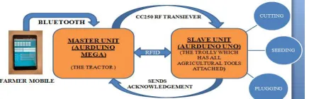
The prototype contains two units – master unit and slave unit.
Proposed system:
A. Master unit
Fig. 2: Master unit
The Main Important component of Master vehicle is HC-05 Bluetooth Module, GPS Module, cc2500 RF Trancievers Arduino Mega and motor driver unit.
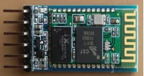
1) HC-05 Bluetooth Module:
Fig 3: Serial Port Bluetooth Module : HC-05 (IM120723010)
It is used to communicate between farmer’s smart phone and master unit. The farmer sends the commands to perform specific task to the master through this bluetooth device. The farmer controls the master by this bluetooth only.
2) GPS module:
The GPS is a space based navigation system that provides information on location anywhere on this earth. It makes use of 24 satellites that orbits the earth to get the location. The GPS receivers we use today are extremely accurate.It provides the exact location of the field where the task has to be performed.
3) RF module:
An RF module (radio frequency module) is a (usually) small electronic device used to transmit and/or receive radio signals between two devices. In an embedded system it is often desirable to communicate with another device wirelessly. This wireless communication may be accomplished through optical communication or through Radio Frequency communication.
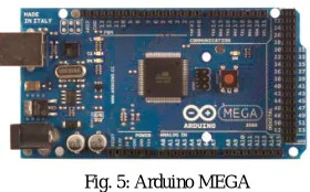
4) Arduino MEGA:
The Arduino Mega is a microcontroller board based on the ATmega2560. It has 54 digital input/output pins (of which 14 can be used as PWM outputs), 16 analog inputs, 4 UARTs (hardware serial ports), a 16 MHz crystal oscillator, a USB connection, a power jack, an ICSP header, and a reset button.
Fig. 5: Arduino MEGA
It contains everything needed to support the microcontroller; simply connect it to a computer with a USB cable or power it with a AC-to-DC adapter or battery to get started. The Mega is compatible with most shields designed for the Arduino Duemilanove or Diecimila.
5) Motor Driver Unit: 5.1: L293 motor driver:
Fig. 6:L293 motor driver
L293D is a typical Motor driver or Motor Driver IC which allows DC motor to drive on either direction. L293D is a 16-pin IC which can control a set of two DC motors simultaneously in any direction. It means that you can control two DC motor with a single L293D IC. Dual H-bridge Motor Driver integrated circuit(IC).
5.2: L298 motor driver:
Fig .7: L298 motor driver
L298N is a high voltage, high current motor driver chip, with the highest working voltage of 46V, continuous operating current of 2A, and instantaneous peak current up to 3A. The chip contains two "H bridges" which are high-voltage and high current full-bridge drivers that can directly drive two DC motors. The L298N H-bridge IC that can allows you to control the speed and direction of two DC motors, or control one bipolar stepper motor with ease. The
L298N
H-bridge module
can be used with motors that have a voltage of between 5 and 35V DC. With the module used in this tutorial, there is also an onboard 5V regulator, so if your supply voltage is up to 12V you can also source 5V from the board.B:Slave unit:
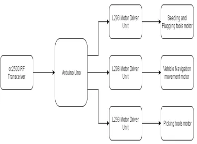
Fig 8: Block diagram of slave unit
1) Arduino UNO:
Fig. 9 Arduino UNO
This is the new Arduino Uno R3. In addition to all the features of the previous board, the Uno now uses an ATmega16U2 instead of the 8U2 found on the Uno (or the FTDI found on previous generations). This allows for faster transfer rates and more memory. No drivers needed for Linux or Mac (inf file for Windows is needed and included in the Arduino IDE), and the ability to have the Uno show up as a keyboard, mouse, joystick, etc.
2) IR sensor:
Infrared technology addresses a wide variety of wireless applications. The main areas are sensing and remote controls. Infrared technology addresses a wide variety of wireless applications. The main areas are sensing and remote controls. It is used to provide security from intruders in the field.
Fig. 10: IR sensor
III.METHODOLOGY
Master vehicle: Farmers send command through smartphone using app AurduDroid to Master vehicle using Bluetooth. Master vehicle has HC – 05 Bluetooth Module which receive the command and send it to Arduino Mega board for further processing. Arduino process the command and perform the operation accordingly.
The user can operate Master vehicle in 4 different modes.
MODE 1: Master Navigation control
MODE 2: Get GPS Location
In this Mode Farmer can send command to master vehicle to get the current GPS Location of Master Vehicle.
MODE 3: Slave Control
In This Mode Farmer / user can assign task to master and master will take help of slave to complete that task. We have implemented cutting task (on master and slave both), Plugging task (slave only), and Seeding task (slave only). So farmer can select any task to perform. If cutting task is selected then master and slave both will work together to complete the task and if seeding or plugging task is selected then master will instruct slave to perform task. Between master and slave handshaking will happen i.e. master will send any command and slave will send ACK for that command.
MODE 4: Master Cutting task
In this Mode farmer will send cutting task to Master. Since master has cutting tools so it will perform cutting operation. In this mode master will not ask any help of slave.
The control flow is as follows -
1) Master vehicle will receive commands from user through HC-05 Bluetooth Module. 2) This received command send to Arduino Mega for further processing.
3) If user has selected mode 1 then based on command Arduino will send control signal to L298 motor driver unit to control vehicle motor for vehicle movement and directions
4) If user has selected mode 2 then Arduino will start receiving GPS data and will extract latitude and longitude out of it to display current location of master vehicle and display it on 2x16 LCD.
5) If user has selected mode 4 then Arduino will send command to L293 motor driver unit to control operation of cutting tool attached to master vehicle. Simultaneously master vehicle will navigate to a predefined path (i.e. the movement for path navigation is predefined)
6) Master will continuously monitor for any ACK from slave (sent through cc2500) and any command from user (sent through Bluetooth).
Slave vehicle:
1) Slave vehicle operate as per master vehicle instruction.
2) When user operate Master vehicle in swarm mode i.e. Mode 3 then master will send instruction to slave through cc2500 RF transceiver to execute particular task.
3) Slave vehicle can execute 3 different task - cutting task, plugging task and seeding task.
4) In cutting task master vehicle will perform cutting operation and slave vehicle will do picking operation. So master vehicle will cut the crops and slave vehicle will pick the crops.
5) In plugging and seeding task master vehicle will not perform any task it will only send instruction to slave vehicle to execute particular tasks.
Algorithm for master & slave operation : The control flow is as follows:
1) Slave vehicle will receive command from master vehicle through cc2500 RF Transceiver. 2) All the received commands sends to Arduino uno for decision making and further processing. 3) Based on the task Arduino will instruct motor driver unit to operate.
4) For cutting task slave has gripper which work as a picking tool so when master will cut the crop slave will pick up it.
5) For cutting and seeding task master will send vehicle movement instruction also to slave so slave will navigate on a predefined path decided by master.
6) For plugging task only plugging tool is operated no vehicle movement is involved.
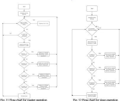
Fig .11 Flow chart for master operation Fig. 12 Flow chart for slave operation
IV. RESULTS
All the four modes are implemented using this prototype and the results are positive for all the modes. The assigned tasks such as cutting, seeding, plugging are successfully carried out and the machine to machine communication (Swarm based) has been achieved during the operation.
Fig. 13 Prototype proposed system
accurately up and down the rows, even in the presence of hazards such as irrigation ditches. We are sure this is going to great help to our farmer because it is a affordable and low cost with user friendly to access also.
REFERENCES
[1] W.Burgard, M.Moors, C.Stachniss and F. Schneider, “Coordinated Multi-Robot exploration” in Robotics, 2005.
[2] M. A. Labrador. Communication-assisted topology control of semiautonomous robots. Proceedings of 31st IEEE Conference in Local Computer Networks,2006,563-564.
[3] V. Gazi and K. M. Passino, “Stability analysis of social foragingswarms,” in IEEE Trans. on Systems, Man, and Cybernetics, vol. 34,no. 1, 2004
[4] Zhu Hong-guo, Zheng Chang-wen, Hu Xiao-hui, Li Xiang. PathPlanner for Unmanned Aerial Vehicles Based on Modified PSO Algorithm. In Proc. the IEEE International Conference on Information and Automation, Zhangjiajie, China, 2008, pp. 541–544..